Figure 2.6 ESI apparatus for offline analysis with microscope imaging.

MODELING AND CHARACTERIZATION OF MICROFABRICATED EMITTERS: IN PURSUIT OF IMPROVED ESI-MS PERFORMANCE

미세 가공 방사체의 모델링 및 특성화 : 개선된 ESI-MS 성능 추구

by XINYUN WU

A thesis submitted to the Department of Chemistry in conformity with the requirements for the degree of Master of Science Queen’s University Kingston, Ontario, Canada December, 2011 Copyright © Xinyun Wu, 2011

Abstract

ESI (Electrospray ionization)는 특히 탁월한 감도, 견고성 및 단순성으로 대형 생체 분자를 분석하는 데있어 질량 분석 (MS)에 매우 귀중한 기술이었습니다. ESI 기술 개발에 많은 노력을 기울였습니다. 그 형태와 기하학적 구조가 전기 분무 성능과 추가 MS 감지에 중추적 인 것으로 입증 되었기 때문입니다.

막힘 및 낮은 처리량을 포함하여 전통적인 단일 홀 이미터의 본질적인 문제는 기술의 적용 가능성을 제한합니다. 이 문제를 해결하기 위해 현재 프로젝트는 향상된 ESI-MS 분석을위한 다중 전자 분무(MES) 방출기를 개발하는데 초점을 맞추고 있습니다.

이 논문에서는 스프레이 전류 측정을 위한 전기 분무와 오프라인 전기 분무 실험을 위한 전산 유체 역학 (CFD) 시뮬레이션의 공동 작업이 수행되었습니다. 전기 분무 성능에 대한 다양한 이미터 설계의 영향을 테스트하기 위해 수치 시뮬레이션이 사용되었으며 실험실 결과는 가이드 및 검증으로 사용되었습니다.

CFD 코드는 Taylor-Melcher 누설 유전체 모델(LDM)을 기반으로 하며 과도 전기 분무 공정이 성공적으로 시뮬레이션되었습니다.

이 방법은 750 μm 내경 (i.d.) 이미 터를 통해 먼저 검증되었으며 20 μm i.d.에 추가로 적용되었습니다. 모델. 전기 분무 공정의 여러 단계가 시각적으로 시연되었으며 다양한 적용 전기장 및 유속에서 분무 전류의 변화에 ​​대한 정량적 조사는 이전 시뮬레이션 및 측정과 잘 일치합니다.

단일 조리개 프로토 타입을 기반으로 2 홀 및 3 홀 이미터로 MES 시뮬레이션을 수행했습니다. 시뮬레이션 예측은 실험 결과와 유사하게 비교되었습니다. 이 작업의 증거는 CFD 시뮬레이션이 MES의 이미 터 설계를 테스트하는 효과적인 수치 도구로 사용될 수 있음을 입증했습니다.

이 작업에서 달성 된 마이크로 스케일 에미 터 전기 분무의 성공적인 시뮬레이션에 대한 벤치마킹 결과는 현재까지 발표 된 전기 분무에 대한 동적 시뮬레이션의 가장 작은 규모로 여겨집니다.

Co-Authorship

공동 저자: 이 논문에 대한 모든 연구는 Natalie M. Cann 박사와 Richard D. Oleschuk 박사의 지도하에 완료되었습니다. 다중 전자 분무에 관한 4 장에서 제시된 연구 작업의 일부는 Ramin Wright가 공동 저술했으며, 이 작업은 press에서 다음 논문에서 인용되었습니다.

ibson,G.T.T.; Wright, R.D.; Oleschuk, R.D. Multiple electrosprays generated from a single poly carbonate microstructured fibre. Journal of Mass Spectrometry, 2011, in press.

Chapter 1 Introduction

소프트 이온화 방법으로 ESI (electrospray ionization)의 도입은 질량 분석법 (MS)의 적용 가능성에 혁명을 일으켰습니다. 이 기술의 부드러운 특징은 상대적으로 높은 전하를 가진 이온을 생성하는 고유한 이점으로 인해 액상에서 직접 펩티드 및 단백질과 같은 큰 생체 분자를 분석 할 수 있게했습니다 [1].

지난 10 년 동안 ESI-MS는 놀라운 성장을 보였으며 현재는 단백질 체학, 대사 체학, 글리코 믹스, 합성 화학자를 위한 식별 도구 등 다양한 생화학 분야에서 광범위하게 채택되고 있습니다 [2-3].

ESI-MS는 겔 전기 영동과 같은 생물학적 분자에 대한 기존의 질량 측정 기술보다 훨씬 빠르고 민감하며 정확합니다. 또한, 액체상에서 직접 분석 할 수 있는 큰 비 휘발성 분자의 능력은 고성능 액체 크로마토 그래피 (HPLC) 및 모세관 전기 영동 (CE)과 같은 업스트림 분리 기술과의 결합을 가능하게합니다 [4].

일반적인 ESI 공정은 일반적으로 액적 형성, 액적 수축 및 기상 이온의 최종 형성을 포함합니다. 일렉트로 스프레이의 성능에 영향을 미치는 많은 요소 중에서 스프레이를 위한 이미터의 구조 (즉, 기하학, 모양 등)가 중요한 요소입니다.

전통적인 전기 분무 이미터는 일반적으로 풀링 또는 에칭 기술로 제작 된 단일 채널 테이퍼 형 또는 비 테이퍼 형입니다. 그러나 이러한 이미터는 종종 막힘, 부적절한 처리량 등과 같은 문제로 어려움을 겪습니다. [5]

향상된 감도 및 샘플 활용을 위해 다중 스프레이를 생성하는 새로운 이미터 설계 개발로 분명한 발전이 있었습니다. 새로운 ESI 이미터 설계에 대한 연구는 실험적으로나 이론적으로 큰 관심을 불러 일으켰습니다 [3]. 그러나 ESI의 복잡한 물리적 과정은 팁 형상 외에도 많은 다른 변수에 의존하기 때문에 연구간 직접 비교의 어려움은 장애물이 됩니다.

또한 새로운 나노 이미터 제조 및 테스트 비용이 상당히 높을 수 있습니다. 이 논문은 CFD 시뮬레이션 도구를 활용하여 가상 랩을 설정함으로써 이러한 문제를 해결합니다. 다른 매개 변수로 인해 상호 연결된 변경 없이 다양한 이미터 설계를 비교할 수 있도록 이상적으로 균일한 물리적 조건을 제공합니다.

맞춤 제작된 프로토 타입의 실험 측정 값도 수집되어 더 나은 계산 체계를 형성하는 데 도움이 되는 지침과 검증을 모두 제공합니다. 특히 이 분야의 주요 미래 플랫폼으로 여겨지는 다중 노즐 이미 터 설계에 중점을 둘 것입니다.

전기 분무 거동에 영향을 미치는 요인에 대한 추가 기본 연구는 다양한 기하학적 및 작동 매개 변수와 관련하여 수행됩니다. 이는 보다 효율적이고 견고한 이미터의 개발을 가능하게 할 뿐만 아니라 더 넓은 영역에서 ESI의 적용을 향상시킬 수 있습니다.

Figure 1.1Schematic setup for ESI-MS technique
Figure 1.2 Schematic of major processes occurring in electrospray [5].
Figure 1.3 Illustration of detailed geometric parameters of a spraying Taylor cone wherera is the radius of curvature of the best fitting circle at the tip of the cone; re is the radius of the emission region for droplets at the tip of a Taylor cone;is the liquid cone angle.
Figure 1.4 (A)Externally tapered emitter  (B) Optical image of a clogged tapered emitter with normal use [46].
Figure 1.4 (A)Externally tapered emitter (B) Optical image of a clogged tapered emitter with normal use [46].
Figure 1.5 (A)Three by three configuration of an emitter array made with polycarbonate using laser ablation; (B) Photomicrograph of nine stable electrosprays generated from the nine-emitter array [52]
Figure 1.6 SEM images of the distal ends of four multichannel nanoelectrospray emitters and a tapered emitter: (A) 30 orifice emitter; (B) 54 orifice emitter; (C) 84 orifice emitter; (D) 168 orifice emitter; Scale bars in A, B, and C represent 50 μm, and 100 μm in D[54]
Figure 1.7 Photomicrographs of electrospray from of a 168-hole MCN emitter at different flow rates. (A) A traditional integrated Taylor cone observed from offline electrospray of water with 0.1% formic acid at 300 nL/min; (B) A mist of coalesced Taylor cones observed from offline electrospray at 25 nL/min[54]
Figure 1.8 Circular arrays of etched emitters for better electric field homogeneity [53].
Figure 2.6 ESI apparatus for offline analysis with microscope imaging.
Figure 3.9 Typical panel for displaying instant simulation result during simulation process.
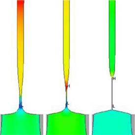
Figure 5.3 Generation of a Taylor cone-jet mode (simulation) plotted with iso-potential lines at times    (Top to bottom panels correspond to 0.002 s, 0.012 s, 0.018 s, 0.08 s respectively).
Figure 5.3 Generation of a Taylor cone-jet mode (simulation) plotted with iso-potential lines at times (Top to bottom panels correspond to 0.002 s, 0.012 s, 0.018 s, 0.08 s respectively).
Figure 5.8 (A) Taylor cone-jet profiles with different contact angle of 30 degrees and 20 degrees (B) under the same physical conditions of 6 kV and 0.04 m/s. (C) Cone-jet profile generated from a tapered tip with a 20 degree contact angle at 6 kV and 0.04 m/s (as a comparison with (B)).

Omit below: Please refer to the original text for the full content.

Bibliography

1. Mclafferty, F.W., Tandem Fourier-Transform Mass-Spectrometry of Large Molecules.Abstracts of Papers of the American Chemical Society, 1986. 192: p. 21-Anyl. 2. Griffiths, W.J. and Y.Q. Wang, Mass spectrometry: from proteomics to metabolomics and lipidomics. Chemical Society Reviews, 2009. 38(7): p. 1882-1896. 3. Gibson, G.T.T., S.M. Mugo, and R.D. Oleschuk, Nanoelectrospray Emitters: Trends and Perspective. Mass Spectrometry Reviews, 2009. 28(6): p. 918-936. 4. Cech, N.B. and C.G. Enke, Practical implications of some recent studies in electrospray ionization fundamentals. Mass Spectrometry Reviews, 2001. 20(6): p. 362-387. 5. Su, S., Development and Application of Non-tapered Electrospray Emitters for Nano-ESI Mass Spectrometry, in Chemistry. 2008, Queen’s University: Kingston. p. 185. 6. Zeleny, J., The electrical discharge from liquid points, and a hydrostatic method of measuring the electric intensity at their surfaces. Physical Review, 1914. 3(2): p. 69-91. 7. Dole, M., L.L. Mack, and R.L. Hines, Molecular Beams of Macroions. Journal of Chemical Physics, 1968. 49(5): p. 2240-&. 8. Yamashita, M. and J.B. Fenn, Negative-Ion Production with the Electrospray Ion-Source.Journal of Physical Chemistry, 1984. 88(20): p. 4671-4675. 9. Kebarle, P. and U.H. Verkerk, Electrospray: From Ions in Solution to Ions in the Gas Phase, What We Know Now. Mass Spectrometry Reviews, 2009. 28(6): p. 898-917. 10. Taylor, G., Disintegration of Water Drops in Electric Field. Proceedings of the Royal Society of London Series a-Mathematical and Physical Sciences, 1964. 280(138): p. 383. 11. Cole, R.B., Some tenets pertaining to electrospray ionization mass spectrometry. Journal of Mass Spectrometry, 2000. 35(7): p. 763-772. 12. Rayleigh, L., On the equilibrium of liquid conducting masses charged with electricity.Philos. Mag., 1882. 14: p. 184-186. 13. Mack, L.L., et al., Molecular Beams of Macroions .2. Journal of Chemical Physics, 1970. 52(10): p. 4977-&. 14. Gamero-Castano, M. and J.F. de la Mora, Kinetics of small ion evaporation from the charge and mass distribution of multiply charged clusters in electrosprays. Journal of Mass Spectrometry, 2000. 35(7): p. 790-803. 15. Gamero-Castano, M. and J.F. de la Mora, Modulations in the abundance of salt clusters in electrosprays. Analytical Chemistry, 2000. 72(7): p. 1426-1429. 16. Loscertales, I.G. and J.F. Delamora, Experiments on the Kinetics of Field Evaporation of Small Ions from Droplets. Journal of Chemical Physics, 1995. 103(12): p. 5041-5060. 17. Rohner, T.C., N. Lion, and H.H. Girault, Electrochemical and theoretical aspects of electrospray ionisation. Physical Chemistry Chemical Physics, 2004. 6(12): p. 3056-3068.

18. Iribarne, J.V. and B.A. Thomson, Evaporation of Small Ions from Charged Droplets.Journal of Chemical Physics, 1976. 64(6): p. 2287-2294. 19. Meng, C.K. and J.B. Fenn, Formation of Charged Clusters during Electrospray Ionization of Organic Solute Species. Organic Mass Spectrometry, 1991. 26(6): p. 542-549. 20. Nohmi, T. and J.B. Fenn, Electrospray Mass-Spectrometry of Poly(Ethylene Glycols) with Molecular-Weights up to 5 Million. Journal of the American Chemical Society, 1992. 114(9): p. 3241-3246. 21. de la Mora, J.F., Electrospray ionization of large multiply charged species proceeds via Dole’s charged residue mechanism. Analytica Chimica Acta, 2000. 406(1): p. 93-104. 22. Iavarone, A.T., J.C. Jurchen, and E.R. Williams, Supercharged protein and peptide lone formed by electrospray ionization. Analytical Chemistry, 2001. 73(7): p. 1455-1460. 23. Hogan, C.J., et al., Charge carrier field emission determines the number of charges on native state proteins in electrospray ionization. Journal of the American Chemical Society, 2008. 130(22): p. 6926-+. 24. Nguyen, S. and J.B. Fenn, Gas-phase ions of solute species from charged droplets of solutions. Proceedings of the National Academy of Sciences of the United States of America, 2007. 104(4): p. 1111-1117. 25. Luedtke, W.D., et al., Nanojets, electrospray, and ion field evaporation: Molecular dynamics simulations and laboratory experiments. Journal of Physical Chemistry A, 2008. 112(40): p. 9628-9649. 26. Enke, C.G., A predictive model for matrix and analyte effects in electrospray ionization of singly-charged ionic analytes. Analytical Chemistry, 1997. 69(23): p. 4885-4893. 27. Maze, J.T., T.C. Jones, and M.F. Jarrold, Negative droplets from positive electrospray.Journal of Physical Chemistry A, 2006. 110(46): p. 12607-12612. 28. Kebarle, P. and M. Peschke, On the mechanisms by which the charged droplets produced by electrospray lead to gas phase ions. Analytica Chimica Acta, 2000. 406(1): p. 11-35. 29. Loeb, L.B., A.F. Kip, and G.G. Hudson, Pulses in negative point-to-plane corona.Physical Review, 1941. 60(10): p. 714-722. 30. Cole, R.B., Electrospray ionization mass spectrometry : fundamentals, instrumentation, and applications. 1997, New York: Wiley. xix, 577 p. 31. Smith, D.P.H., The Electrohydrodynamic Atomization of Liquids. Ieee Transactions on Industry Applications, 1986. 22(3): p. 527-535. 32. Taylor, G.I. and A.D. Mcewan, Stability of a Horizontal Fluid Interface in a Vertical Electric Field. Journal of Fluid Mechanics, 1965. 22: p. 1-&. 33. Ikonomou, M.G., A.T. Blades, and P. Kebarle, Electrospray Mass-Spectrometry of Methanol and Water Solutions Suppression of Electric-Discharge with Sf6 Gas. Journal of the American Society for Mass Spectrometry, 1991. 2(6): p. 497-505.

34. Wampler, F.M., A.T. Blades, and P. Kebarle, Negative-Ion Electrospray Mass-Spectrometry of Nucleotides – Ionization from Water Solution with Sf6 Discharge Suppression. Journal of the American Society for Mass Spectrometry, 1993. 4(4): p. 289-295. 35. Marginean, I., P. Nemes, and A. Vertes, Order-chaos-order transitions in electrosprays: The electrified dripping faucet. Physical Review Letters, 2006. 97(6): p. -. 36. Marginean, I., P. Nemes, and A. Vertes, Astable regime in electrosprays. Physical Review E, 2007. 76(2): p. -. 37. Nemes, P., I. Marginean, and A. Vertes, Spraying mode effect on droplet formation and ion chemistry in electrosprays. Analytical Chemistry, 2007. 79(8): p. 3105-3116. 38. Marginean, I., et al., Electrospray characteristic curves: In pursuit of improved performance in the nanoflow regime. Analytical Chemistry, 2007. 79(21): p. 8030-8036. 39. Page, J.S., et al., Subambient pressure ionization with nanoelectrospray source and interface for improved sensitivity in mass spectrometry. Analytical Chemistry, 2008. 80(5): p. 1800-1805. 40. Delamora, J.F. and I.G. Loscertales, The Current Emitted by Highly Conducting Taylor Cones. Journal of Fluid Mechanics, 1994. 260: p. 155-184. 41. Ganan-Calvo, A.M., On the general scaling theory for electrospraying. Journal of Fluid Mechanics, 2004. 507: p. 203-212. 42. Smith, D.R., G. Sagerman, and T.D. Wood, Design and development of an interchangeable nanomicroelectrospray source for a quadrupole mass spectrometer.Review of Scientific Instruments, 2003. 74(10): p. 4474-4477. 43. Barnidge, D.R., S. Nilsson, and K.E. Markides, A design for low-flow sheathless electrospray emitters. Analytical Chemistry, 1999. 71(19): p. 4115-4118. 44. Guzzetta, A.W., R.A. Thakur, and I.C. Mylchreest, A robust micro-electrospray ionization technique for high-throughput liquid chromatography/mass spectrometry proteomics using a sanded metal needle as an emitter. Rapid Communications in Mass Spectrometry, 2002. 16(21): p. 2067-2072. 45. Wilm, M. and M. Mann, Analytical properties of the nanoelectrospray ion source.Analytical Chemistry, 1996. 68(1): p. 1-8. 46. Covey, T.R. and D. Pinto, Practical Spectroscopy. Vol. 32. 2002. 47. Kelly, R.T., et al., Nanoelectrospray emitter arrays providing interemitter electric field uniformity. Analytical Chemistry, 2008. 80(14): p. 5660-5665. 48. Choi, Y.S. and T.D. Wood, Polyaniline-coated nanoelectrospray emitters treated with hydrophobic polymers at the tip. Rapid Communications in Mass Spectrometry, 2007. 21(13): p. 2101-2108. 49. Tojo, H., Properties of an electrospray emitter coated with material of low surface energy. Journal of Chromatography A, 2004. 1056(1-2): p. 223-228.

50. Liu, J., et al., Electrospray ionization with a pointed carbon fiber emitter. Analytical Chemistry, 2004. 76(13): p. 3599-3606. 51. Sen, A.K., et al., Modeling and characterization of a carbon fiber emitter for electrospray ionization. Journal of Micromechanics and Microengineering, 2006. 16(3): p. 620-630. 52. Tang, K.Q., et al., Generation of multiple electrosprays using microfabricated emitter arrays for improved mass spectrometric sensitivity. Analytical Chemistry, 2001. 73(8): p. 1658-1663. 53. Deng, W. and A. Gomez, Influence of space charge on the scale-up of multiplexed electrosprays. Journal of Aerosol Science, 2007. 38(10): p. 1062-1078. 54. Su, S.Q., et al., Microstructured Photonic Fibers as Multichannel Electrospray Emitters.Analytical Chemistry, 2009. 81(17): p. 7281-7287. 55. Sen, A.K., J. Darabi, and D.R. Knapp, Simulation and parametric study of a novel multi-spray emitter for ESI-MS applications. Microfluidics and Nanofluidics, 2007. 3(3): p. 283-298. 56. Hayati, I., A. Bailey, and T.F. Tadros, Investigations into the Mechanism of Electrohydrodynamic Spraying of Liquids .2. Mechanism of Stable Jet Formation and Electrical Forces Acting on a Liquid Cone. Journal of Colloid and Interface Science, 1987. 117(1): p. 222-230. 57. Glonti, G.A., On the Theory of the Stability of Liquid Jets in an Electric Field. Soviet Physics Jetp-Ussr, 1958. 7(5): p. 917-918. 58. Nayyar, N.K. and G.S. Murty, The Stability of a Dielectric Liquid Jet in the Presence of a Longitudinal Electric Field. Proceedings of the Physical Society of London, 1960. 75(483): p. 369-373. 59. Allan, R.S. and S.G. Mason, Particle Behaviour in Shear and Electric Fields .1. Deformation and Burst of Fluid Drops. Proceedings of the Royal Society of London Series a-Mathematical and Physical Sciences, 1962. 267(1328): p. 45-&. 60. Melcher, J.R. and G.I. Taylor, Electrohydrodynamics – a Review of Role of Interfacial Shear Stresses. Annual Review of Fluid Mechanics, 1969. 1: p. 111-&. 61. Saville, D.A., Electrohydrodynamics: The Taylor-Melcher leaky dielectric model. Annual Review of Fluid Mechanics, 1997. 29: p. 27-64. 62. Carretero Benignos, J.A. and Massachusetts Institute of Technology. Dept. of Mechanical Engineering., Numerical simulation of a single emitter colloid thruster in pure droplet cone-jet mode. 2005. p. 117 leaves. 63. Hartman, R.P.A., et al., The evolution of electrohydrodynamic sprays produced in the cone-jet mode, a physical model. Journal of Electrostatics, 1999. 47(3): p. 143-170. 64. Hartman, R.P.A., et al., Electrohydrodynamic atomization in the cone-jet mode physical modeling of the liquid cone and jet. Journal of Aerosol Science, 1999. 30(7): p. 823-849.

65. Yoon, S.S., et al., Modeling multi-jet mode electrostatic atomization using boundary element methods. Journal of Electrostatics, 2001. 50(2): p. 91-108. 66. Zeng, J., D. Sobek, and T. Korsmeyer, Electro-hydrodynamic modeling of electrospray ionization: Cad for a mu fluidic device – Mass spectrometer interface. Boston Transducers’03: Digest of Technical Papers, Vols 1 and 2, 2003: p. 1275-1278, 1938. 67. Lastow, O. and W. Balachandran, Numerical simulation of electrohydrodynamic (EHD) atomization. Journal of Electrostatics, 2006. 64(12): p. 850-859. 68. http://www.flow3d.com. 69. Valaskovic, G.A., et al., Attomole-Sensitivity Electrospray Source for Large-Molecule Mass-Spectrometry. Analytical Chemistry, 1995. 67(20): p. 3802-3805. 70. Kriger, M.S., K.D. Cook, and R.S. Ramsey, Durable Gold-Coated Fused-Silica Capillaries for Use in Electrospray Mass-Spectrometry. Analytical Chemistry, 1995. 67(2): p. 385-389. 71. Fang, L.L., et al., Online Time-of-Flight Mass-Spectrometric Analysis of Peptides Separated by Capillary Electrophoresis. Analytical Chemistry, 1994. 66(21): p. 3696-3701. 72. Cao, P. and M. Moini, A novel sheathless interface for capillary electrophoresis/electrospray ionization mass spectrometry using an in-capillary electrode. Journal of the American Society for Mass Spectrometry, 1997. 8(5): p. 561-564. 73. Fong, K.W.Y. and T.W.D. Chan, A novel nonmetallized tip for electrospray mass spectrometry at nanoliter flow rate. Journal of the American Society for Mass Spectrometry, 1999. 10(1): p. 72-75. 74. Emmett, M.R. and R.M. Caprioli, Micro-Electrospray Mass-Spectrometry – Ultra-High-Sensitivity Analysis of Peptides and Proteins. Journal of the American Society for Mass Spectrometry, 1994. 5(7): p. 605-613. 75. Gatlin, C.L., et al., Protein identification at the low femtomole level from silver-stained gels using a new fritless electrospray interface for liquid chromatography microspray and nanospray mass spectrometry. Analytical Biochemistry, 1998. 263(1): p. 93-101. 76. Aturki, Z., et al., On-line CE-MS using pressurized liquid junction nanoflow electrospray interface and surface-coated capillaries. Electrophoresis, 2006. 27(23): p. 4666-4673. 77. Edwards, J.L., et al., Negative mode sheathless capillary electrophoresis electrospray ionization-mass spectrometry for metabolite analysis of prokaryotes. Journal of Chromatography A, 2006. 1106(1-2): p. 80-88. 78. http://www.kiriama.com/kiriama%20single-mode%20polymer%20fibers_009.htm. 79. Wilm, M.S. and M. Mann, Electrospray and Taylor-Cone Theory, Doles Beam of Macromolecules at Last. International Journal of Mass Spectrometry, 1994. 136(2-3): p. 167-180.

80. Hirt, C.W. and B.D. Nichols, Volume of Fluid (Vof) Method for the Dynamics of Free Boundaries. Journal of Computational Physics, 1981. 39(1): p. 201-225. 81. Melcher, J.R., Continuum electromechanics. 1981, Cambridge, Mass.: MIT Press. 1 v. (various pagings). 82. http://www.flow3d.com/cfd-101/cfd-101-FAVOR.html. 83. http://www.flow3d.com/cfd-101/cfd-101-FAVOR-no-loss.html. 84. Savage, B.M. and M.C. Johnson, Flow over ogee spillway: Physical and numerical model case study. Journal of Hydraulic Engineering-Asce, 2001. 127(8): p. 640-649. 85. http://www.flow3d.com/cfd-101/cfd-101-free-surface-fluid-flow.html. 86. Graham T. T. Gibson, R.D.W.a.R.D.O., Multiple electrosprays generated from a single poly carbonate microstructured fibre. Mass Spectrometry, 2011. 87. Smith, R.D., et al., Analytical characterization of the electrospray ion source in the nanoflow regime. Analytical Chemistry, 2008. 80(17): p. 6573-6579. 88. Hirt, C.W., Electro-hydrodynamics of semi-conductive fluids: with application to electro-spraying. Flow Science Technical Note, 2004. 70(FSI–04–TN70): p. 1-7. 89. de la Mora, J.F., The fluid dynamics of Taylor cones. Annual Review of Fluid Mechanics, 2007. 39: p. 217-243. 90. Cloupeau, M. and B. Prunetfoch, Electrostatic Spraying of Liquids in Cone-Jet Mode.Journal of Electrostatics, 1989. 22(2): p. 135-159. 91. Hayati, I., A.I. Bailey, and T.F. Tadros, Investigations into the Mechanisms of Electrohydrodynamic Spraying of Liquids .1. Effect of Electric-Field and the Environment on Pendant Drops and Factors Affecting the Formation of Stable Jets and Atomization. Journal of Colloid and Interface Science, 1987. 117(1): p. 205-221. 92. FLOW-3D User Manual, Ver. 9.4. 93. Sen, A.K., J. Darabi, and D.R. Knapp, Analysis of Droplet Generation in Electrospray Using a Carbon Fiber Based Microfluidic Emitter. Journal of Fluids Engineering-Transactions of the Asme, 2011. 133(7).

Figure 20. Top: image of electrospray, bottom: cone-jet profile using the CF emitter. Distance between the carbon fiber tip and the counter electrode is 4.0 mm, potential difference is 3500 V, flow rate is 300 nL min−1 .

Modeling and characterization of a carbon fiber emitter for electrospray ionization

A K Sen1, J Darabi1, D R Knapp2 and J Liu2
1 MEMS and Microsystems Laboratory, Department of Mechanical Engineering,
University of South Carolina, 300 Main Street, Columbia, SC 29208, USA
2 Department of Pharmacology, Medical University of South Carolina, 173 Ashley Avenue,
Charleston, SC 29425, USA
E-mail: darabi@engr.sc.edu

뾰족한 탄소 섬유(CF)를 사용하는 새로운 마이크로 스케일 이미터는 질량 분석 (MS) 분석에서 전기 분무에 사용할 수 있습니다. 탄소 섬유는 360 µm OD 및 75 µm ID의 용융 실리카 모세관과 동축에 위치하며 날카로운 팁은 튜브 말단에서 30 µm 연장됩니다.

Abstract

전기 분무 이온화 (ESI) 프로세스는 전기 유체 역학을 해결하기 위한 Taylor–Melcher 누설 유전체 유체 모델 및 액체-가스 인터페이스 추적을 위한 유체 부피 (VOF) 접근 방식을 기반으로 하는 전산 유체 역학 (CFD) 코드를 사용하여 시뮬레이션 됩니다. CFD 코드는 먼저 기존 지오메트리에 대해 검증한 다음 CF 이미터 기반 ESI 모델을 시뮬레이션하는데 사용됩니다.

시뮬레이션된 전류 흐름 및 전류 전압 결과는 CF 이미터의 실험 결과와 잘 일치합니다. 이미터 형상, 전위차, 유속 및 액체의 물리적 특성이 CF 이미터의 전기 분무 거동에 미치는 영향을 철저히 조사합니다.

스프레이 전류와 제트 직경은 액체의 유속, 전위차 및 물리적 특성과 상관 관계가 있으며 상관 결과는 문헌에 보고된 결과와 정량적으로 비교됩니다. (이 기사의 일부 그림은 전자 버전에서만 색상입니다)

Introduction

1980 년대 후반부터 매트릭스 보조 레이저 탈착 이온화 (MALDI)와 전기 분무 이온화 (ESI)의 두 가지 이온화 기술을 구현하여 감도, 속도 및 구조 정보 수준 측면에서 MS 분석이 엄청나게 성장했습니다. 1980 년대 초까지 전자 충격 (EI) 또는 화학 이온화 (CI) 방법은 가스 크로마토 그래피에 적합한 작은 생체 분자를 이온화 하는 데 사용되었습니다.

그러나 크고 열에 민감한 비 휘발성 샘플은 적절한 사전 처리 없이 EI 또는 CI-MS 기술로 분석 할 수 없습니다 [1]. ESI 기술을 사용하면 액체상에서 직접 이러한 큰 분자를 분석 할 수 있습니다 [2]. Zeleny [3, 4]는 출구에 높은 전위를 적용하여 모세관에서 액체 용액을 분사 할 수 있음을 보여주었습니다.

Dole [5, 6] 및 Fenn [7]의 선구적인 연구는 ESI를 고분자 및 생체 분자와 같은 대형 화합물의 이온화 방법으로 표시했습니다. 이에 이어이 기술에 의한 기상 이온 발생에 관련된 과정과 메커니즘이 널리 조사되고 있습니다.

ESI 방법에서 기체 이온화 된 분자는 강한 전계가 있는 상태에서 미세한 물방울을 생성하여 액체 용액에서 생성됩니다. ESI 프로세스의 이러한 능력은 단백질 및 기타 생체 분자 연구에 자연적으로 적용됨을 발견했습니다. ESI 방법과 관련된 다양한 프로세스가 그림 1에 나와 있습니다.

Figure 1. Schematic of an ESI process.

ESI 전위는 일반적으로 전도성 물질로 코팅 된 이미 터 튜브를 통해 외부에서 샘플 액체에 적용되지만 액체 샘플 내부에 적용될 수도 있습니다. Herring과 Qin [8]은 이미 터 팁에 삽입된 팔라듐 와이어를 통해 전기 분무 전위가 적용되는 모세관 전기 영동 (CE)을위한 ESI 인터페이스를 보여주었습니다.

Chiou의 설계 [9]에서는 작은 PDMS 칩에 있는 샘플 저장소, 마이크로 채널 및 실리카 모세관 노즐과 통합 된 내장 전극을 통해 전기 분무를 위한 고전압이 적용되었습니다.

Cao and Moini [10]는 ESI 전압이 모세관 내부에 위치한 전극을 통해인가되고 전기적 접촉이 출구 근처 모세관 벽의 작은 구멍을 통해 유지되는 전기 분무 방출기를 설계했습니다. 작은 모세관 직경 (~ 10 µm)을 가진 이미 터를 사용하여 낮은 전압에서 전기 분무가 가능하지만, 더 작은 구멍은 과도한 배압으로 인해 쉽게 막힐 수 있습니다.

직경이 더 큰 (> 50µm) 이미 터를 처리하는 것이 더 쉽습니다. 그러나 그들은 더 작은 직경의 이미 터만큼 효율적이지 않습니다 [11]. 일반적으로 ESI 전압을 적용하기 위해 유리 또는 용융 실리카와 같은 절연 재료로 제작 된 저 유량 이미 터의 외주에 전도성 코팅이 적용됩니다.

용융 실리카 모세관의 끝 부분에있는 스퍼터 코팅 된 귀금속 층은 내구성에 빠르게 영향을 미치는 것으로 관찰되었습니다. 코팅의 빠른 열화는 방전, 전기 화학적 반응 및 층과 용융 실리카 표면 사이의 불량한 기계적 결합으로 인해 발생할 수 있습니다.

이러한 에미 터의 수명은 스퍼터 코팅 후에 금을 전기 도금하거나 [12] 스퍼터 코팅 된 금 위에 SiOx를 코팅하여 증가시킬 수 있습니다 [13]. 크롬 또는 니켈 합금의 접착층 위에 금으로 코팅 된 이미 터는 우수한 결합력을 제공 할 수 있으며 음극으로 작동 할 때 내구성이 있습니다.

그러나 양극으로 작동하는 동안 접착층은 금 막을 통해 화학적으로 용해됩니다. 이미 터의 안정성과 내구성을 향상시키기 위해 대체 전도성 코팅이 평가되었습니다.

안정적인 ESI 작동을 위해 콜로이드 흑연 코팅 이미 터가 사용되었으며 수명이 길었습니다 [14]. 폴리아닐린 (PANI) 코팅 이미 터는 두꺼운 코팅으로 인해 높은 내구성을 보여주고 방전에 강합니다. PANIcoated와 gold-coated nanospray emitter의 electrospray ionization 거동을 비교 한 결과 PANIcoated emitter는 goldcoated emitter와 비슷한 향상된 감도를 제공합니다 [15].

그라파이트-폴리이 미드 혼합물은 또한 무 접착 전기 분무 방출기의 경우 전도성 코팅으로 사용되었습니다. 전도성 코팅의 안정성은 산화 스트레스 동안 좋은 성능을 나타내는 전기 화학적 방법에 의해 조사되었습니다 [16].

탄소 코팅 이미 터의 기능은 마이크로 스프레이 및 시스리스 CE 및 ESI 응용 분야에서 입증되었습니다. 이 이미 터는 견고하지는 않지만 방수가 되지 않는 CE 또는 ESI 애플리케이션에 충분히 내구성이있었습니다 [17].

우리는 막힘 문제를 제거하고 시료 액체와 금층 사이의 접촉 문제를 피할 수있는 뾰족한 탄소 섬유 기반의 새로운 ESI 방출기를 도입하여 ESI 시스템의 적용 성, 신뢰성 및 내구성을 향상 시켰습니다 [18]. 이 작업에서 탄소 섬유 기반 ESI 이미 터는 전산 유체 역학 (CFD) 소프트웨어 패키지 FLOW-3D [19]를 사용하여 시뮬레이션됩니다.

실험은 새로운 CF 이미 터를 사용하여 수행됩니다. 모델 예측은 실험 결과와 비교됩니다. 새로운 이미 터의 ESI 성능은 이미 터의 기하학적 구조, 유속, 액체의 물리적 특성과 같은 다양한 매개 변수에 대한 반응을 연구하여 평가됩니다.

스프레이 전류 및 제트 직경은 유량 및 액체의 특성과 상관 관계가 있으며 상관 결과는 문헌에보고 된 결과와 정량적으로 비교됩니다. 다음 섹션에서 ESI 공정을 지배하는 전기 유체 역학 이론은 Taylor–Melcher 누설 유전체 모델 [20]을 참조하여 설명됩니다.

그런 다음 Hartman 등이 사용하는 ESI 구성을 고려하여 CFD 코드의 유효성을 확인합니다 [21]. 또한 CF 기반 ESI 모델에 대한 시뮬레이션 및 실험 결과가 제시되고 논의됩니다. 마지막으로 모수 연구 결과와 상관 관계를 제시하고 논의합니다.

Figure 2. Forces in the liquid cone.
Figure 3. Schematic of the ESI model studied by Hartman et al [21].
Figure 6. Cone-Jet profile and the electric potential contours at 19 kV; cone length is 4.3 mm.
Figure 7. A photograph of the experimental cone shape; cone length is 4.2 ± 0.2 mm [21].
Figure 15. Electric field contours at various time steps
Figure 20. Top: image of electrospray, bottom: cone-jet profile using the CF emitter. Distance between the carbon fiber tip and the counter electrode is 4.0 mm, potential difference is 3500 V, flow rate is 300 nL min−1 .

References

[1] Siuzdak M 1996 Mass Spectrometry for Biotechnology (New York: Academic)
[2] Cole R B (ed) 1997 Electrospray Ionization Mass Spectrometry (New York: Wiley-Interscience)
[3] Zeleny J 1914 Phys. Rev. 3 69–91
[4] Zeleny J 1917 Phys. Rev. 10 1–6
[5] Dole M, Mack L L, Hines R L, Mobley R C, Ferguson L D and Alice M B 1968 Molecular beams of macroions
J. Chem. Phys. 49 2240–9
[6] Clegg G A and Dole M 1971 Molecular beams of macroions: III. Zein and polyvinylpyrrolidone Biopolymers
10 821–6
[7] Fenn J B, Mann M, Meng C K, Wong S F and Whitehouse C M 1989 Electrospray ionization for mass
spectrometry of large biomolecules Science 246 64–71
[8] Herring C J and Qin J 1999 An on-line preconcentrator and the evaluation of electrospray interfaces for the capillary
electrophoresis/mass spectrometry of peptides Rapid Commun. Mass Spectr. 13 1–7
[9] Chiou C H, Lee G B, Hsu H T, Chen P W and Liao P C B 2002 Microscale Tools for Sample Preparation, Separation
and Detection of Neuropeptides Sensors Actuators B 86 280–6
[10] Cao P and Moini M 1997 A novel sheathless interface for capillary electrophoresis/electrospray ionization mass
spectrometry using an in-capillary electrode J. Am. Soc. Mass Spectrom 8 561–4
[11] Janini G M, Conards T P, Wilkens K L, Issaq H J and Veenstra T D 2003 A sheathless nanoflow electrospray
interface for on-line capillary electrophoresis mass spectrometry Anal. Chem 75 1615–9
[12] Barroso M B de Jong and Ad P 1999 Sheathless preconcentration-capillary zone electrophoresis-mass
spectrometry applied to peptide analysis J. Am. Soc. Mass Spectrom 10 1271–8
[13] Valaskovic G A and McLafferty F W 1996 Long-lived metallized tips for nanoliter electrospray mass spectrometry
J. Am. Soc. Mass Spectrom. 7 1270–2
[14] Zhu X, Thiam S, Valle B C and Warner I M 2002 A colloidal graphite coated emitter for seathless capillary
electrophoresis/nanoelectrospray ionization mass spectrometry Anal. Chem 74 5405–9
[15] Maziarz E P I II, Lorenz S A, White T P and Wood T D 2000 Polyaniline: a conductive polymer coating for durable
nanospray emitters J. Am. Soc. Mass. Spectrom 11 659–63
[16] Nilsson S, Wetterhall M, Bergquist J, Nyholm L and Markides K E 2001 A simple and robust conductive
graphite coating for sheathless electrospray emitters used in capillary electrophoresis/mass spectrometry Rapid
Commun. Mass Spectr. 15 1997–2000
[17] Chang Y Z and Her G R 2000 Sheathless capillary electrophoresis/electospray mass spectrometry using a
carbon-coated tapered fused silica capillary with a beveled edge Anal. Chem. 72 626–30
[18] Liu J, Ro K W, Busman M and Knapp D R 2004 Electrospray ionization with a pointed carbon fiber emitter Anal. Chem. 76 3599–606
[19] Hirt C W 2004 Electro-hydrodynamics of semi–conductive fluids: with application to electro–spraying Flow Science
Technical Note 70 FSI–04–TN70 1–7
[20] Saville D A 1997 Electrohydrodynamcis: the Taylor–Melcher leaky dielectric model Annu. Rev. Fluid Mech. 29 27–64
[21] Hartman R P A, Brunner D J, Camelot D M A, Marijnissen J C M and Scarlett B 1999
Electrohydrodynamic atomization in the cone-jet mode physical modeling of the liquid cone and jet J. Aerosol Sci.
30 823–49
[22] Castellanos A 1998 Basic Concepts and Equations in Electrohydrodynamics Electrohydrodynamics
ed A Castellanos (Berlin: Springer)
[23] Melcher J R 1981 Continuum Electromechanics (Cambridge, MA: MIT Press)
[24] Hirt C W and Nichols B D 1981 Volume of fluid (VOF) method for the dynamics of free boundaries J. Comp. Phys.
39 201–25
[25] De la Mora F J and Loscertales I G 1994 The current emitted by highly conducting Taylor cones J. Fluid Mech. 260
155–84
[26] Ganan-Calvo A M 1997 Cone–jet analytical extension of Taylor’s electrostatic solution and the asymptotic universal
scaling laws in electrospraying Phys. Rev. Lett. 79 217–20
[27] Higuera F J 2004 Current/flow–rate characteristic of an electrospray with a small meniscus J. Fluid Mech.
513 239–46
[28] Zeng J, Sobek D and Korsmeyer T Electro-hydrodynamic modeling of electrospray ionization: cad for a microfluidic
device-mass spectrometer interface Transducers ’03: 12th Int. Conf. on Solid State Sensors, Actuators and
Microsystems 2 1275–8
[29] Ganan–Calvo A M, Davila J and Barrero A 1997 Current and droplet size in the electrospraying of liquids. Scaling laws J. Aerosol Sci. 28 249–75
[30] Cloupeau M and Prunet-Foch B 1989 Electrostatic spraying of liquids in cone–jet mode J. Electrost. 22 135–59

Simulation of EPS foam decomposition in the lost foam casting process

X.J. Liu a,∗, S.H. Bhavnani b,1, R.A. Overfelt c,2
a United States Steel Corporation, Great Lakes Works, #1 Quality Drive, Ecorse, MI 48229, United States b 213 Ross Hall, Department of Mechanical Engineering, Auburn University, Auburn, AL 36849-5341, United States c 202 Ross Hall, Department of Mechanical Engineering, Materials Engineering Program, Auburn University, Auburn, AL 36849-5341, United States
Received 17 April 2006; received in revised form 14 July 2006; accepted 21 August 2006

Keywords: Lost foam casting; Heat transfer coefficient; Gas pressure; VOF-FAVOR

LFC (Loss Foam Casting) 공정에서 부드러운 몰드 충진의 중요성은 오랫동안 인식되어 왔습니다. 충진 공정이 균일할수록 생산되는 주조 제품의 품질이 향상됩니다. 성공적인 컴퓨터 시뮬레이션은 금형 충전 공정에서 복잡한 메커니즘과 다양한 공정 매개 변수의 상호 작용을 더 잘 이해함으로써 새로운 주조 제품 설계의 시도 횟수를 줄이고 리드 타임을 줄이는데 도움이 될 수 있습니다.

이 연구에서는 용융 알루미늄의 유체 흐름과 금속과 발포 폴리스티렌 (EPS) 폼 패턴 사이의 계면 갭에 관련된 열 전달을 시뮬레이션하기 위해 전산 유체 역학 (CFD) 모델이 개발되었습니다.

상업용 코드 FLOW-3D는 VOF (Volume of Fluid) 방법으로 용융 금속의 전면을 추적 할 수 있고 FAVOR (Fractional Area / Volume Ratios) 방법으로 복잡한 부품을 모델링 할 수 있기 때문에 사용되었습니다. 이 코드는 폼 열화 및 코팅 투과성과 관련된 기체 갭 압력을 기반으로 다양한 계면 열 전달 계수 (VHTC)의 효과를 포함하도록 수정되었습니다.

수정은 실험 연구에 대해 검증되었으며 비교는 FLOW-3D의 기본 상수 열 전달 (CHTC) 모델보다 더 나은 일치를 보여주었습니다. 금속 전면 온도는 VHTC 모델에 의해 실험적 불확실성 내에서 예측되었습니다. 몰드 충전 패턴과 1-4 초의 충전 시간 차이는 여러 형상에 대해 CHTC 모델보다 VHTC 모델에 의해 더 정확하게 포착되었습니다. 이 연구는 전통적으로 매우 경험적인 분야에서 중요한 프로세스 및 설계 변수의 효과에 대한 추가 통찰력을 제공했습니다.

지난 20 년 동안 LFC (Loss Foam Casting) 공정은 코어가 필요없는 복잡한 부품을 제조하기 위해 널리 채택되었습니다. 이는 자동차 제조업체가 현재 LFC 기술을 사용하여 광범위한 엔진 블록과 실린더 헤드를 생산하기 때문에 알루미늄 주조 산업에서 특히 그렇습니다.

기본 절차, 적용 및 장점은 [1]에서 찾을 수 있습니다. LFC 프로세스는 주로 숙련 된 실무자의 경험적 지식을 기반으로 개발되었습니다. 발포 폴리스티렌 (EPS) 발포 분해의 수치 모델링은 최근에야 설계 및 공정 변수를 최적화하는 데 유용한 통찰력을 제공 할 수있는 지점에 도달했습니다. LFC 공정에서 원하는 모양의 발포 폴리스티렌 폼 패턴을 적절한 게이팅 시스템이있는 모래 주형에 배치합니다.

폼 패턴은 용융 금속 전면이 패턴으로 진행될 때 붕괴, 용융, 기화 및 열화를 겪습니다. 전진하는 금속 전면과 후퇴하는 폼 패턴 사이의 간격 인 운동 영역은 Warner et al. [2] LFC 프로세스를 모델링합니다. 금형 충진 과정에서 분해 산물은 운동 영역에서 코팅층을 통해 모래로 빠져 나갑니다.

용융 금속과 폼 패턴 사이의 복잡한 반응은 LFC 공정의 시뮬레이션을 극도로 어렵게 만듭니다. SOLA-VOF (SOLution AlgorithmVolume of Fluid) 방법이 Hirt와 Nichols [3]에 의해 처음 공식화 되었기 때문에 빈 금형을 사용한 전통적인 모래 주조 시뮬레이션은 광범위하게 연구되었습니다.

Lost foam 주조 공정은 기존의 모래 주조와 많은 특성을 공유하기 때문에이 새로운 공정을 모델링하는 데 적용된 이론과 기술은 대부분 기존의 모래 주조를 위해 개발 된 시뮬레이션 방법에서 비롯되었습니다. 패턴 분해 속도가 금속성 헤드와 금속 전면 온도의 선형 함수라고 가정함으로써 Wang et al. [4]는 기존의 모래 주조의 기존 컴퓨터 프로그램을 기반으로 복잡한 3D 형상에서 Lost foam 주조 공정을 시뮬레이션했습니다.

Liu et al. [5]는 금속 앞쪽 속도를 예측하기 위한 간단한 1D 수학적 모델과 함께 운동 영역의 배압을 포함했습니다. Mirbagheri et al. [6]은 SOLA-VOF 기술을 기반으로 금속 전면의 자유 표면에 대한 압력 보정 방식을 사용하는 Foam 열화 모델을 개발했습니다.

Kuo et al.에 의해 유사한 배압 방식이 채택되었습니다. [7] 운동량 방정식에서이 힘의 값은 실험 결과에 따라 패턴의 충전 순서를 연구하기 위해 조정되었습니다.

이러한 시뮬레이션의 대부분은 LFC 공정의 충전 속도가 기존의 모래 주조 공정보다 훨씬 느린 것으로 성공적으로 예측합니다. 그러나 Foam 분해의 역할은 대부분 모델의 일부가 아니며 시뮬레이션을 수행하려면 실험 데이터 또는 경험적 함수가 필요합니다.

현재 연구는 일정한 열전달 계수 (CHTC)를 사용하는 상용 코드 FLOW-3D의 기본 LFC 모델을 수정하여 Foam 열화와 관련된 기체 갭 압력에 따라 다양한 열전달 계수 (VHTC)의 영향을 포함합니다. 코팅 투과성. 수정은 여러 공정 변수에 대한 실험 연구에 대해 검증되었습니다.

또한, 손실 된 폼 주조에서 가장 중요한 문제인 결함 형성은 문헌에서 인용 된 수치 작업에서 모델링되지 않았습니다. 접힘, 내부 기공 및 표면 기포와 같은 열분해 결함은 LFC 작업에서 많은 양의 스크랩을 설명합니다. FLOW-3D의 결함 예측 기능은 프로세스를 이해하고 최적화하는데 매우 중요합니다.

Fig. 7. Comparison of mold filling times for a plate pattern with three ingates: (a) measured values by thermometric technique [18]; (b) predicted filling times based on basic CHTC model with gravity effect; and (c) predicted filing times based on the VHTC model with heat transfer coefficient changing with gas pressure; (d) mold filling time at the right-and wall of the mold for the plate pattern with three ingates.
Fig. 10. Defects formation predicted by (a) basic CHTC model with gravity effect; (b) VHTC model with heat transfer coefficient based on both gas pressure and coating thickness; and (c) improved model for two ingates. Color represents probability for defects (blue is the lowest and red highest).

References

[1] S. Shivkumar, L. Wang, D. Apelian, The lost-foam casting of aluminum alloy components, JOM 42 (11) (1990) 38–44.
[2] M.H. Warner, B.A. Miller, H.E. Littleton, Pattern pyrolysis defect reduction in lost foam castings, AFS Trans. 106 (1998) 777–785.
[3] C.W. Hirt, B.D. Nichols, Volume of Fluid (VOF) method for the dynamics of free boundaries, J. Comp. Phys. 39 (1) (1981) 201–225.
[4] C. Wang, A.J. Paul, W.W. Fincher, O.J. Huey, Computational analysis of fluid flow and heat transfer during the EPC process, AFS Trans. 101 (1993) 897–904.
[5] Y. Liu, S.I. Bakhtiyarov, R.A. Overfelt, Numerical modeling and experimental verification of mold filling and evolved gas pressure in lost foam casting process, J. Mater. Sci. 37 (14) (2002) 2997–3003.
[6] S.M.H. Mirbagheri, H. Esmaeileian, S. Serajzadeh, N. Varahram, P. Davami, Simulation of melt flow in coated mould cavity in the lost foam casting process, J. Mater. Process. Technol. 142 (2003) 493–507.
[7] J.-H. Kuo, J.-C. Chen, Y.-N. Pan, W.-S. Hwang, Mold filling analysis in lost foam casting process for aluminum alloys and its experimental validation, Mater. Trans. 44 (10) (2003) 2169–2174.
[8] C.W. Hirt, Flow-3D User’s Manual, Flow Science Inc., 2005.
[9] E.S. Duff, Fluid flow aspects of solidification modeling: simulation of low pressure die casting, The University of Queensland, Ph.D. Thesis, 1999.
[10] X.J. Liu, S.H. Bhavnani, R.A. Overfelt, The effects of foam density and metal velocity on the heat and mass transfer in the lost foam casting process, in: Proceedings of the ASME Summer Heat Transfer Conference, 2003,
pp. 317–323.
[11] W. Sun, P. Scarber Jr., H. Littleton, Validation and improvement of computer modeling of the lost foam casting process via real time X-ray technology, in: Multiphase Phenomena and CFD Modeling and Simulation in
Materials Processes, Minerals, Metals and Materials Society, 2004, pp. 245–251.
[12] T.V. Molibog, Modeling of metal/pattern replacement in the lost foam casting process, Materials Engineering, University of Alabama, Birmingham, Ph.D. Thesis, 2002.
[13] X.J. Liu, S.H. Bhavnani, R.A. Overfelt, Measurement of kinetic zone temperature and heat transfer coefficient in the lost foam casting process, ASME Int. Mech. Eng. Congr. (2004) 411–418.
[14] X. Yao, An experimental analysis of casting formation in the expendable
pattern casting (EPC) process, Department of Materials Science and Engineering, Worcester Polytechnic Institute, M.S. Thesis, 1994.
[15] M.R. Barkhudarov, C.W. Hirt, Tracking defects, Die Casting Engineer 43 (1) (1999) 44–52.
[16] C.W. Hirt, Modeling the Lost Foam Process with Defect PredictionsProgress Report: Lost-Foam Model Extensions, Wicking, Flow Science Inc., 1999.
[17] D. Wang, Thermophysical Properties, Solidification Design Center, Auburn University, 2001.
[18] S. Shivkumar, B. Gallois, Physico-chemical aspects of the full mold casting of aluminum alloys, part II: metal flow in simple patterns, AFS Trans. 95 (1987) 801–812.

Figure 1.2: Left panel: 3D CAD drawing of a printhead prototype showing (a) the melting unit, (b) the filter units, (c) the reservoir, (d) the static pressure hose, (e) the central part, and (f) the electronic driving supply. Image retrieved from [8]. Right panel: A schematic showing a single nozzle uint in the central part (e) of the printhead shown in the left panel.

Lattice Boltzmann method for contact line dynamics

접촉선 역학을 위한 Lattice Boltzmann 방법

ter verkrijging van de graad van doctor aan de
Technische Universiteit Eindhoven, op gezag van de
rector magnificus prof.dr.ir. C.J. van Duijn, voor een
commissie aangewezen door het College voor
Promoties, in het openbaar te verdedigen
op woensdag 7 mei 2014 om 16:00 uur

Introduction

움직이는 접촉선은 본질적으로 어디에나 존재하며, 표면에 미끄러지는 물방울은 우리가 일상에서 만나는 일반적인 예입니다. 유체 역학의 접촉선은 일반적으로 액체, 고체 및 주변 공기/증기 사이의 공통 경계라고합니다.

최근 미세 유체 공학의 발전으로 인해 접촉 라인의 역학을 제어하는 힘과 흐름 조건에 대한 근본적인 이해와 기술에 대한 많은 요구가 제기되었습니다. 이 논문은 접촉선의 물리학, 분석 및 수치 모델링 및 고무적인 산업 기하학과 관련된 측면을 포함합니다.

동기를 부여하는 산업 응용 분야는 이머전 리소그래피 (ASML)와 잉크젯 노즐 (Océ)의 프린트 헤드입니다. 이 두 가지 문제는 몇 가지 특징적인 길이 및 시간 척도, 고도로 구부러진 유체 인터페이스, 다상 흐름 및 복잡한 경계 조건을 포함하므로 분석 및 수치 연구가 어렵습니다.

포토 리소그래피는 서브 마이크론 정확도로 마스크에서 실리콘 웨이퍼로 패턴을 전송할 수 있는 복잡한 절차입니다 [1]. 포토 리소그래피 공정의 핵심 단계 중 하나는 고해상도 광학 시스템을 사용하여 실리콘 웨이퍼에 코팅 된 포토 레지스트를 DUV (심 자외선) 빛으로 노출시키는 것입니다. 광학 시스템을 사용하여 웨이퍼에 마스킹 할 수 있는 가장 작은 특징 또는 임계 치수 CD는 Rayleigh 기준으로 결정됩니다.

여기서 NA는 광학 시스템의 개구 수를 나타내고, λ는 사용 된 빛의 파장이고 k는 공정 종속 상수입니다. 광학 분야에서 광학 시스템의 개구 수 NA = n sin α는 시스템이 빛을 받아들이거나 방출 할 수 있는 각도 범위를 특성화하는 무차원 숫자입니다.

여기서 α는 렌즈의 수용 각도입니다 (0 < α <π / 2) 및 n은 렌즈와 포토 레지스트 사이의 매질의 굴절률입니다. CD의 가치가 감소하면 전자 장치가 더 작고 빨라집니다. 식에 의해 주어진 레일리 기준에 따르면. (1.1), 더 작은 CD 값은 k 또는 λ를 줄이거 나 NA를 늘림으로써 얻을 수 있습니다. 현재 KrF 및 ArF 엑시머 레이저의 경우 빛의 파장은 각각 최대 280nm 및 193nm까지 감소 될 수 있습니다 [1]. k는 분해능 향상 기술을 사용하여 0.4까지 감소 된 공정 의존 상수입니다 [2 ]. 개구 수는 sin α 또는 n을 증가시켜 증가시킬 수 있습니다.

sin α에 대한 실제 한계는 0.93으로, 이론적 한계 | sin α |에 매우 가깝습니다. ≤ 1. n을 늘리는 것이 이머전 리소그래피 사용의 기본 아이디어입니다. Immersion lithography는 렌즈와 포토 레지스트 사이의 에어 갭이 물로 대체되는 포토 리소그래피 기법입니다 (그림 1.1 (왼쪽 패널) 참조). 침지 리소그래피에 사용되는 물은 193nm 파장에 대해 1.44의 굴절률을 가진 고도로 정제 된 탈 이온수입니다 [3]. 이 굴절률 값은 분해 가능한 피처 크기의 해상도를 약 30 % 정도 증가시킵니다 [3].

이 방법은 훨씬 더 비싼 리소그래피 기술 [4]로 큰 변화를 가져 오지 않아도 된다는 장점을 가지고 더 작은 피처 크기를 달성하는 저렴한 방법입니다. 물이 웨이퍼의 포토 레지스트와 직접 접촉하기 때문에 이머전 리소그래피 기술은 주로 렌즈와 포토 레지스트의 오염 가능성과 관련된 몇 가지 문제를 야기합니다.

특히 웨이퍼 플레이트가 렌즈에 비해 Up 속도로 움직일 때 액체-공기-고체 접촉 라인도 움직입니다 (그림 1.1 (오른쪽 패널) 참조). 특정 최소 속도를 넘어 서면 전진 및 후퇴 접촉 선 (그림 1.1, 오른쪽 패널 참조)이 불안정 해지고 각각 공기를 동반하거나 액체 필름을 웨이퍼로 끌 수 있습니다 [5].

공기와 액체 필름은 결국 기포 나 액체 방울로 부서져서 리소그래피 공정에 부정적인 영향을 미칩니다. 이 논문에서 우리는 플레이트의 속도, 웨이퍼의 습윤 특성 및 주변 공기의 점도에 따라 전진 및 후퇴하는 접촉 라인의 안정성 연구에 기여했습니다.

1.1.2 Drop-on-demand inkjet printer

최신 잉크젯 인쇄 기술은 CIJ (연속 잉크젯) 및 DOD (주문형 드롭) 잉크젯의 두 가지 주요 유형으로 나눌 수 있습니다. CIJ 프린터에서 미세 노즐에서 나오는 액체 분사는 RP (Rayleigh-Plateau) 불안정성으로 인해 물방울로 분해됩니다. 이 RP 불안정성은 액체의 흐름을 정확하게 제어 할 수있는 음향 변동을 생성하는 압전 결정에 의해 유발되어 일정한 간격으로 물방울로 분해됩니다 [7].

DOD 잉크젯 프린터는 작동 원리에 따라 두 가지 범주로 더 나눌 수 있습니다 [8]. 여기서는 압전 잉크젯 (PIJ) 프린터에만 중점을 둡니다. PIJ 프린터에서 낙하 형성은 압전 소자에 의해 생성 된 압력 파에 의해 발생합니다. PIJ 프린터의 프린트 헤드 개략도가 그림 1.2에 나와 있습니다.

PIJ 프린터는 CIJ 프린터에 비해 상대적으로 느리지 만 인쇄 품질이 훨씬 더 높습니다 [7]. 프린터의 품질은 일반적으로 평방 인치당 도트 수 (dpi)로 측정되며 최신 응용 프로그램에는 더 작은 물방울 (높은 dpi)과 더 나은 정확도가 필요합니다. 방울의 정확도와 크기에 영향을 미치는 여러 요인 중에서 노즐, 노즐 플레이트의 젖음성 및 방울 형성 ​​빈도 fDOD가 중요한 역할을합니다 [8].

좋은 방울 형성을 위해 접촉 라인의 위치는 노즐 내에서 정밀하게 제어되어야 합니다. 이 논문에서는 PIJ 프린터에서 드롭 형성의 일부 측면에만 중점을 둡니다. 우리의 연구는 노즐 습윤성과 DOD 주파수가 방울 형성 ​​과정에 미치는 영향을 연구 할 수 있는 수치 도구의 개발을 목표로 합니다.

Figure 1.2: Left panel: 3D CAD drawing of a printhead prototype showing (a) the melting unit, (b) the filter units, (c) the reservoir, (d) the static pressure hose, (e) the central part, and (f) the electronic driving supply. Image retrieved from [8]. Right panel: A schematic showing a single nozzle uint in the central part (e) of the printhead shown in the left panel.
Figure 2.2: The liquid-vapor interface at the microscopic length scale obtained from a molecular dynamics (MD) simulation using Lennard-Jones potential
Figure 2.2: The liquid-vapor interface at the microscopic length scale obtained from a molecular dynamics (MD) simulation using Lennard-Jones potential. The vertical axis is in units of the molecular diameter σ and the stress shown in panel (c) is measured in /σ3 . Here,  is the energy scale corresponding to the intermolecular forces. (a) Snapshot of the liquid-vapor interface in the MD simulation. The red dotted line divides the system in two parts: Left and right. (b) Time-averaged normalized density profile ρ ∗ (z) across the interface. (c) Tangential force per unit area exerted by the left part on the right part of the system. The plot shows the difference between the normal and the tangential components of stress tensor: Π(z) = σ n − σ t . Images reproduced from [16].
Figure 2.3: Left panel: Water drops on a glass substrate
Figure 2.3: Left panel: Water drops on a glass substrate (Image source: http: // way2science. com/ molecular-theory-of-surface-tension).The red dotted line in the figure shows the position of the contact line. The shape of the big drops is affected by the force due to gravity. Right panel: Schematics of a liquid drop on a smooth non-deformable solid surface. The figure shows the contact angle, θe, in thermodynamic equilibrium.
Figure 6.1: Left panel: schematic of a single nozzle unit in the printhead
Figure 6.1: Left panel: schematic of a single nozzle unit in the printhead. Right panel: schematic of the channel-nozzle section of the printhead. The axisymmetric channel-nozzle section (right panel) is the simulation domain for our LB simulation (R = Rc).
Fig. 3. Nylon 11 impact sequence onto a preheated substrate

Impact Modeling of Thermally Sprayed Polymer Particles

Ivosevic, M., Cairncross, R. A., Knight, R., Philadelphia / USA

열 스프레이는 전통적으로 금속, 카바이드 및 세라믹 코팅을 증착하는 데 사용되어 왔지만 최근에는 HVOF (High Velocity Oxy-Fuel) 열 스프레이 공정의 높은 운동 에너지로 인해 용융 점도가 높은 폴리머의 무용제 처리도 가능하다는 사실이 밝혀졌습니다. , 유해한 휘발성 유기 용매가 필요하지 않습니다. 이 작업의 주된 목표는 지식 기반을 개발하고 HVOF 연소 스프레이 공정에 의해 분사되는 폴리머 입자의 충격 거동에 대한 질적 이해를 개선하는 것이 었습니다. 고분자 입자의 HVOF 분사 중 입자 가속, 가열 및 충격 변형의 수치 모델이 개발되었습니다. Volume-of-Fluid (VoF) 전산 유체 역학 패키지 인 Flow3D®는 입자가 강철 기판과 충돌하는 동안 유체 역학 및 열 전달을 모델링하는 데 사용되었습니다. 입자 가속 및 열 전달 모델을 사용하여 예측 된 방사형 온도 프로파일은 저온, 고점도 코어 및 고온, 저점도 표면을 가진 폴리머 입자를 시뮬레이션하기 위해 온도 의존 점도 모델과 함께 Flow3D®의 초기 조건으로 사용되었습니다. 이 접근법은 얇은 디스크 내에서 크고 거의 반구형 인 코어를 나타내는 변형 된 입자를 예측했으며 광학 현미경을 사용하여 만든 열 스프레이 스 플랫의 실험 관찰과 일치했습니다.

폴리머 증착에 열 분무 공정을 사용하는 주요 이점은 다음과 같습니다. (i) 휘발성 유기 화합물 (VOCs)을 사용하지 않는 무용제 코팅; (ii) 거의 모든 환경 조건에서 큰 물체를 코팅 할 수있는 능력; (iii) 용융 점도가 높은 폴리머 코팅을 적용하는 능력; 및 (iv) 일반적으로 정전기 분말 코팅 및 용제 기반 페인트에 필요한 오븐 건조 또는 경화와 같은 증착 후 처리없이 “즉시 사용 가능한”코팅을 생산할 수있는 능력. 이러한 공정에 비해 주요 단점은 다음과 같습니다. (i) 낮은 증착 효율, (ii) 낮은 품질의 표면 마감 및 (iii) 높은 공정 복잡성 (종종 폴리머 용융 및 분해 온도에 의해 정의되는 좁은 공정 창). 폴리머 증착에 세 가지 열 스프레이 공정이 사용 된 것으로 알려졌습니다 [1].

  • 기존의 화염 분사.
  • HVOF 연소 스프레이.
  • 플라즈마 스프레이.

HVOF 및 플라즈마 스프레이 공정에 의해 분사되는 폴리머의 수는 제한되어 있으며 HVOF 및 플라즈마 스프레이 폴리머 코팅의 상업적 응용은 아직 개발 단계에 있습니다 [1]. 폴리머의 HVOF 스프레이는 화염 스프레이 [최대 ~ 100m / s]에 비해 상당히 높은 입자 속도 [최대 1,000m / s]로 인해 주로 주목을 받았습니다. 이는 특히 고 분자량 폴리머 및 높은 (> 5 vol. %) 세라믹 강화 함량을 갖는 폴리머 / 세라믹 복합재를 포함하여 용융 점도가 높은 코팅의 증착에있어 중요한 이점입니다.

Fig. 1. Nylon 11 splats deposited onto a room temperature glass slide.
Fig. 2. Nylon 11 splats deposited onto a preheated glass slide (200 °C).
Fig. 3. Nylon 11 impact sequence onto a preheated substrate
Fig. 3. Nylon 11 impact sequence onto a preheated substrate, (I) partially melted particle before impact, (II) “fried-egg” shaped splat, (III) post-deposition flow of a fully molten droplet, (IV) droplet shrinkage during cooling.
Fig. 5. Predicted velocities of Nylon 11 particles in an HVOF jet (total O2 + H2 gas flow rate of 1.86 g/s at Φ = 0.83).
Fig. 7. Simulated deformation of a Nylon 11 droplet with a radial temperature gradient and temperaturedependent viscosity during impact.
Simulation Gallery

Simulation Gallery

Simulation Gallery | 시뮬레이션 갤러리

시뮬레이션 비디오 갤러리에서 FLOW-3D  제품군으로 모델링 할 수 있는 다양한 가능성을 살펴보십시오 .

적층 제조 시뮬레이션 갤러리

FLOW-3D AM 은 레이저 파우더 베드 융합, 바인더 제트 및 직접 에너지 증착과 같은 적층 제조 공정을 시뮬레이션하고 분석합니다. FLOW-3D AM 의 다중 물리 기능은 공정 매개 변수의 분석 및 최적화를 위해 분말 확산 및 압축, 용융 풀 역학, L-PBF 및 DED에 대한 다공성 형성, 바인더 분사 공정을 위한 수지 침투 및 확산에 대한 매우 정확한 시뮬레이션을 제공합니다. 

[embedyt] https://www.youtube.com/watch?v=AH7I4z-DlfE[/embedyt]

Multi-material Laser Powder Bed Fusion | FLOW-3D AM

Micro and meso scale simulations using FLOW-3D AM help us understand the mixing of different materials in the melt pool and the formation of potential defects such as lack of fusion and porosity. In this simulation, the stainless steel and aluminum powders have independently-defined temperature dependent material properties that FLOW-3D AM tracks to accurately capture the melt pool dynamics. Learn more about FLOW-3D AM’s mutiphysics simulation capabilities at https://www.flow3d.com/products/flow3…

Laser Welding Simulation Gallery

FLOW-3D WELD 는 레이저 용접 공정에 대한 강력한 통찰력을 제공하여 공정 최적화를 달성합니다. 더 나은 공정 제어로 다공성, 열 영향 영역을 최소화하고 미세 구조 진화를 제어 할 수 있습니다. 레이저 용접 공정을 정확하게 시뮬레이션하기 위해 FLOW-3D WELD 는 레이저 열원, 레이저-재료 상호 작용, 유체 흐름, 열 전달, 표면 장력, 응고, 다중 레이저 반사 및 위상 변화를 특징으로 합니다.

[embedyt] https://www.youtube.com/watch?v=abbv8FE5J5E[/embedyt]

Keyhole welding simulation | FLOW-3D WELD

물 및 환경 시뮬레이션 갤러리

FLOW-3D 는 물고기 통로, 댐 파손, 배수로, 눈사태, 수력 발전 및 기타 수자원 및 환경 공학 과제 모델링을 포함하여 유압 산업에 대한 많은 응용 분야를 가지고 있습니다. 엔지니어는 수력 발전소의 기존 인프라 용량을 늘리고, 어류 통로, 수두 손실을 최소화하는 흡입구, 포 이베이 설계 및 테일 레이스 흐름을위한 개선 된 설계를 개발하고, 수세 및 퇴적 및 공기 유입을 분석 할 수 있습니다.

[embedyt] https://www.youtube.com/watch?v=TW0TS_56pag[/embedyt]

금속 주조 시뮬레이션 갤러리

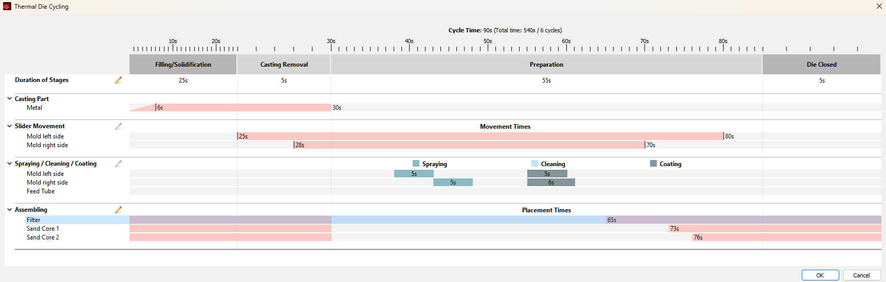
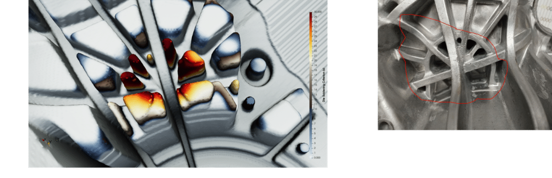
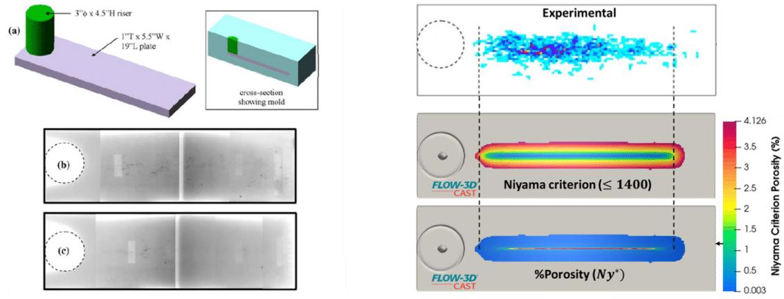
FLOW-3D CAST  에는 캐스팅을 위해 특별히 설계된 광범위하고 강력한 물리적 모델이 포함되어 있습니다. 이러한 특수 모델에는 lost foam casting, non-Newtonian fluids, and die cycling에 대한 알고리즘이 포함됩니다. FLOW-3D CAST 의 강력한 시뮬레이션 엔진과 결함 예측을 위한 새로운 도구는 설계주기를 단축하고 비용을 절감 할 수 있는 통찰력을 제공합니다.

[embedyt] https://www.youtube.com/watch?v=UCjvPcIy4E8[/embedyt]

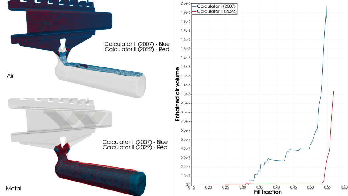
HPDC |Comparison of slow shot profiles and entrained air during a filling simulation |FLOW-3D CAST

Shown is a video comparing two slow shot profiles. The graphs highlight the shot profiles through time and the difference in entrained air between the slow shots. Note the lack of air entrained in shot sleeve with calculated shot profile which yields a much better controlled flow within the shot sleeve.

Coastal & Maritime Applications | FLOW-3D

FLOW-3D는 선박 설계, 슬로싱 다이내믹스, 파동 충격 및 환기 등 연안 및 해양 애플리케이션에 이상적인 소프트웨어입니다. 연안 애플리케이션의 경우 FLOW-3D는 연안 구조물에 심각한 폭풍과 쓰나미 파장의 세부 정보를 정확하게 예측하고 플래시 홍수 및 중요 구조물 홍수 및 손상 분석에 사용됩니다.

[embedyt] https://www.youtube.com/watch?v=0WkmdSpYvM0[/embedyt]
Figure 2. Ink fraction contours for mesh 1 through 4 (left to right) at the following four time steps: (a) 6 µs, (b) 12 µs, (c) 18 µs, and (d) 24 µs.

Coupled CFD-Response Surface Method (RSM) Methodology for Optimizing Jettability Operating Conditions

분사성 작동 조건을 최적화하기 위한 결합된 CFD-Response Surface Method(RSM)

Nuno Couto 1, Valter Silva 1,2,* , João Cardoso 2, Leo M. González-Gutiérrez 3 and Antonio Souto-Iglesias 41
INEGI-FEUP, Faculty of Engineering, Porto University, 4200-465 Porto, Portugal;
nunodiniscouto@hotmail.com
2 VALORIZA, Polytechnic Institute of Portalegre, 7300-110 Portalegre, Portugal; jps.cardoso@ipportalegre.pt
3 CEHINAV, DMFPA, ETSIN, Universidad Politécnica de Madrid, 28040 Madrid, Spain; leo.gonzalez@upm.es
4 CEHINAV, DACSON, ETSIN, Universidad Politécnica de Madrid, 28040 Madrid, Spain;
antonio.souto@upm.es

  • Correspondence: valter.silva@ipportalegre.pt; Tel.: +351-245-301-592

소개

물방울 생성에 대한 이해는 여러 산업 응용 분야에서 매우 중요합니다 [ 1 ]. 잉크젯 프린팅 프로세스는 일반적으로 10 ~ 100 μm [ 1 ] 범위의 독특하고 작은 액적 크기를 특징으로 하며 연속적 또는 충동적 흐름을 사용하여 얻을 수 있습니다 (마지막 방식은 주문형 드롭 (DoD)이라고도 함). 잉크젯).

여러 장점 덕분에 DoD 방법은 산업 환경에서 상당한 수용을 얻고 있습니다 [ 2 ].DoD는 복잡한 프로세스이며 유체 속성, 노즐 형상 및 구동 파형 [ 1 , 3 ]의 세 가지 주요 범주로 분류되는 여러 매개 변수에 따라 달라집니다 .그러나 길이와 시간 척도가 모두 마이크로 오더 [ 4 ] 이기 때문에 실험을하기가 어렵습니다 .

결과적으로 실험 설정은 항상 비용이 많이 들고 복잡하며 CFD (전산 유체 역학)와 같은 고급 수치 접근 방식이 엄격한 요구 사항입니다 [ 5 , 6 ]. VOF (volume-of-fluid) 접근 방식은 액체 분해 및 액적 생성에 대한 다상 공정을 시뮬레이션하기위한 적절한 대안으로 밝혀졌으며 과거 연구에서 그대로 사용되었습니다 [ 7 , 8], 인쇄 프로세스의 맥락에서 전자는 여전히 현재 연구의 주제입니다. 

또한 VOF 체계를 사용하면 단일 운동량 방정식 세트를 해결하고 도메인 전체에 걸쳐 각 유체의 체적 분율을 추적하여 명확하게 정의된 인터페이스로 둘 이상의 혼합 불가능한 유체를 효과적으로 시뮬레이션 할 수 있습니다. Feng [ 9 ]는 VOF 접근 방식을 사용하여 일시적인 유체 인터페이스 변형 및 중단을 효과적으로 추적하는 패키지 FLOW-3D를 사용하여 낙하 배출 중 복잡한 유체 역학 프로세스를 시뮬레이션하는 선구자 작업 중 하나를 수행했습니다.

주요 목표는 볼륨 및 속도와 같은 민감한 변수를 더 잘 이해하면서 장치 개발에서 일반적인 설계 규칙을 구현하는 것이 었습니다. 이러한 종류의 공정과 관련된 주요 질문 중 하나는 안정적인 액적 형성을 위한 작동 범위의 정의입니다.

Fromm [ 10 ]은 Reynolds 수와 Weber 수의 제곱근 비율이 2보다 작으면 안정적인 방울을 생성 할 수 없다는 것을 확인했습니다. 이 무차원 값은 나중에 Z 번호로 알려졌으며 분사 가능성 범위 [ 11 ]를 정의합니다 . 문헌에서 분사 가능성을 위한 Z 간격은 1 ~ 10 [ 12 ], 4 ~ 14 [ 13 ] 또는 0.67 ~ 50 [ 14]을 찾을 수 있습니다. 

이것은 Z 값 만으로는 분사 가능성 조건을 나타낼 수 없음을 분명히 의미합니다. 실제로, 다른 속성을 가진 유체는 다른 인쇄 품질을 나타내면서 동일한 Z 값을 나타낼 수 있습니다. 액적 생성 공정과 해당 분사 성은 주로 전체 공정 품질에 큰 영향을 미치는 매개 변수 세트에 의해 결정됩니다. 

토대 메커니즘을 더 잘 이해하려면 확장 된 작동 조건 및 매개 변수 세트를 고려하여 여러 실험 또는 수치 실행을 수행해야 합니다. DoE (design-of-experiment) 접근 방식과 같은 체계적인 접근 방식이 없으면 이것은 달성하기 매우 어려운 작업이 될 수 있습니다. 최적화 문제를 해결하기 위해 반응 표면 방법을 사용하여 처음으로 체계화된 접근 방식이 개발된 Box and Wilson [ 15 ] 의 선구자 기사 이후 ,이 입증된 방법론은 많은 화학 및 산업 공정[ 16 ] 및 기타 관련 학계에 성공적으로 적용되었습니다.

예를 들어 Silva와 Rouboa [ 17 ]는 직접 메탄올 연료 전지의 출력 밀도에 영향을 미치는 관련 매개 변수를 식별하기 위해 반응 표면 방법론 (RSM)을 사용했습니다. 많은 실제 산업 응용 분야에서 실험 연구는 작동 매개 변수를 조절하기 어렵 기 때문에 제한적이지만 주로 설정을 개발하거나 실험을 실행하는 데 드는 비용이 높기 때문입니다. 

따라서 솔루션은 주요 시스템 응답을 시뮬레이션하고 예측할 수 있는 효과적인 수학적 모델의 개발에 의존합니다. DoE와 같은 최적화 방법론을 수치 모델과 결합하면 비용이 많이 들고 시간이 많이 걸리는 실험을 피하고 다양한 입력 조합을 사용하여 최적의 조건을 얻을 수 있습니다 [ 16 ]. 

실바와 루 보아 [ 18] CFD 프레임 워크 하에서 개발 된 2D Eulerian-Eulerian 바이오 매스 가스화 모델에서 얻은 결과를 RSM과 결합하여 다양한 응용 분야에서 합성 가스를 생성하기 위한 최적의 작동 조건을 찾습니다. 

저자는 입력 요인으로 인한 최상의 응답과 최소한의 변동을 모두 보장하는 작동 조건을 찾을 수 있었습니다. Frawley et al. [ 19 ] CFD 및 DoE 기술 (특히 RSM)을 결합하여 파이프의 팔꿈치에서 고체 입자 침식에 대한 다양한 주요 요인의 영향을 조사하여 침식 예측 모델을 개발할 수 있습니다.우리가 아는 한, DoD 잉크젯 프로세스의 개선 및 더 나은 이해에 적용되는 DoE 접근법 (실험적으로 또는 모든 종류의 수치 모델과 결합)을 구현하는 연구는 없습니다. 선도 기업이 이러한 접근 방식을 적용 할 가능성이 있지만 관련 결과는 민감할 수 있으므로 더 넓은 커뮤니티에서 사용할 수 없습니다. 이 사실은 DoD 잉크젯 공정에서 액적 생성에 대한 여러 매개 변수의 영향을 평가하기 위한 이러한 종류의 연구로서 현재 논문의 영향을 증가 시킬 수 있습니다.

CFD 프레임 워크 내에서 VOF 접근 방식을 사용하여 여러 컴퓨터 실험의 설계를 개발하고 RSM을 분석 도구로 사용했습니다. 충분한 수치 정확도와 수용 가능한 시간 계산 시뮬레이션의 균형을 맞추기 위해 메쉬 수렴 연구가 수행되었습니다. 설계 목적을 위해 점도, 표면 장력, 입구 속도 및 노즐 직경이 입력 요인으로 선택되었습니다. 응답은 break-up 시간과 break-up 길이였습니다.

Figure 1. Schematic of the computational domain
Figure 2. Ink fraction contours for mesh 1 through 4 (left to right) at the following four time steps: (a) 6 µs, (b) 12 µs, (c) 18 µs, and (d) 24 µs.
Figure 3. Comparison between surface tensions at the following four time steps: (a) 6 µs, (b) 12 µs, (c) 18 µs, and (d) 24 µs
Figure 4. Comparison between viscosity values at the following four time steps: (a) 6 μs, (b) 12 μs, (c) 18 μs, and (d) 24 μs.
Figure 5. Comparison between different nozzle diameters at the following four time steps: (a) 6 µs, (b) 12 µs, (c) 18 µs, and (d) 24 µs
Figure 6. Comparison between different inlet velocities at the following four time steps: (a) 6 µs, (b) 12 µs, (c) 18 µs, and (d) 24 µs
Figure 8. Contour response plots for break-up time as a function of (a) surface tension and viscosity, (b) nozzle diameter and viscosity, (c) inlet velocity and viscosity, (d) nozzle diameter and surface tension, (e) inlet velocity and surface tension, and (f) inlet velocity and nozzle diameter.
Figure 12. Break-up length as a function of the We–Ca space (obtained from the 25 runs).

References

  1. Hutchings, I.M.; Martin, G.D. Inkjet Technology for Digital Fabrication; John Wiley & Sons Ltd.: Hoboken, NJ,
    USA, 2013.
  2. Waasdorp, R.; Heuvel, O.; Versluis, F.; Hajee, B.; GhatKesar, M. Acessing individual 75-micron diameter
    nozzles of a desktop inkjet printer to dispense picoliter droplets on demand. RSC Adv. 2018, 8, 14765.
  3. Zhang, H.; Wang, J.; Lu, G. Numerical investigation of the influence of companion drops on drop-ondemand ink jetting. Appl. Phys. Eng. 2012, 13, 584–595.
  4. Dong, H.; Carr, W. An experimental study of drop-on-demand drop formation. Phys. Fluids 2006, 18,
    072102.
  5. Patel, M.; Pericleous, K.; Cross, M. Numerical Modelling of Circulating Fluidized beds. Int. J. Comput.
  6. Fluid Dyn. 1993, 1, 161–176. [CrossRef]
  7. Zhao, X.; Glenn, C.; Xiao, Z.; Zhang, S. CFD development for macro particle simulations. Int. J. Comput.
  8. Fluid Dyn. 2014, 28, 232–249. [CrossRef]
  9. Hasan, M.N.; Chandy, A.; Choi, J.W. Numerical analysis of post-impact droplet deformation for direct-print.
  10. Eng. Appl. Comput. Fluid Mech. 2015, 9, 543–555. [CrossRef]
  11. Ghafouri-Azar, R.; Mostaghimi, J.; Chandra, S. Numerical study of impact and solidification of a droplet
  12. over a deposited frozen splat. Int. J. Comput. Fluid Dyn. 2004, 18, 133–138. [CrossRef]
  13. Feng, J. A General Fluid Dynamic Analysis of Drop Ejection in Drop-on-Demand Ink Jet Devices. J. Imaging
  14. Sci. Technol. 2002, 46, 398–408.
  15. Fromm, J. Numerical Calculation of the Fluid Dynamics of Drop-on-Demand Jets. IBM J. Res. Dev. 1984, 28,
  16. 322–333. [CrossRef]
  17. Nallan, H.; Sadie, J.; Kitsomboonloha, R.; Volkman, S.; Subramanian, V. Systematic Design of Jettable
  18. Nanoparticle-Based Inkjet Inks: Rheology, Acoustics and Jettability. Langmuir 2014, 30, 13470–13477.
  19. [CrossRef] [PubMed]
  20. Reis, N.; Derby, B. Ink Jet Deposition of Ceramic Suspensions: Modelling and Experiments of Droplet Formation;
  21. Chapter in MRS Online Proceeding Library Archive; Cambridge University Press: Cambridge, UK, 2000;
  22. Volume 624, pp. 117–122.
  23. Jang, D.; Kim, D.; Moon, J. Influence of Fluid Physical Properties on Ink-Jet Printability. Langmuir 2009, 25,
  24. 2629–2635. [CrossRef] [PubMed]
  25. Tai, J.; Gan, H.Y.; Liang, Y.N.; Lok, B.K. Control of Droplet Formation in Inkjet Printing Using Ohnesorge
  26. Number Category: Materials and Processes. In Proceedings of the 10th Electronics Packaging Technology
  27. Conference, EPTC, Singapore, 9–12 December 2008; pp. 761–766.
  28. Box, G.; Wilson, K. On the Experimental Attainment of Optimum Conditions. J. R. Stat. Soc. Ser. B 1951, 13,
  29. 1–45.
  30. Silva, V.; Rouboa, A. Optimizing the gasification operating conditions of forest residues by coupling a
  31. two-stage equilibrium model with a response surface methodology. Fuel Process. Technol. 2014, 122, 163–169.
  32. [CrossRef]
  33. Silva, V.; Rouboa, A. Optimizing the DMFC Operating Conditions using a Response Surface Method.
  34. Appl. Math. Comput. 2012, 218, 6733–6743. [CrossRef]
  35. Silva, V.; Rouboa, A. Combining a 2-D multiphase CFD model with a Response Surface Methodology to
  36. optimize the gasification of Portuguese biomasses. Energy Convers. Manag. 2015, 99, 28–40. [CrossRef]
  37. Frawley, P.; Corish, J.; Niven, A.; Geron, M. Combination of CFD and DOE to analyse solid particle erosion
  38. in elbows. Int. J. Comput. Fluid Dyn. 2009, 23, 411–426. [CrossRef]
  39. Morrison, N.F.; Harlen, O.G. Viscoelasticity in inkjet printing. Rheol. Acta 2010, 49, 619–632. [CrossRef]
  40. ANSYS Inc. ANSYS Fluent Tutorial Guide; Release 15.0; ANSYS Inc.: Canonsburg, PA, USA, November 2013.
  41. ANSYS Inc. ANSYS Fluent Theory Guide; Release 17.0; ANSYS Inc.: Canonsburg, PA, USA, January 2016.
  42. Dinsenmeyer, R.; Fourmigué, J.F.; Caney, N.; Marty, P. Volume of fluid approach of boiling flows in
  43. concentrated solar plants. Int. J. Heat Fluid Flow 2017, 65, 177–191. [CrossRef]
  44. Das, S.; Weerasiri, L.D.; Yang, W. Influence of surface tension on bubble nucleation, formation and onset of
  45. sliding. Colloids Surf. A Physicochem. Eng. Asp. 2017, 516, 23–31. [CrossRef]
  46. Du, W.; Zhang, J.; Lu, P.; Xu, J.; Wei, W.; He, G.; Zhang, L. Advanced understanding of local wetting
  47. behaviour in gas-liquid-solid packed beds using CFD with a volume of fluid (VOF) method. Chem. Eng. Sci.
  48. 2017, 170, 378–392. [CrossRef]
  49. Shrestha, S.; Chou, K. A build surface study of Powder-Bed electron beam additive manufacturing by
  50. 3D thermo-fluid simulation and white-light interferometry. Int. J. Mach. Tools Manuf. 2017, 121, 37–49.
  51. [CrossRef]
  52. Zhong, Y.; Fang, H.; Ma, Q.; Dong, X. Analysis of droplet stability after ejection from an inkjet nozzle. J. Fluid
  53. Mech. 2018, 845, 378–391. [CrossRef]
  54. Zhang, X. Dynamics of drop formation in viscous flows. Chem. Eng. Sci. 1999, 54, 1759–1774. [CrossRef]
  55. Calvert, P. Inkjet printing for materials and devices. Chem. Mater. 2001, 13, 3299–3305. [CrossRef]
  56. Kim, C.S.; Park, S.; Sim, W.; Kim, Y.; Yoo, Y. Modelling and characterization of an industrial inkjet head for
  57. micro-patterning on printed circuit boards. Comput. Fluids 2009, 38, 602–612. [CrossRef]
  58. ChemEngineering 2018, 2, 51 19 of 19
  59. Wang, P. Numerical Analysis of Droplet Formation and Transport of a Highly Viscous Liquid. Master’s Thesis,
  60. University of Kentucky, Lexington, KY, USA, 2014.
  61. Zhang, Z.; Xiong, R.; Corr, D.; Huang, Y. Study of Impingement Types and Printing Quality during Laser
  62. Printing of Viscoelastic Alginate Solutions. Langmuir 2016, 32, 3004–3014. [CrossRef] [PubMed]
  63. Derby, B. Inkjet Printing Ceramics: From Drops to Solid. J. Eur. Ceram. Soc. 2011, 31, 2543–2550. [CrossRef]
  64. Kim, E.; Baek, J. Numerical Study on the Effects of Non Dimensional Parameters on Drop-on-Demand
  65. Droplet Formation Dynamics and Printability Range in the up-Scaled Model. Phys. Fluids 2012, 24, 082103.
  66. [CrossRef]
Figure 2. Simulation of droplet separation by EWOD

Non-Linear Electrohydrodynamics in Microfluidic Devices

미세 유체 장치의 비선형 전기 유체 역학

by Jun ZengHewlett-Packard Laboratories, Hewlett-Packard Company, 1501 Page Mill Road, Palo Alto, CA 94304, USAInt. J. Mol. Sci.201112(3), 1633-1649; https://doi.org/10.3390/ijms12031633Received: 24 January 2011 / Revised: 10 February 2011 / Accepted: 24 February 2011 / Published: 3 March 2011

Abstract

Since the inception of microfluidics, the electric force has been exploited as one of the leading mechanisms for driving and controlling the movement of the operating fluid and the charged suspensions. Electric force has an intrinsic advantage in miniaturized devices. Because the electrodes are placed over a small distance, from sub-millimeter to a few microns, a very high electric field is easy to obtain. The electric force can be highly localized as its strength rapidly decays away from the peak. This makes the electric force an ideal candidate for precise spatial control. The geometry and placement of the electrodes can be used to design electric fields of varying distributions, which can be readily realized by Micro-Electro-Mechanical Systems (MEMS) fabrication methods. In this paper, we examine several electrically driven liquid handling operations. The emphasis is given to non-linear electrohydrodynamic effects. We discuss the theoretical treatment and related numerical methods. Modeling and simulations are used to unveil the associated electrohydrodynamic phenomena. The modeling based investigation is interwoven with examples of microfluidic devices to illustrate the applications. 

Keywords: dielectrophoresiselectrohydrodynamicselectrowettinglab-on-a-chipmicrofluidicsmodelingnumerical simulationreflective display

요약

미세 유체학이 시작된 이래로 전기력은 작동 유체와 충전 된 서스펜션의 움직임을 제어하고 제어하는 ​​주요 메커니즘 중 하나로 활용되어 왔습니다. 전기력은 소형 장치에서 본질적인 이점이 있습니다. 전극이 밀리미터 미만에서 수 미크론까지 작은 거리에 배치되기 때문에 매우 높은 전기장을 쉽게 얻을 수 있습니다. 

전기력은 강도가 피크에서 멀어지면서 빠르게 감소하기 때문에 고도로 국부화 될 수 있습니다. 이것은 전기력을 정밀한 공간 제어를 위한 이상적인 후보로 만듭니다.

전극의 기하학적 구조와 배치는 다양한 분포의 전기장을 설계하는 데 사용될 수 있으며, 이는 MEMS (Micro-Electro-Mechanical Systems) 제조 방법으로 쉽게 실현할 수 있습니다. 

이 논문에서 우리는 몇 가지 전기 구동 액체 처리 작업을 검토합니다. 비선형 전기 유체 역학적 효과에 중점을 둡니다. 이론적 처리 및 관련 수치 방법에 대해 논의합니다. 모델링과 시뮬레이션은 관련된 전기 유체 역학 현상을 밝히는 데 사용됩니다. 모델링 기반 조사는 응용 분야를 설명하기 위해 미세 유체 장치의 예와 결합됩니다. 

키워드 : 유전 영동 ; 전기 유체 역학 ; 전기 습윤 ; 랩 온어 칩 ; 미세 유체 ; 모델링 ; 수치 시뮬레이션 ; 반사 디스플레이

Droplet processing array Droplet based BioFlip
igure 1. Example of droplet-based digital microfluidics architecture. Above is an elevation view showing the layered structure of the chip. Below is a diagram illustrating the system (Adapted from [4]).
Figure 2. Simulation of droplet separation by EWOD
Figure 2. Simulation of droplet separation by EWOD. The top two figures illustrate the device configuration. Electric voltages are applied to all four electrodes embedded in the insulating material. The bottom left figure shows transient simulation solution. It illustrates the process of separating one droplet into two via EWOD. The bottom right figure shows the electric potential distribution inside the device. The color indicates the electric potential; the iso-potential surfaces are also drawn. The image shows the electric field is absent within the droplet body indicating the droplet is either conductive or highly polarizable.
Figure 4. Transient sequence of the Taylor cone formation
Figure 4. Transient sequence of the Taylor cone formation: simulation and experiment comparison. Experimental images are shown in the top row. Simulation results are shown in the bottom row. Their correspondence is indicated by the vertical alignment (Adapted from [4]).
Figure 6. Simulation of charge screening effect using a parallel-plate cell
Figure 6. Simulation of charge screening effect using a parallel-plate cell. Top-left image shows the electric current as function of time and driving voltage, top-right image shows the evolution of the species concentration as function of time and space, the bottom image shows the electric current readout after switching the applied voltage.
Figure 7. Transient simulation of electrohydrodynamic instability and the development of the cellular convective flow pattern.
Figure 3. Simulation of dielectrophoresis driven axon migration
Figure 3. Simulation of dielectrophoresis driven axon migration. The set of small images on the left shows a transient simulation of single axon migration under an electric field generated by a pin electrode. The image on the right is a snapshot of a simulation where two axons are fused by dielectrophoresis using a pin electrode. Axons are outlined in white. Also shown are the iso-potential curves.

References

  1. Muller, RS. MEMS: Quo vadis in century XXI. Microelectron. Eng 200053(1–4), 47–54. [Google Scholar]
  2. Reyes, DR; Iossifidis, D; Auroux, PA; Manz, A. Micro total analysis systems. 1. Introduction, theory, and technology. Anal.Chem 200274, 2623–2636. [Google Scholar]
  3. Levy, U; Shamai, R. Tunable optofluidic devices. Microfluid. Nanofluid 20084, 97–105. [Google Scholar]
  4. Zeng, J; Korsmeyer, FT. Principles of droplet electrohydrodynamics for lab-on-a-chip. Lab Chip 20044, 265–277. [Google Scholar]
  5. Fair, RB. Digital microfluidics: Is a true lab-on-a-chip possible? Microfluid. Nanofluid 20073, 245–281. [Google Scholar]
  6. Pollack, MG; Fair, RB; Shenderov, AD. Electrowetting-based actuation of liquid droplets for microfluidic applications. Appl. Phys. Lett 200077(11), 1725–1726. [Google Scholar]
  7. Peykov, V; Quinn, A; Ralston, J. Electrowetting: A model for contact-angle saturation. Colloid Polym. Sci 2000278, 789–793. [Google Scholar]
  8. Verheijen, HJJ; Prins, MWJ. Reversible electrowetting and trapping of charge: Model and experiments. Langmuir 199915, 6616–6620. [Google Scholar]
  9. Mugele, F; Baret, J. Electrowetting: From basics to applications. J. Phys. Condens. Matter 200517, R705–R774. [Google Scholar]
  10. Quilliet, C; Berge, B. Electrowetting: A recent outbreak. Curr. Opin. Colloid Interface Sci 20016, 34–39. [Google Scholar]
  11. Probstein, RF. Physicochemical Hydrodynamics; Wiley: New York, NY, USA, 1994. [Google Scholar]
  12. Koo, J; Kleinstreuer, C. Liquid flow in microchannels: Experimental observations and computational analyses of microfluidics effects. J. Micromech. Microeng 200313, 568–579. [Google Scholar]
  13. Hu, G; Li, D. Multiscale phenomena in microfluidics and nanofluidics. Chem. Eng. Sci 200762, 3443–3454. [Google Scholar]
  14. Haus, HA; Melcher, JR. Electromagnetic Fields and Energy; Prentice-Hall: Englewood Cliffs, NJ, USA, 1989. [Google Scholar]
  15. Leal, LG. Laminar Flow and Convective Transport Processes: Scaling Principles and Asymptotic Analysis; Butterworth-Heinemann: Oxford, UK, 1992. [Google Scholar]
  16. Collins, RT; Harris, MT; Basaran, OA. Breakup of electrified jets. J. Fluid Mech 2007588, 75–129. [Google Scholar]
  17. Sista, R; Hua, Z; Thwar, P; Sudarsan, A; Srinivasan, V; Eckhardt, A; Pollack, M; Pamula, V. Development of a digital microfluidic platform for point of care testing. Lab Chip 20088, 2091–2104. [Google Scholar]
  18. Zeng, J. Modeling and simulation of electrified droplets and its application to computer-aided design of digital microfluidics. IEEE Trans. Comput. Aid. Des. Integr. Circ. Syst 200625(2), 224–233. [Google Scholar]
  19. Walker, SW; Bonito, A; Nochetto, RH. Mixed finite element method for electrowetting on dielectric with contact line pinning. Interface. Free Bound 201012, 85–119. [Google Scholar]
  20. Eck, C; Fontelos, M; Grün, G; Klingbeil, F; Vantzos, O. On a phase-field model for electrowetting. Interface. Free Bound 200911, 259–290. [Google Scholar]
  21. Gascoyne, PRC; Vykoukal, JV. Dielectrophoresis-based sample handling in general-purpose programmable diagnostic instruments. Proc. IEEE 200492(1), 22–42. [Google Scholar]
  22. Jones, TB; Gunji, M; Washizu, M. Dielectrophoretic liquid actuation and nanodroplet formation. J. Appl. Phys 200189(3), 1441–1448. [Google Scholar]
  23. Sretavan, D; Chang, W; Keller, C; Kliot, M. Microscale surgery on single axons. Neurosurgery 200557(4), 635–646. [Google Scholar]
  24. Pohl, HA; Crane, JS. Dielectrophoresis of cells. Biophys. J 197111, 711–727. [Google Scholar]
  25. Melcher, JR; Taylor, GI. Electrohydrodynamics: A review of the role of interfacial shear stresses. Annu. Rev. Fluid Mech 19691, 111–146. [Google Scholar]
  26. Saville, DA. Electrohydrodynamics: The taylor-melcher leaky-dielectric model. Annu. Rev. Fluid Mech 199729, 27–64. [Google Scholar]
  27. Schultz, GA; Corso, TN; Prosser, SJ; Zhang, S. A fully integrated monolithic microchip electrospray device for mass spectrometry. Anal. Chem 200072(17), 4058–4063. [Google Scholar]
  28. Killeen, K; Yin, H; Udiavar, S; Brennen, R; Juanitas, M; Poon, E; Sobek, D; van de Goor, T. Chip-MS: A polymeric microfluidic device with integrated mass-spectrometer interface. Micro Total Anal. Syst 2001, 331–332. [Google Scholar]
  29. Dukhin, SS. Electrokinetic phenomena of the second kind and their applications. Adv. Colloid Interface Sci 199135, 173–196. [Google Scholar]
  30. Wang, Y-C; Stevens, AL; Han, J. Million-fold preconcentration of proteins and peptides by nanofluidic filter. Anal. Chem 200577(14), 4293–4299. [Google Scholar]
  31. Kim, SJ; Wang, Y-C; Han, J. Nonlinear electrokinetic flow pattern near nanofluidic channel. Micro Total Anal. Syst 20061, 522–524. [Google Scholar]
  32. Comiskey, B; Albert, JD; Yoshizawa, H; Jacobson, J. An electrophoretic ink for all-printed reflective electronic displays. Nature 1998394(6690), 253–255. [Google Scholar]
  33. Beunis, F; Strubbe, F; Neyts, K; Bert, T; De Smet, H; Verschueren, A; Schlangen, L. P-39: Electric field compensation in electrophoretic ink display. In Proceedings of the Twenty-fifth International Display Research Conference—Eurodisplay 2005; Edinburgh, UK, 19–22 2005; pp. 344–345. [Google Scholar]
  34. Strubbe, F; Verschueren, ARM; Schlangen, LJM; Beunis, F; Neyts, K. Generation current of charged micelles in nonaqueous liquids: Measurements and simulations. J. Colloid Interface Sci 2006300, 396–403. [Google Scholar]
  35. Hsu, MF; Dufresne, ER; Weitz, DA. Charge stabilization in nonpolar solvents. Langmuir 200521, 4881–4887. [Google Scholar]
  36. Hayes, RA; Feenstra, BJ. Video-speed electronic paper based on electrowetting. Nature 2003425, 383–385. [Google Scholar]
  37. Chakrabarty, K; Su, F. Digital Microfluidic Biochips: Synthesis, Testing, and Reconfiguration Techniques; CRC Press: Boca Raton, FL, USA, 2006. [Google Scholar]
  38. Chakrabarty, K; Fair, RB; Zeng, J. Design tools for digital microfluidic biochips: Towards functional diversification and more than Moore. IEEE Trans.CAD Integr. Circ. Syst 201029(7), 1001–1017. [Google Scholar]
Evaluation of the Wind Effects on the Iron-Ore Stock Pile

Energy

Energy

전 세계 에너지 부문의 엔지니어는 전산 유체 역학(CFD)을 통해 해결책을 찾기 위해 광범위한 프로세스에서 매일 복잡한 설계 문제에 직면합니다. 특히 자유 표면 흐름과 관련이 높은 이러한 문제의 대부분은 FLOW-3D가 매우 정확한 분석을 제공하여 문제 해결에 적합합니다.

  • 공해에서 컨테이너 내부의 연료 또는화물 슬로싱 / Fuel or cargo sloshing inside containers on the high seas
  • 해양 플랫폼에 대한 파도 효과 / Wave effects on offshore platforms
  • 6 자유도 모션을 받는 분리 장치의 성능 최적화 / Performance optimization for separation devices undergoing 6 DOF motion
  • 파동 에너지 포착 장치 / Design of devices to capture energy from waves

Energy Case Studies

천연자원이 계속 감소함에 따라, 대체 자원과 방법을 탐구하고 가능한 한 효과적으로 현재 공급량을 사용하고 있습니다. 엔지니어는 사고를 예방하고 채굴 및 기타 에너지 수확 기법으로 인한 환경적 영향을 평가하기 위해 FLOW-3D를 사용합니다.

Tailing Breach Simulation – CFD Analysis with FLOW-3D

점성이 높은 유체, 비 뉴턴 흐름, 슬러리 또는 심지어 세분화 된 흐름의 형태를 취할 수있는 많은 채광 응용 프로그램의 잔여 물인 테일링은 악명 높은 시뮬레이션 전제를 제공합니다. FLOW-3D  는 비 뉴턴 유체, 슬러리 및 입상 흐름에 대한 특수 모델을 포함하여 이러한 분석을 수행하는 데 필요한 모든 도구를 제공합니다. FLOW-3D 의 자유 표면 유동 모델링 기능 과 결합되어  이러한 어렵고 환경 적으로 민감한 문제에 대한 탁월한 모델링 솔루션을 제공합니다.

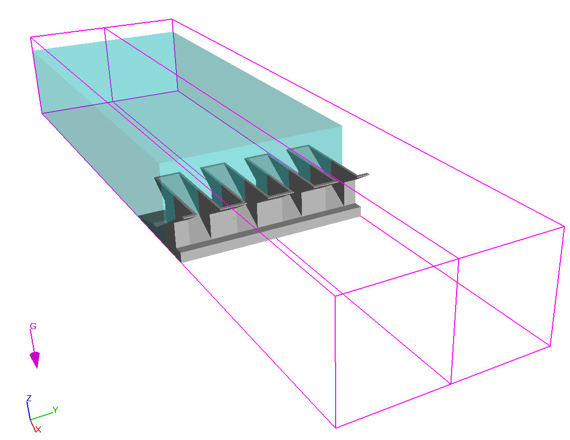
관련 응용 분야에는 바람 강제 분석에 따른 광석 비축 더미 먼지 드리프트가 포함되며, 여기서 FLOW-3D 의 드리프트 플럭스 모델을 통해 엔지니어는 광석 침착 및 유입 패턴과 개선 솔루션의 효과를 연구 할 수 있습니다.

액화와 기계적 방해가 물과 같은 뉴턴 흐름과는 대조적으로 입자 흐름의 매우 독특한 속성 인 결국 저절로 멈추는 위반의 동적 특징의 일부라는 점에 유의하십시오.

[embedyt] https://www.youtube.com/watch?v=Fp9QJ92QX2M[/embedyt]

오일 및 가스 분리기

FLOW-3D  는 기름과 물과 같은 혼합 불가능한 유체를 모델링 할 수 있으며 개방 된 환경 (주변 공기)과 관련된 구성 요소 간의 뚜렷한 인터페이스를 정확하게 추적 할 수 있습니다. 유체는 전체 도메인에 영향을 미치는 역학으로 인해 자유롭게 혼합 될 수 있습니다. 시간이 지남에 따라 유체는 연속 상과 분산 상 간의 드리프트 관계에 따라 다시 분리됩니다. 중력 분리기의 성능은 CFD 모델링을 통해 향상 될 수 있습니다.

  • 기체 및 액체 흐름의 균일성을 개선하고 파도에 의한 슬로싱으로 인한 오일과 물의 혼합을 방지하기 위해 용기 입구 구성을 개발합니다.
  • 유압 효율 및 분리 성능에 대한 내부 장비의 영향을 결정합니다.
  • 작동 조건 변화의 영향 측정
  • 소규모 현상 (다상 흐름, 방울, 입자, 기포)을 정확하게 모델링

생산 파이프 | Production Pipes

생산에 사용되는 공정 파이프의 청소 과정에서 유체가 위로 흘러도 고밀도 입자가 침전될 수 있습니다. 침전 입자를 포착하도록 장치를 설계 할 수 있습니다. 파이프 중앙에 있는 “버킷”이 그러한 잠재적 장치중 하나 입니다. 흐름 변위로 인해 버킷 외부의 상류 속도는 고밀도 입자에 대한 침전 속도보다 높으며 버킷 내부에 모여 있습니다. 표시된 디자인에서 버킷 주변의 상향 유체 속도는 입자 안정화 속도보다 높습니다. 이로 인해 입자가 버킷과 파이프 벽 사이의 틈새를 통해 빠져 나갈 수 없습니다. 따라서 시뮬레이션된 입자는 버킷을 통과하여 아래에 정착하지 않습니다.

[embedyt] https://www.youtube.com/watch?v=3evNXA-I3mM[/embedyt]

파동 에너지 장치 모델링 | Modeling Wave Energy Devices

포인트 흡수 장치 | Point Absorber Devices

이 시뮬레이션은 상단에 부력이있는 구형 구조가있는 점 흡수 장치를 보여 주며, 들어오는 파도의 볏과 골과 함께 위아래로 이동합니다. FLOW-3D 의 움직이는 물체 모델은 x 또는 y 방향으로의 움직임을 제한하면서 z 방향으로 결합 된 움직임을 허용하는 데 사용됩니다. 진폭 5m, 파장 100m의 스톡 스파를 사용했다. RNG 모델은 파도가 점 흡수 장치와 상호 작용할 때 발생하는 난류를 포착하는 데 사용되었습니다. 예상대로 많은 난류 운동 에너지가 장치 근처에서 생성됩니다. 플롯은 난류로 인해 장치 근처의 복잡한 속도 장의 진화로 인해 질량 중심의 불규칙한 순환 운동을 보여줍니다.

다중 플랩, 하단 경첩 파동 에너지 변환기 | Multi-Flap, Bottom-Hinged Wave Energy Converter

진동하는 플랩은 바다의 파도에서 에너지를 추출하여 기계 에너지로 변환합니다. Arm은 물결에 반응하여 피벗된 조인트에 장착된 진자로 진동합니다. 플랩을 배열로 구성하여 다중 플랩 파동 에너지 변환기를 만들 수 있습니다. 아래 상단에 표시된 CFD 시뮬레이션에서 3 개의 플랩 배열이 시뮬레이션됩니다. 모든 플랩은 바닥에 경첩이 달려 있으며 폭 15m x 높이 10m x 두께 2m입니다. 어레이는 30m 깊이에서 10 초의 주파수로 4m 진폭파에서 작동합니다. 시뮬레이션은 중앙 평면을 따라 복잡한 속도 등 가면을 보여줍니다. 이는 한 플랩이 어레이 내의 다른 플랩에 미치는 영향을 연구하는 데 중요합니다. 3 개의 플랩이 유사한 동적 동작으로 시작하는 동안 플랩의 상호 작용 효과는 곧 동작을 위상에서 벗어납니다. 유사한 플랩 에너지 변환기가 오른쪽 하단에 표시됩니다. 이 시뮬레이션에서 플랩은 가장 낮은 지점에서 물에 완전히 잠 깁니다. 이러한 에너지 변환기를 Surface Piercing 플랩 에너지 변환기라고합니다. 이 두 시뮬레이션 예제는 모두 미네르바 역학 .

[embedyt] https://www.youtube.com/watch?v=Jnf9EGuHiV0[/embedyt] [embedyt] https://www.youtube.com/watch?v=9NzewSmADuk[/embedyt] [embedyt] https://www.youtube.com/watch?v=CcID1xzKTTo[/embedyt]

진동 수주 | Oscillating Water Column

진동하는 수주는 부분적으로 잠긴 중공 구조입니다. 그것은 물의 기둥 위에 공기 기둥을 둘러싸고 수면 아래의 바다로 열려 있습니다. 파도는 물 기둥을 상승 및 하강시키고, 차례로 공기 기둥을 압축 및 감압합니다. 이 갇힌 공기는 일반적으로 기류의 방향에 관계없이 회전 할 수 있는 터빈을 통해 대기로 흐르게 됩니다. 터빈의 회전은 전기를 생성하는 데 사용됩니다.

아래의 CFD 시뮬레이션은 진동하는 수주를 보여줍니다. FLOW-3D에서 포착한 물리학을 강조하기 위해 중공 구조에서 물기둥이 상승 및 하강하는 부분만 모델링  합니다. 시뮬레이션은 다른 파형 생성 선택을 제외하고 유사한 결과를 전달합니다. 아래의 시뮬레이션은 웨이브 유형 경계 조건을 사용하는 반면 그 아래의 시뮬레이션은  움직이는 물체 모델  을 사용하여 실험실에서 수행한 것처럼 차례로 웨이브를 생성하는 움직이는 플런저를 생성합니다. 각 시뮬레이션에 대해 속이 빈 구조의 압력 플롯이 표시됩니다. 결국 그 압력에 기초하여 터빈이 회전 운동으로 설정되기 때문에 챔버에서 얼마나 많은 압력이 생성되는지 아는 것이 중요합니다.

[embedyt] https://www.youtube.com/watch?v=byyFin6xZlw[/embedyt] [embedyt] https://www.youtube.com/watch?v=wnJMRvp5UCc[/embedyt]

사례 연구

eadership-in-energy-and-environmental-design

Architects Achieve LEED Certification in Sustainable Buildings

LEED (Leadership in Energy and Environmental Design)는 제 3자가 친환경 건축물 인증을 제공하는 자발적 인증 시스템입니다.

FLOW-3D는 보고타(콜롬비아)의 사무실 건물에서 “IEQ-Credit2–환기 증가”라는 신뢰를 얻는 데 큰 도움을 주었습니다. 이러한 인정을 받기 위해서는 실외 공기가 ASHRAE의 표준 비율인 30%를 초과한다는 것을 증명해야만 합니다. 이 건물에서 실외 공기는 태양 광선에 의해, 가열되는 지붕 위의 2개의 유리 굴뚝에 의해 발생되는 온도 차이에 의해 발생하는 열 부력의 영향으로 제공됩니다. 이것은 바람이 불지 않는 조건에서 이루어져야 합니다.

Comparing HVAC System Designs

최근 프로젝트에서 Tecsult의 HVAC(난방, 냉방 및 환기)시스템 엔지니어는 강력한 에어컨 시스템의 두 가지 다른 구성을 고려해야 했고 노동자들에게 어떤 것이 가장 쾌적함을 제공하는지 보여주기를 원했습니다. FLOW-3D는 대체 설계를 시뮬레이션하고 비교하는 데 사용되었습니다.

이 발전소는 대형(길이 90m, 너비 33m, 높이 26m)건물로 변압기, 전력선, 조명 등 열 발생 장비를 갖추고 있습니다. 에어컨 시스템의 목적은 건물 내 최대 온도를 35ºC로 제한하는 것입니다. 디퓨저가 하부 레벨에 위치하고 천장 근처의 환기구가 있기 때문에 천장 근처에서 최대 공기 온도가 발생하고 바닥 레벨은 반드시 몇도 더 낮습니다.

Modeling velocity of debris types

Debris Transport in a Nuclear Reactor Containment Building

이 기사는 FLOW-3D가 원자력 시설에서 봉쇄 시설의 성능을 모델링하는데 사용된 방법을 설명하며, Alion Science and Technology의 Tim Sande & Joe Tezak이 기고 한 바 있습니다.

가압수형 원자로 원자력 발전소에서 원자로 노심을 통해 순환되는 물은 약 2,080 psi 및 585°F의 압력과 온도로 유지되는 1차 배관 시스템에 밀폐됩니다. 수압이 높기 때문에 배관이 파손되면 격납건물 내에 여러 가지 이물질 유형이 생성될 수 있습니다. 이는 절연재가 장비와 균열 주변 영역의 배관에서 떨어져 나가기 때문에 발생합니다. 생성될 수 있는 다양한 유형의 이물질의 일반적인 예가 나와 있습니다(오른쪽).

Evaluation of the Wind Effects on the Iron-Ore Stock Pile

Evaluation of the Wind Effects on the Iron-Ore Stock Pile

바람이 개방형 골재 저장소에 미치는 영향은 전 세계적으로 환경 문제가 되고 있습니다. 2.7km철골 저장소 부지에서 이런 문제가 관찰되었습니다. 이 시설은 철도 운송차량를 통해 광석을 공급받는데, 이 운송차량은 자동 덤프에 의해 비워집니다. 그런 다음 이 광석은 일련의 컨베이어와 이송 지점을 통과하여 저장 장소중 하나로 운송됩니다. 비산먼지 배출은 풍력이 비축된량에 미치는 영향의 결과로 관찰된 결과입니다.

관련 기술자료


Schematic view of the experimental set-up

Short-time numerical simulation of ultrasonically assisted electrochemical removal of strontium from water

September 2023 DOI:10.30955/gnc2023.00436 Conference: 18th International Conference on Environmental Science and Technology CEST2023, 30 August to 2 September 2023, Athens, ...
The Fastest Laptops for 2024

FLOW-3D 수치해석용 노트북 선택 가이드

2024년 가장 빠른 노트북 PCMag이 테스트하는 방법 소개 : 기사 원본 출처: https://www.pcmag.com/picks/the-fastest-laptops CFD를 수행하기 위한 노트북 선정 기준은 별도로 ...
Figure 1. US bath modified as an EC reactor

물에서 초음파를 이용한 전기화학적 스트론튬 제거에 대한 단시간 수치 시뮬레이션

전기화학 반응기에 대한 3D 수치 시뮬레이션 및 측정을 사용하여 동시 초음파 처리 유무에 관계없이 물에서 스트론튬 제거 효율을 분석했습니다. 초음파는 ...
Figure 1. Three-dimensional finite element model of local scouring of semi-exposed submarine cable.

반노출 해저케이블의 국부 정련과정 및 영향인자에 대한 수치적 연구

Numerical Study of the Local Scouring Process and Influencing Factors of Semi-Exposed Submarine Cables by Qishun Li,Yanpeng Hao *,Peng Zhang,Haotian Tan,Wanxing Tian,Linhao ...
Validity evaluation of popular liquid-vapor phase change models for cryogenic self-pressurization process

극저온 자체 가압 공정을 위한 인기 있는 액체-증기 상 변화 모델의 타당성 평가

액체-증기 상 변화 모델은 밀폐된 용기의 자체 가압 프로세스 시뮬레이션에 매우 큰 영향을 미칩니다. Hertz-Knudsen 관계, 에너지 점프 모델 및 ...
Figure 3. Different parts of a Searaser; 1) Buoy 2) Chamber 3) Valves 4) Generator 5) Anchor system

데이터 기반 방법을 활용한 재생 가능 에너지 변환기의 전력 및 수소 생성 예측 지속 가능한 스마트 그리드 사례 연구

Fatemehsadat Mirshafiee1, Emad Shahbazi 2, Mohadeseh Safi 3, Rituraj Rituraj 4,*1Department of Electrical and Computer Engineering, K.N. Toosi University of ...
Figure 7. Comparison of Archimedean screw power performances P(W) for Q = 0.15 m3 /s and 0.30m3 /s and angles of orientation 22ο & 32ο .

CFD Simulations of Tubular Archimedean Screw Turbines Harnessing the Small Hydropotential of Greek Watercourses

Alkistis Stergiopoulou 1, Vassilios Stergiopoulos 21 Institut für Wasserwirtschaft, Hydrologie und Konstruktiven Wasserbau, B.O.K.U. University, Muthgasse 18, 1190 Vienna, (actually ...
Figure 1: Drawing of the experimental set-up, Figure 2: Experimental tank with locations of temperature sensors

실험 및 수치 시뮬레이션에 기반한 극저온 추진제 탱크 가압 분석

Analyses of Cryogenic Propellant Tank Pressurization based upon Experiments and Numerical SimulationsCarina Ludwig? and Michael Dreyer***DLR - German Aerospace Center, ...
Figure 1: Mold drawings

3D Flow and Temperature Analysis of Filling a Plutonium Mold

플루토늄 주형 충전의 3D 유동 및 온도 분석 Authors: Orenstein, Nicholas P. [1] Publication Date:2013-07-24Research Org.: Los Alamos National Lab ...
Fig. 6 LH2 isotherms at 1020 s.

액체-수소 탱크를 위한 결합된 열역학-유체-역학 솔루션

Coupled thermodynamic-fluid-dynamic solution for a liquid-hydrogen tank G. D. Grayson Published Online:23 May 2012 https://doi.org/10.2514/3.26706 Read Now Tools Share Introduction ...

주조 분야

Metal Casting

주조제품, 금형의 설계 과정에서 FLOW-3D의 사용은 회사의 수익성 개선에 직접적인 영향을 줍니다.
(주)에스티아이씨앤디에서는  FLOW-3D를 통해 해결한 수많은 경험과 전문 지식을 엔지니어와 설계자에게 제공합니다.

품질 및 생산성 문제는 빠른 시간 안에 시뮬레이션을 통해 예측 가능하므로 낮은 비용으로 해결 할수 있습니다. FLOW-3D는 특별히 주조해석의 정확성 향상을 위한 다양한 설계 물리 모델들을 포함하고 있습니다.

이 모델에는 Lost Foam 주조, Non-newtonian 유체 및 금형의 다이싸이클링 해석에 대한 알고리즘 등을 포함하고 있습니다. 시뮬레이션의 정확성과 주조 제품의 품질을 향상시키고자 한다면, FLOW-3D는 여러분들의 이러한 요구를 충족시키는 제품입니다.

Ladle Pour Simulation by Nemak Poland Sp. z o.o.


Models
  • Cooling Channels
  • Core Gas
  • Thermal Stress Evolution
  • More Modeling Capabilities
Case Studies

관련 기술자료

The Fastest Laptops for 2024

FLOW-3D 수치해석용 노트북 선택 가이드

2024년 가장 빠른 노트북 PCMag이 테스트하는 방법 소개 : 기사 원본 출처: https://www.pcmag.com/picks/the-fastest-laptops CFD를 수행하기 위한 노트북 선정 기준은 별도로 ...
The experimental layout

Strength Prediction for Pearlitic Lamellar Graphite Iron: Model Validation

펄라이트 라멜라 흑연 철의 강도 예측: 모델 검증 Vasilios Fourlakidis, Ilia Belov, Attila Diószegi Abstract The present work provides validation ...
Fig. 1. Protection matt over the scour pit.

Numerical study of the flow at a vertical pile with net-like scourprotection matt

그물형 세굴방지 매트를 사용한 수직말뚝의 유동에 대한 수치적 연구 Minxi Zhanga,b, Hanyan Zhaoc, Dongliang Zhao d, Shaolin Yuee, Huan Zhoue,Xudong ...
그림 2.1 가공 후 부품 보기

1 m/s보다 빠른 속도에서 액체 금속의 움직임 연구

ESTUDIO MOVIMIENTO DE METAL LIQUIDO A VELOCIDADES MAYORES DE 1 M/S Author: Primitivo Carranza TormeSupervised by :Dr. Jesus Mª Blanco ...
Figure 14. Defects: (a) Unmelt defects(Scheme NO.4);(b) Pores defects(Scheme NO.1); (c); Spattering defect (Scheme NO.3); (d) Low overlapping rate defects(Scheme NO.5).

Molten pool structure, temperature and velocity
flow in selective laser melting AlCu5MnCdVA alloy

용융 풀 구조, 선택적 온도 및 속도 흐름 레이저 용융 AlCu5MnCdVA 합금 Pan Lu1 , Zhang Cheng-Lin2,6,Wang Liang3, Liu Tong4 ...
Figure 4.24 - Model with virtual valves in the extremities of the geometries to simulate the permeability of the mold promoting a more uniformed filling

Optimization of filling systems for low pressure by Flow-3D

Dissertação de MestradoCiclo de Estudos Integrados Conducentes aoGrau de Mestre em Engenharia MecânicaTrabalho efectuado sob a orientação doDoutor Hélder de ...
Figure 1: Mold drawings

3D Flow and Temperature Analysis of Filling a Plutonium Mold

플루토늄 주형 충전의 3D 유동 및 온도 분석 Authors: Orenstein, Nicholas P. [1] Publication Date:2013-07-24Research Org.: Los Alamos National Lab ...
Figure 5: 3D & 2D views of simulated fill sequence of a hollow cylinder at 1000 rpm and 1500 rpm at various time intervals during filling.

Computer Simulation of Centrifugal Casting Process using FLOW-3D

Aneesh Kumar J1, a, K. Krishnakumar1, b and S. Savithri2, c 1 Department of Mechanical Engineering, College of Engineering, Thiruvananthapuram, ...
Fig. 1. (a) Dimensions of the casting with runners (unit: mm), (b) a melt flow simulation using Flow-3D software together with Reilly's model[44], predicted that a large amount of bifilms (denoted by the black particles) would be contained in the final casting. (c) A solidification simulation using Pro-cast software showed that no shrinkage defect was contained in the final casting.

AZ91 합금 주물 내 연행 결함에 대한 캐리어 가스의 영향

TianLiabJ.M.T.DaviesaXiangzhenZhucaUniversity of Birmingham, Birmingham B15 2TT, United KingdombGrainger and Worrall Ltd, Bridgnorth WV15 5HP, United KingdomcBrunel Centre for Advanced Solidification ...
Gating System Design Based on Numerical Simulation and Production Experiment Verification of Aluminum Alloy Bracket Fabricated by Semi-solid Rheo-Die Casting Process

Gating System Design Based on Numerical Simulation and Production Experiment Verification of Aluminum Alloy Bracket Fabricated by Semi-solid Rheo-Die Casting Process

반고체 레오 다이 캐스팅 공정으로 제작된 알루미늄 합금 브래킷의 수치 시뮬레이션 및 생산 실험 검증을 기반으로 한 게이팅 시스템 설계 ...
FLOW-3D CAST 2025R1

FLOW-3D CAST

FLOW-3D CAST 2025R1은 주조 엔지니어가 복잡한 비철 주조에서 더 나은 품질, 효율성 및 정밀도를 달성할 수 있도록 지원합니다. 이번 릴리스에는 응고 및 수축 모델, HPDC의 샷 슬리브 모델, 밸브 모델에 대한 개선 사항이 포함되어 있습니다.

응고 수축 모델 개선 사항
이번 신제품에는 새로운 EXODUS 형식의 다공성 출력이 수정된 개선된 응고 수축 모델이 포함되어 있어 사용자가 다공성 분석과 해석을 간소화할 수 있습니다. 이제 다공성 출력에는 분해된 수축 다공성이 포함되어 엔지니어가 누출 경로를 더 잘 시각화할 수 있도록 도와줍니다.

샷 슬리브의 응고된 금속 처리 개선
고압 다이캐스팅(HPDC)에서는 샷 슬리브의 초기 응고로 인해 완성된 주조물의 콜드 셧 및 오선과 같은 결함이 발생할 수 있습니다. 이제 사용자는 다공성 기반 응고 모델을 사용하여 샷 슬리브에서 응고된 금속의 움직임을 포착할 수 있으며, 충전 시 훨씬 더 정확한 열 프로파일을 제공합니다.

EXODUS 파일 형식의 새로운 다공성 표현은 단일 다공성 출력에서 금속의 다공성뿐만 아니라 해상된 수축을 더 잘 설명합니다.

개선된 밸브 모델
FLOW-3D CAST의 밸브와 통풍구 부품은 주조 어셈블리의 환기 시스템을 모델링하는 데 사용되며, 이는 주조 부품의 결함을 제거하는 데 매우 중요할 수 있습니다. 이제 사용자는 밸브와 통풍구에서 배출될 수 있는 목표 금속 부피를 지정하여 개선된 밸브 모델을 통해 최종 결함 위치를 보다 정확하게 예측할 수 있습니다.

새로운 밸브 모델은 금속이 밸브를 통해 배출될 수 있도록 하여, 흐름 결함이 어디로 가는지 더 정확하게 표현합니다 (아래쪽)

FLOW-3D CAST 2024R1은 영구 금형 주조를 위한 여러 가지 개선 사항을 포함하고 있으며, 그 중 첫 번째는 Thermal die cycling 시뮬레이션에서 보다 시각적으로 편리한 냉각 채널 설정입니다. 이를 통해 냉각 채널 타이밍 설정을 더 쉽게 하고 입력 오류의 가능성을 줄일 수 있습니다. 이 개선 사항은 각 냉각 채널이 활성화되는 시점과 관련 속성을 쉽게 확인할 수 있도록 합니다.

Cooling channel setup
냉각 채널은 이제 다른 공정 타이밍과 함께 표시되어 복잡한 시스템을 간단하고 시각적으로 표현합니다.

또한, 간단한 스프레이/금형 처리 모델을 확장하여 캐비티뿐만 아니라 파팅 라인에도 스프레이할 수 있는 옵션을 추가했습니다. 이를 통해 이러한 유형의 금형 처리 방식을 쉽게 그리고 현실적으로 표현할 수 있어 더 나은 열 예측을 할 수 있습니다. 유사하게, 이제 Thermal die cycling 시뮬레이션 중에 플런저의 움직임을 고려하여 열 예측의 정확성을 향상시켰습니다.

또 다른 개발 사항은 초기 단계 금형 설계에서 더 빠른 열 해석을 제공하면서도 해석의 정확도를 유지할 수 있도록 설계되었습니다. 이는 새로운 열 전달 모드를 기하학적 형태에 대해 활성화하여 사용합니다.

FLOW-3D CAST 2024R1에는 두 가지 새로운 출력이 추가되었습니다. 첫 번째는 금형에 대한 특정 열 전달로, 금형으로 전달되는 열의 속도를 저장하고 금형의 다양한 위치에서 필요한 냉각 능력에 대한 통찰을 제공합니다. 두 번째 출력은 공동 발생 하중으로, 공동 손상이 발생할 가능성이 있는 영역을 표시합니다.

금형으로의 열전달량 표현
Cavitation load
공동 발생 하중

마지막으로, 사용자 기대에 더 맞도록 기존 모델에 두 가지 조정을 추가했습니다. 첫 번째는 밸브가 가장 가까운 open volume에 적용되도록 수정하여, 금형 표면이 실수로 밸브를 비활성화하는 가능성을 없앴습니다. 두 번째 조정은 모델을 사용할 때 플런저 가속도의 기본 한계를 더 현실적으로 설정한 것입니다. 이전의 기본값은 노이즈가 발생될 가능성이 있었습니다.

새로운 결과 파일 형식

FLOW-3D POST 2023R2는 EXODUS II 형식을 기반으로 하는 완전히 새로운 결과 파일 형식을 도입하여 더 빠른 후처리를 가능하게 합니다. 이 새로운 파일 형식은 크고 복잡한 시뮬레이션의 후처리 작업에 소요되는 시간을 크게 줄이는 동시에(평균 최대 5배!) 다른 시각화 도구와의 연결성을 향상시킵니다.

FLOW-3D POST 2023R2 에서 사용자는 이제 flsgrf , EXODUS II 또는 flsgrf 및 EXODUS II 파일 형식 으로 선택한 데이터를 쓸 수 있습니다 . 새로운 EXODUS II 파일 형식은 각 객체에 대해 유한 요소 메쉬를 활용하므로 사용자는 다른 호환 가능한 포스트 프로세서 및 FEA 코드를 사용 하여 FLOW-3D 결과를 열 수도 있습니다. 새로운 워크플로우를 통해 사용자는 크고 복잡한 사례를 신속하게 시각화하고 임의 슬라이싱, 볼륨 렌더링 및 통계를 사용하여 보조 정보를 추출할 수 있습니다.

새로운 결과 파일 형식은 솔버 엔진의 성능을 저하시키지 않으면서 flsgrf 에 비해 시각화 작업 흐름에서 놀라운 속도 향상을 자랑합니다.

FLOW-3D POST의 표면 LIC
FLOW-3D POST 의 새로운 EXODUS II 파일 형식 및 Surface LIC 표현의 예

이 흥미로운 새로운 개발은 결과 분석의 속도와 유연성이 향상되어 사용자에게 원활한 시뮬레이션 경험을 제공합니다. FLOW-3D POST 의 새로운 시각화 기능 에 대해 자세히 알아보세요 .

정수압 초기화

사용자가 사전 정의된 금속 영역에서 정수압을 초기화해야 하는 경우가 종종 있습니다. 크고 복잡한 시뮬레이션에서는 정수압 솔버의 수렴 속도가 느려지는 경우가 있습니다. FLOW-3D CAST 2023R2는 정수압 솔버의 성능을 크게 향상시켜 전처리 단계에서 최대 6배 빠르게 수렴할 수 있도록 해줍니다.

새로운 TDC(열 다이 사이클링) 모델

열 다이 사이클링 - 샷 슬리브
새로운 Thermal Die Cycling 모델로 예측된 ​​샷 슬리브의 온도 분포

FLOW-3D CAST 2023R2 의 재설계된 열 다이 사이클링(TDC) 모델은 고압 다이 캐스팅 및 기타 영구 금형 주조 공정의 프로세스 시트와 더 잘 일치하는 더 간단하고 직관적인 설정 프로세스를 제공합니다. 

이제 TDC 시퀀스는 충전 단계의 시작 부분 에서 시작되어 하위 프로세스 전반에 걸쳐 시간에 따른 냉각/가열 라인 정의에 대한 더 높은 정확성과 정렬을 제공합니다. 향상된 스프레이 냉각 모델을 통해 사용자는 부품별로 처리 일정을 정의할 수 있을 뿐만 아니라 스프레이, 세척 및 코팅 처리에 대한 옵션을 처방할 수 있습니다. 슬라이더 동작도 포함되며 이제 냉각 채널과 가열 요소가 슬라이더와 함께 이동합니다. 

이러한 기능은 다양한 단계, 일정, 이동, 처리 및 조립 단계를 보여주는 깔끔하고 직관적인 프로세스 개요를 제공하는 새로운 Thermal Die Cycling 대화 상자를 통해 제어됩니다.

FLOW-3D CAST의 열 다이 사이클링 대화상자
FLOW-3D CAST 의 새로운 Thermal Die Cycling 대화 상자

이러한 개발은 개선된 열 솔루션뿐만 아니라 TDC와 관련된 공정의 응고 및 납땜에 대한 더 나은 예측을 촉진합니다.

FLOW-3D CAST 2023R1 의 새로운 기능

FLOW-3D 소프트웨어 제품군의 모든 제품은 2023R1에서 IT 관련 개선 사항을 받았습니다. 

FLOW-3D CAST 2023R1은 이제 Windows 11 및 RHEL 8을 지원합니다. Linux 설치 프로그램은 누락된 종속성을 보고하도록 개선되었으며 더 이상 루트 수준 권한이 필요하지 않으므로 설치가 더 쉽고 안전해집니다. 그리고 워크플로를 자동화한 분들을 위해 입력 파일 변환기에 명령줄 인터페이스를 추가하여 스크립트 환경에서도 워크플로가 업데이트된 입력 파일로 작동하는지 확인할 수 있습니다.

FLOW-3D CAST 2023R1 의 고급 기능을 통해 사용자는 다음을 수행할 수 있습니다.

  • 기가캐스팅 제작 시 등 샷 성능 최적화
  • 툴링 마모 해결
  • 고급 탄소강 및 저합금강 주조 시뮬레이션
  • 거시적 분리의 효과를 설명합니다.

플런저 모션 개선

우리는 슬로우 샷 계산기를 개선하여 정확성을 높이고, 공기 혼입을 줄이며, 낮은 충전 수준을 더 잘 처리할 수 있도록 유효성 범위를 확장했습니다. 또한 사용자 인터페이스를 간소화했으며 향상된 슬로우 샷 계산기와 결합하여 인상적인 결과를 제공합니다. 이제 플런저 위치 또는 시간 기반 정의에서 슬로우 샷 계산기의 데이터를 쉽게 사용할 수 있습니다. 새로운 계산기는 또한 슬로우 샷이 끝날 때 혼입되는 공기를 크게 줄이는 세련된 샷 프로필을 제공합니다.

슬로우 샷 계산기 개선
2007년 슬로우 샷 계산기와 2022년 버전 비교. 슬로우 샷이 끝나면 새 계산기를 사용하여 동반 공기량이 감소하는 것을 확인하십시오.

확장된 PQ 2 분석

대형 주조는 계산 비용이 많이 들고 기가 주조는 시뮬레이션 소프트웨어를 한계까지 밀어붙일 수 있습니다. 속도 경계 조건이나 금속 입력을 사용하여 샷 슬리브와 플런저를 근사화하는 것은 런타임을 줄이는 유용한 단순화 방법입니다. 그러나 PQ 

2 분석 없이는 HPDC 기계가 한계에 가깝게 작동하고 예상대로 작동하지 않아 부품 품질을 위협하는지 알 수 없습니다. 

우리는 매우 유능한 PQ 2 분석을 수행 하고 이를 금속 입력 및 속도 경계 조건에 적용하여 이 문제를 해결했습니다. 이는 가장 크고 가장 복잡한 주조에서도 충전 정확도를 유지하면서 처리 시간을 크게 줄이는 것을 의미합니다.

Mold Erosion Prediction | FLOW-3D CAST

주조 금형과 다이는 기계적 스트레스 요인을 포함한 다양한 이유로 마모됩니다. 기존 전단 하중 측정법은 이 마모를 연구할 때 도움이 되지만 지금까지는 금형에 대한 금속의 충돌을 설명하지 못했고 모래 주조 금형에 포함된 모래의 최종 위치를 예측할 수 없었습니다. 이 문제를 해결하기 위해 우리는 이 마모 메커니즘을 더 잘 이해할 수 있도록 새로운 출력을 추가했습니다. 새로운 출력에는 이러한 유형의 침식이 발생할 가능성이 있는 지역과 모래 함유물의 예상 위치가 표시됩니다.

다이 솔더링 예측

알루미늄 주조에 사용되는 영구 다이는 용융된 알루미늄이 다이의 철과 결합하여 화학적 마모를 겪게 되며, 이는 부품 품질뿐만 아니라 다이의 수명과 유지 관리 요구 사항에 영향을 미치는 땜납을 형성합니다. 이 마모 메커니즘의 중요성으로 인해 우리는 납땜의 위치와 심각도를 모두 예측하는 모델을 구축하게 되었습니다.

다이 솔더링 시뮬레이션
시뮬레이션된 솔더(왼쪽)와 관찰된 솔더(오른쪽, 빨간색). 사진은 다이에 관한 것이지만 시뮬레이션에서는 부품을 보여주기 때문에 이미지가 거울처럼 보입니다.

화학 기반 탄소 및 저합금강 응고 모델

우리의 장기 개발 목표 중 하나의 결과는 석출 반응, 응고 및 재용해 경로, 미세 구조 특징 및 결함을 정확하게 설명하는 탄소강 및 저합금강에 대한 강력한 화학 기반 응고 모델 입니다. 이 모델은 또한 중요한 3상 포정반응과 델타 페라이트에서 오스테나이트로의 전이로 인한 대량 수축과 관련된 결함을 설명합니다.

이 모델은 실험과의 탁월한 일치를 보여주며, 예를 들어 과포정 합금이 응고가 끝날 때 페라이트 영역을 개발할 수 있는 이유와 같은 비직관적이고 시간 의존적인 동작에 대한 통찰력을 제공합니다.

수축 예측 검증

거시 분리 예측

대규모 분리는 주조품의 품질과 다운스트림 처리에 중요한 영향을 미칠 수 있으므로 이를 화학 기반 응고 모델에 추가했습니다. 이 모델은 매크로 분리 관련 결함이 발생할 수 있는 위치를 예측하므로 캐스팅 전에 이를 예측하고 완화할 수 있습니다.

시뮬레이션 대 실험 강철 주조
강철 주조에 대한 실험과 시뮬레이션 결과를 비교합니다. WT Adams, Jr. 및 KW Murphy, “주강 주물에서 라이저 아래의 심각한 화학 물질 분리를 방지하기 위한 최적의 완전 접촉 상단 라이저”, AFS Trans., 88(1980), pp. 389-404

FLOW-3D CAST 2022R2 의 새로운 기능

FLOW-3D CAST 2022R2 제품군 출시로 Flow Science는 FLOW-3D CAST 의 워크스테이션과 HPC 버전을 통합하여 단일 노드 CPU 구성에서 다중 노드 병렬 고성능 컴퓨팅 실행. 추가 개발에는 점탄성 흐름을 위한 새로운 로그 형태 텐서 방법, 지속적인 솔버 속도 성능 개선, 고급 냉각 채널 및 팬텀 구성요소 제어, 개선된 동반 공기 기능이 포함됩니다.

통합 솔버

우리는  FLOW-3D 제품을 단일 통합 솔버로 마이그레이션하여 로컬 워크스테이션이나 고성능 컴퓨팅 하드웨어 환경에서 원활하게 실행했습니다.

많은 사용자가 노트북이나 로컬 워크스테이션에서 모델을 실행하지만, 고성능 컴퓨팅 클러스터에서도 더 큰 모델을 실행합니다. 2022R2 릴리스에서는 통합 솔버를 통해 사용자가 HPC 솔루션의 OpenMP/MPI 하이브리드 병렬화와 동일한 이점을 활용하여 워크스테이션과 노트북에서 실행할 수 있습니다.

성능 확장의 예
증가하는 CPU 코어 수를 사용한 성능 확장의 예
메쉬 분해의 예
OpenMP/MPI 하이브리드 병렬화를 위한 메시 분해의 예

솔버 성능 개선

멀티 소켓 워크스테이션

다중 소켓 워크스테이션은 이제 매우 일반적이며 대규모 시뮬레이션을 실행할 수 있습니다. 새로운 통합 솔버를 사용하면 이러한 유형의 하드웨어를 사용하는 사용자는 일반적으로 HPC 클러스터 구성에서만 사용할 수 있었던 OpenMP/MPI 하이브리드 병렬화를 활용하여 모델을 실행할 수 있어 성능이 향상되는 것을 확인할 수 있습니다.

낮은 수준의 루틴으로 향상된 벡터화 및 메모리 액세스

대부분의 테스트 사례에서 10~20% 정도의 성능 향상이 관찰되었으며 일부 사례에서는 20%를 초과하는 런타임 이점이 나타났습니다.

정제된 체적 대류 안정성 한계

시간 단계 안정성 제한은 모델 런타임의 주요 동인이며, 2022R2에서는 새로운 시간 단계 안정성 제한인 3D 대류 안정성 제한을 숫자 위젯에서 사용할 수 있습니다. 실행 중이고 대류가 제한된(cx, cy 또는 cz 제한) 모델의 경우 새 옵션은 일반적인 속도 향상을 30% 정도 보여줍니다.

압력 솔버 프리컨디셔너

경우에 따라 까다로운 흐름 구성의 경우 과도한 압력 솔버 반복으로 인해 실행 시간이 길어질 수 있습니다. 이러한 어려운 경우 2022R2에서는 모델이 너무 많이 반복되면 FLOW-3D가 자동으로 새로운 사전 조절기를 활성화하여 압력 수렴을 돕습니다. 테스트의 런타임은 1.9에서 335까지 더 빨라졌습니다!

점탄성 유체에 대한 로그 형태 텐서 방법

점탄성 유체에 대한 새로운 솔버 옵션을 사용자가 사용할 수 있으며 특히 높은 Weissemberg 수에 효과적입니다.

활성 시뮬레이션 제어 확장

능동 시뮬레이션 제어 기능이 확장되어 연속 주조 및 적층 제조 응용 분야에 일반적으로 사용되는 팬텀 개체는 물론 주조 및 기타 여러 열 관리 응용 분야에 사용되는 냉각 채널에도 사용됩니다.

팬텀 물체 속도 제어의 예
연속 주조 응용 분야에 대한 가상 물체 속도 제어의 예
동적 열 제어의 예
융합 증착 모델링 애플리케이션을 위한 동적 열 제어의 예
동적 냉각 채널 제어의 예
산업용 탱크 적용을 위한 동적 냉각 채널 제어의 예

FLOW-3D CAST 아카이브 의 새로운 기능

FLOW-3D CAST는 다양한 금속 주조 해석이 가능한 완벽한 열유동 해석 프로그램으로, 매우 정확한 모델링과 다기능성, 사용 용이성 및 고성능 클라우드 컴퓨팅 기능을 결합한 최첨단 금속 주조 해석 시뮬레이션 플랫폼입니다. 모든 금속 주조 공정에 대해 FLOW-3D CAST는  빠르고 직관적인 해석이 가능한 작업 공간을 제공합니다. 11개 공정에 대한 Workspace, 강력한 후처리, 충진 예측, 응고 및 결함 분석을 통해 FLOW-3D CAST는 최적의 주조 제품 설계에 필요한 도구와 로드맵을 모두 제공합니다.

FLOW-3D Cast는 거의 모든 주조 공정을 모델링 할 수 있도록 설계되었습니다. FLOW-3D Cast의 매우 정확한 유동 및 응고 결과는 표면 산화물, 혼입된 공기, 매크로 및 미세 다공성과 같은 중요한 주조 결함을 포착합니다. 다른 특별한 모델링 기능으로는 로봇 스프레이 냉각 및 윤활, 샷 슬리브 흐름 프로필, 스퀴즈 핀 및 열 응력을 모델링 할 수있는 열 다이 사이클링이 있습니다.

최적화된 시뮬레이션 설계를 통해 개발 시간을 단축하고 출시 시간을 단축하며 수율을 높일 수 있습니다. FLOW-3D CAST를 사용하면 설계 및 개발 비용을 절감할 수 있습니다.

FLOW-3D CAST Continuous Casting WorkspaceFLOW-3D CAST Gravity Die Casting Workspace
FLOW-3D CAST HPDC WorkspaceFLOW-3D CAST Investment Casting WorkspaceFLOW-3D CAST Low Pressure Sand Casting Workspace
FLOW-3D CAST Low Pressure Die Casting WorkspaceFLOW-3D CAST Sand Casting WorkspaceFLOW-3D CAST Sand Core Making Workspace
Lost Foam CastingFLOW-3D CAST Tilt Pour Casting
HPDC Oxides Simulation | FLOW-3D CAST
BMW Injector Casting Process – Innovative ingate system for gravity casting
Continuous Slab Casting | FLOW-3D CAST
Horizontal Centrifugal Pipe Casting | FLOW-3D CAST
수자원/수처리/환경분야

수자원 분야

Water & Environmental

FLOW-3D는 작은 하수 처리 시스템부터 대형 수력 발전 프로젝트까지 수처리 및 환경 산업에 직면한 광범위한 문제를 해결할 수 있는 뛰어난 CFD 소프트웨어 입니다. FLOW-3D는 시뮬레이션의 복잡성을 감소시키고 최적의 솔루션에 대해 노력을 집중할 수 있도록 해줍니다. 이를 통해 통해 파악된 가치 있는 통찰력은 귀하의 상당한 시간과 비용을 절약 할 수 있습니다.

실제 지형을 적용하여 3차원 shallow water hybrid model을 이용한 댐 붕괴 시뮬레이션

FLOW-3D는 자유표면 흐름이 있는 수치해석 알고리듬에 의해 유동의 표면이 시공간적으로 변하는 모사를 위한 이상적인 도구라고 할 수 있습니다. 자유 표면은 물과 공기 같은 높은 비율의 밀도 변화를 가지는 유체들 사이의 특정한 경계를 일컫습니다. 자유 표면 흐름을 모델링하는 것은 일반적인 유동방정식과 난류 모델이 결합된 고급 알고리즘을 필요로 합니다. 이 기능은 FLOW-3D로 하여금 침수 구조에 의해 형성된 방수, 수력 점프 및 수면 변화의 흐름의 궤적을 포착 할 수 있습니다.


Bibliography & Technical Data

CSO-Result

합류식 하수관 월류 유동 전환 구조물 해석

폭우 시 하수관의 용량 부족은 월류(Overflow)를 초래하고, 이는 하천 오염으로 이어집니다. 설계 오류는 이러한 문제를 악화시킬 수 있습니다. FLOW-3D HYDRO와 ...
flip bucket spillway

Flip Bucket Spillway

고속으로 흐르는 물의 충격과 침식은 예측하기 어렵고, 설계 오류는 곧 댐의 안전을 위협할 수 있습니다. FLOW-3D HYDRO와 함께라면 이러한 위험을 ...
ShowerHead

샤워기 내부 유동 해석

🚿 샤워기 내부 유동, 과연 눈에 보이지 않는 물의 움직임은 어떨까요? 저희가 FLOW-3D HYDRO를 활용하여 샤워기 내부의 복잡한 유동을 해석한 ...
Baffle

Baffle Drop Structure

Baffle Drop Structure 설계, 정말 안전할까요?경사수로에서 발생하는 난류와 침식은 예측하기 어렵고, 설계 오류는 곧 재앙적인 결과를 초래할 수 있습니다.FLOW-3D HYDRO와 ...
Schematic view of the experimental set-up

Short-time numerical simulation of ultrasonically assisted electrochemical removal of strontium from water

September 2023 DOI:10.30955/gnc2023.00436 Conference: 18th International Conference on Environmental Science and Technology CEST2023, 30 August to 2 September 2023, Athens, ...
Flood

Study of a Tailings Dam Failure Pattern and Post-Failure Effects under Flooding Conditions

폐석댐 붕괴 패턴 및 홍수 조건에서의 붕괴 후 영향 연구 Zhong Gao, Jinpeng Liu, Wen He, Bokai Lu, Manman Wang, ...
F-BW

Determination of Formulae for the Hydrodynamic Performance of a Fixed Box-Type Free Surface Breakwater in the Intermediate Water

중간 수심에서 고정된 박스형 자유 수면 방파제의 유체역학적 성능 공식을 결정하기 위한 연구 Guoxu Niu, Yaoyong Chen, Jiao Lu, Jing ...
Wave

Three-Dimensional Simulations of Subaerial Landslide-Generated Waves: Comparing OpenFOAM and FLOW-3D HYDRO Models

지표 산사태로 발생한 파랑의 3차원 시뮬레이션: OpenFOAM과 FLOW-3D HYDRO 모델 비교 Ramtin Sabeti, Mohammad Heidarzadeh, Alessandro Romano, Gabriel Barajas Ojeda ...
Weir

Discharge Formula and Hydraulics of Rectangular Side Weirs in the Small Channel and Field Inlet

소규모 수로 및 유입구에서의 직사각형 측면 위어의 유량 공식 및 수리학 Yingying Wang, Mouchao Lv, Wen’e Wang, Ming Meng Abstract ...

Three-dimensional flow structure in a confluence-bifurcation unit

합류 분기 유닛의 3차원 유동 구조 Di Wang, Xiaoyong Cheng, Zhixuan Cao, Jinyun Deng Abstract Enhanced understanding of flow structure ...


FLOW-3D Water & Environmental Brochure (FSI) Bibliography

Models

  • Air Entrainment
  • Hybrid Shallow Water/3D Flow
  • Sediment Scour
  • Turbulence
  • More Modeling Capabilities

Case Studies

  • Evaluating Hydraulic Energy Losses and Total Hydraulic Head with FLOW-3D‘s Flux Baffles
  • Modeling Commercial Aquaculture Systems
  • Modeling Local Bridge Scour during Flood Event

Conference Proceedings

Figure 1: PAC-UPC laboratory canal bend in operation.

1D, 2D AND 3D MODELING OF A PAC-UPC LABORATORY CANAL BEND

PAC-UPC 실험실 운하 굴곡의 1D, 2D 및 3D 모델링

Manuel Gómez, FLUMEN Research Institute. Technical University of Catalonia. Jordi Girona, 1-3. 08034
Barcelona. Spain. Phone: +00 (34) 93 401 64 75
manuel.gomez@upc.edu
Eduardo Martínez1
, FLUMEN Research Institute. Technical University of Catalonia. Jordi Girona, 1-3.
08034 Barcelona. Spain. Phone: +00 (34) 93 401 64 75
eduardo.martinez-gomariz@upc.edu

KEY WORDS
Irrigation Canals 3D, 2D and 1D computation, gate, weir, curved reach.

ABSTRACT 

개요 본 연구는 카탈로니아 공과 대학의 Campus Nord에 위치한 PAC-UPC 운하의 수력 학적 거동을 분석하기 위해 수행되었습니다. 이것은 실제 관개 운하의 모델을 구성하며, 2003 년에 건설 된 이후 관개 운하 및 제어 알고리즘과 관련된 다양한 연구 및 박사 논문에 사용되었습니다. 점유 공간을 최소화하기 위해 뱀 모양의 운하는 자체를 따라 약간의 굴곡을 생성하여 뚜렷한 수면 수준이 상승합니다. 아 임계 체제가 있어도 세부 사항을 완벽하게 분석해야하는 명확하게 관찰 할 수 있습니다. 이러한 접근 방식을 수행하기 위해 각각 1D, 2D 및 3D 분석을 고려하는 방식이 제안되었습니다. 고려 된 코드는 Hec-Ras (1D), Iber (2D) 및 Flow 3D로 각 코드의 결과를 비교 연구했습니다. 이 비교는 각각의 한계를 강조합니다. 이전에 알려진 바와 같이 3D 결과는 흐름 거동에 대한 훨씬 더 많은 정보를 제공하여 z 방향으로 형성된 재순환 영역과 소용돌이를 분석 할 수도 있습니다. 흐름 분석 후 최종 결과는 예를 들어 계측기 (레벨 센서)의 최적 위치 또는 구조의 형상에 대한 수정과 관련하여 향후 작업 및 연구를 위해 운하에서 가능한 개선을 제안합니다.

INTRODUCTION AND SCOPE OF THE STUDY

자유 표면 흐름은 특히 수로 및 하강 역학과 관련하여 수력 학에서 광범위하게 연구되는 흐름 유형입니다. 그들의 연구는 1D, 2D 또는 3D 수치 모델링을 통해 이루어질 수 있으며, 이는 하천 또는 수로의 수력 분석을 수행하는 가장 일반적인 1D 모델링입니다. 더 높은 계산 비용을 가정하더라도 2 차원 분석이 점점 더 많이 구현되지만 아직 3D 분석은 너무 자주 고려되지 않습니다. 2 차원 분석은 두 방향의 속도 성분이 세 번째 영역 (예 : 델타 영역)보다 우세한 영역에서 수행되고 3 차원 분석은 명확하게 3 차원 효과 (테디 및 복잡한 현상)가있는 국소 영역에서 수행됩니다. 더 높은 계산 비용이 필요합니다. 현재 바르셀로나의 Campus Nord 수압 연구소에는 제어 알고리즘을 테스트하는 운하 인 PAC-UPC 운하가 있습니다. 이 운하는 문과 배설물이있는 실제 관개 운하의 측면을 재현하려고합니다. 2003 년에 지어졌으며 그 이후로 관개 운하와 관련된 여러 박사 및 석사 논문이 발표되었으며 특히 운하 제어 알고리즘의 개발과 함께 발표되었습니다. 이러한 알고리즘은 수로 수 문의 자동화를 목표로하여 모든 수로 도달 흐름에서 수위를 선택한 지점에서 규정 할 수 있으며 수문은 선택한 지점 (오프 테이크)에서 원하는 수위와 수위를 보장하기 위해 이동합니다.

처음부터 굽힘 영역에서 국부적 인 과도 상승이 관찰되었습니다. 운하가 실제 관개 운하와 실제 관개 운하 제어 문제를 재현하는 것을 목표로하기 때문에 이러한 과도 상승을 연구하고 운하 시설에 대한 결과를 확인해야했습니다. 이러한 흐름 거동은 시각적으로 명확하게 관찰 할 수 있으며 이는 낮은 속도에서도 유압 현상이 발생 함을 시사합니다. 수문 아래를 통과하기 전에 수평면의 굽힘을 따라 급격한 변화가있는 흐름 궤적과 수직면에서 유선의 90 ° 회전이 생성됩니다. 이러한 경로는 속도 성분이 세 방향 모두에서 중요하며 한 방향 (1D) 또는 두 방향 (2D)에서만 널리 퍼져 있음을 나타냅니다.

Figure 1: PAC-UPC laboratory canal bend in operation.

그림 1은 자유 표면에서 발생하는 불규칙성을 보여줍니다. 대부분은 굴곡 옆에 있고 하류 수문과 둑의 영향으로 나타납니다. 유압 문제에 적용되는 수치 적 방법은 점점 더 많은 컴퓨팅 파워를 제공하며 시장에는 많은 오픈 소스를 포함하여 다양한 소프트웨어가 있습니다. 3D 문제의 모델링 및 시뮬레이션을위한 강력한 도구는 Flow-3D 프로그램입니다. 이 도구는이 연구에서보고 된 연구에 사용되었으며 분석은 Hec-Ras 및 Iber와 같은 오픈 소스 소프트웨어로 보완되었습니다 [6]. 따라서 1 차원, 2 차원 및 3 차원 코드를 통해 상세한 흐름 분석을 수행했습니다. 이 연구의 주요 목적은 흐름이 굴곡, 위어 및 하류 수문을 만날 때이 운하의 흐름 패턴을 자세히 이해하는 것입니다. 분명히 이러한 유동 거동 지식은 필요한 경우 측정 기기의 재배치 또는 유동 거동에 필요한 경우 굽힘 형태의 복원과 같은 2 차적이지만 덜 중요한 목표로 이어질 수 있습니다. 1D, 2D 및 3D 수치 모델링 도구를 사용하면 이러한 도구의 결과를 비교하고 각 접근 방식의 장단점을 연구 할 수 있습니다. 따라서 이 연구의 목표는

요약 :

-PAC-UPC 실험실 운하 곡선 도달에서 발생하는 흐름의 수력학적 거동을 자세히 이해합니다.
-1D, 2D 및 3D 모델링 비교 및 필요에 따라 적합성 분석.
-해석, 흐름의 수력 학적 거동, 수로 계기 재배치 가능성 및 수로 구조의 모양 수정.

  1. 운하 설명
    Canal PAC-UPC는 “Canal de Pruebas de Algoritmos de Control (Test Canal Algorithms Control)-Universitat Politècnica de Catalunya (Technical University of Catalonia)”의 머리 글자입니다. 이름에서 알 수 있듯이 관개 운하 제어, 운하 계측, 운하 모델링, 수질 측정 등의 기본 및 응용 연구를 위해 특별히 설계된 실험실 운하입니다. Campus Nord UPC의 물리적 모델 실험실에서 구현됩니다.

그 구조는 실제 관개 운하의 특성을 재현하여 나타날 수 있는 문제를 제어하기 위한 것입니다. 이러한 이유로 최대 시간 지연을 생성하기 위해 가능한 최대 길이와 경사가 0 인 운하가 건설되었습니다. 점유 면적을 최적화 하는 현재 뱀 모양을 만들기 위해 실험실의 제한된 공간이 필요하게 되었습니다. 길이 220m, 폭 44cm, 높이 1m의 직사각형 단면으로, 총 바닥 면적은 약 22.5m x 5.4m입니다.

Figure 2: Detailed scheme of the whole PAC-UPC canal.

As shown in Figure 2, the elements of the installation are as follows:

  • A header reservoir
  • 3 vertical sluice gates (G1, G3 and G5)
  • 4 rectangular weirs (W1, W2, W3 and W4)
  • 9 Level sensors (LS1 to LS9)
  • 1 control room

GENERAL APPROACH TO THE PROBLEM

3.1 소개

PAC-UPC 운하 및보다 구체적으로 위어 (W1) 및 수문 (G3)이 위치한 운하 굴곡에 대한 연구, 그림 2에 따라.
계측 요구, 특히 레벨 센서의 배치는 이러한 근관 굴곡 연구에 특별한 관심을 가졌습니다. 이 운하 설계를 사용하면 유선이 유속이 더 높을수록 운하 곡선 도달을 통해 복잡한 경로를 수행하고 수위가 국부적으로 증가하고 제어하기가 어렵고 세부 사항이없는 한 정확성을 결정하기가 어렵습니다. 연구가 이루어집니다. PAC-UPC 운하의 이러한 굴곡에서 유동의 불확실한 거동과 레벨 센서의 최상의 배치에 대한 연구를 기반으로 데이터 수집 실험 캠페인이 수행되었습니다. 이것은 10 가지 다른 조합 (흐름, 수문 개구부 및 위어의 높이)에 대한 운하 굴곡 전체에 걸쳐 10 개 지점의 깊이 측정으로 구성되었습니다. 이러한 실험 데이터는이 연구에 제시된 모델을 보정하고 검증하는 데 기본적이고 필수적입니다. 1D, 2D 및 3D 수치 모델링은 다음과 같은 두 가지 목적으로 제안됩니다. 1)이 굴곡 영역을 자세히 연구하여 운하 전체에 기기 배치를보다 정확하게 결정할 수 있습니다. 2) 1D, 2D 및 3D 모델 결과를 비교 분석하여이 사례 연구에 가장 좋은 정보를 제공하는 모델을 결정합니다.

3.2 연구 구역 설명

4 개의 굴곡부 중 3 개는 직사각형 위어 (W1, W2 및 W3)를 포함하여 운하의 한쪽에 있습니다. 위어를 보여주는 굴곡은 더 복잡한 흐름 패턴을 생성하는 굴곡이므로 (위어가 작동중인 경우) 자세한 연구가 더 흥미롭습니다. 이 경우 W1 weir가있는 굽힘이 선택되었습니다. 이 연구의 결과는 다른 굴곡에 대해 외삽 될 것이라는 점을 언급해야 합니다. 그림 2는 수위 측정과 유압 및 계측 요소가 있는 연구 영역을 강조 표시합니다. 또한 부드러운 곡선은 없지만 둥근 모서리 없이 90º에서 갑자기 방향이 변경됩니다. 연구 영역은 2D 및 3D 모델 도면으로 재현 되었으며, 각각 Iber 및 Flow-3D 프로그램으로 내보내졌습니다. 그림 3은 측정 지점의 위치와 상세한 3D 도면이 포함 된 2D 플랜트 맵을 보여줍니다.

Figure 3: Study zone. Measurement points in 2D drawing (left) and 3D drawing (right).

3.3 Case Studies

이하 내용은 원문을 참고하시기 바랍니다.

Figure 1. Right: Absolute velocities in the vertical sluice gate fish pass. Level difference between the pools is 0.20 m. Left: Isosurface of the surface structure (blue), Right and left: Isosurface of absolute velocity 1.50 m/s (yellow)

Success Criterion for Fish Passages |수력 발전소 물고기 통로

São Roque 수력 발전소 물고기 통로

이 기사는 Matthias Haselbauer, RMD Consult  및 Carlos Barreira Martinez (  Minas Gerais 연방 대학교) 가 기고했습니다  .

브라질에서는 지난 150 년 동안 지표수의 사용이 지속적으로 증가했습니다. 항행성을 유지하고, 수력을 생성하고, 홍수를 방지하기 위해 자연 흐름을 방해하는 많은 장애물과 우회로가 세워졌습니다. 강에 서식하는 물고기 및 기타 작은 동물은 이러한 변화로 고통 받습니다. 일부 종의 멸종 시점까지 어류 수가 크게 감소한 것이 관찰되었습니다. 어류, 조류 및 포유류 개체수가 동시에 감소함에 따라 먹이 사슬에 대한 인간의 엄청난 영향이 분명해졌습니다.

강을 물고기를 위해 개방하기 위해 브라질에 많은 수의 물고기 통로가 건설되었지만 생물학적 및 기술적 측면에서 효율성이 떨어지는 경우가 많았습니다. 종종 1 차원적이고 경험적인 가정을 사용하여 설계된 통로의 흐름 상황은 과도한 선택과 열악한 위치를 초래합니다. 전통적인 1 차원 디자인의 물고기 통로와 달리 오늘날 더 적절한 도구를 사용할 수 있습니다. CFD (전산 유체 역학) 시뮬레이션을 사용하면 평균 속도 필드 뿐만 아니라 물고기 통로의 유용성에 상당한 영향을 미치는 과도 흐름 효과를 조사 할 수 있습니다. 최적의 결과를 얻으려면 설계 프로세스에서 수력 학적 고려 사항과 생물학적 고려 사항의 결합이 필수적입니다.

이 연구에서는주기적인 수직 수문 물고기 통로 내부의 난류 응집 구조에 대해 논의합니다. 길이가 4.50m이고 너비가 각각 3.30 인 두 개의 웅덩이 사이에서 흐름은 0.50m의 확장이 있는 작은 수직 개구부를 통과해야 합니다 (그림 1). 

CFD 시뮬레이션은 FLOW-3D 로 수행되었습니다 . 흐름 방향의 주기적 경계 조건에서 달성 가능한 해상도는 약 2.5cm입니다. 두 웅덩이 사이의 수면 Δh의 레벨 차이는 20cm였다. 따라서 절대 속도의 최대 값은 약 2m / s ≈ Δh * 2g입니다. 전체 위치 에너지는 운동 에너지로 변환되고 나중에 풀에서 소멸됩니다. 제트가 벽에서 분리되는 고속 영역이 형성됩니다.

절대 속도 수문 물고기 통과
그림 1. 오른쪽 : 수직 수문 물고기 통과의 절대 속도. 수영장 사이의 레벨 차이는 0.20m입니다. 왼쪽 : 표면 구조의 등면 (파란색), 오른쪽 및 왼쪽 : 절대 속도 1.50m / s (노란색)의 등면

LES (Large Eddy Simulation)를 통해 순간 흐름 영역에 대한 자세한 분석이 가능했습니다. 속도 및 난류 장의 분포와 풀 내의 일관된 난류 구조는 물고기의 행동을 더 잘 이해할 수있게했습니다.

난류 압력 변동

순간 속도 또는 압력 필드는 평균 값과 해당 변동으로 나눌 수 있습니다. 변동 압력에 대한 각 방정식은 다음과 같습니다.

\({\tilde{p}}’=\tilde{p}-\left\langle {\tilde{p}} \right\rangle\)

난류 압력 장을 살펴보면 와류 내부의 난류 압력이 음수임을 알 수 있습니다. 난류 압력의 국부적 최소값은 그림 2와 같이 대규모 와류의 코어를 나타냅니다. 물고기 통로에서 여러 개의 수평 롤러가 관찰 될 수 있습니다. 와류는 수 문의 전 단층 내부에 형성됩니다. 정점의 주행 거리가 증가하면 와류 직경이 증가하고 난류 압력 진폭이 감소하여 롤러 내부의 난류 압력이 증가합니다.

일관된 구조와 관련하여 개방 채널 흐름의 난류 압력을 분석하는 것은 매우 어렵습니다. 대규모 와류는 직접 관찰로 거의 감지 할 수 없습니다. 이는 수면의 변동과 전체 전류 내부의 관련 압력 변동 때문입니다. 표면파에 의해 유발 된 압력 변동은 다음 지수 법칙에 따라 수심 z에 따라 감소합니다 [Kundu, 2004] :

\({p}’\propto {{e}^{{-kz}}}\)

난류 압력 장을 살펴보면 와류 내부의 난류 압력이 음수임을 알 수 있습니다. 난류 압력의 국부적 최소값은 그림 2와 같이 대규모 와류의 코어를 나타냅니다. 물고기 통로에서 여러 개의 수평 롤러가 관찰 될 수 있습니다. 와류는 수 문의 전 단층 내부에 형성됩니다. 정점의 주행 거리가 증가하면 와류 직경이 증가하고 난류 압력 진폭이 감소하여 롤러 내부의 난류 압력이 증가합니다.

개방 채널 흐름의 난류 압력
그림 2 : 난류 압력 변동의 등면 = -500 Pa.

일관된 구조와 관련하여 개방 채널 흐름의 난류 압력을 분석하는 것은 매우 어렵습니다. 대규모 와류는 직접 관찰로 거의 감지 할 수 없습니다. 이는 수면의 변동과 전체 전류 내부의 관련 압력 변동 때문입니다. 표면파에 의해 유발 된 압력 변동은 다음 지수 법칙에 따라 수심 z에 따라 감소합니다 [Kundu, 2004] :

서로 다른 압력 변동의 중첩으로 인해 표면 근처의 대규모 일관된 구조를 감지하기가 어렵습니다.

Q- 기준

와류 감지를위한 또 다른 도구는 Dubrief (2000)와 Hunt (1988)가 제안했으며, 이들은 압력, 와도 및 Q- 기준의 등면을 비교했습니다. Q- 기준은 다음과 같이 계산됩니다.

\(\displaystyle {{\tilde{\Omega }}{{ij}}}=\frac{1}{2}\left( {\frac{{\partial {{{\tilde{U}}}{i}}}}{{{{x}{j}}}}-\frac{{{{{\tilde{U}}}{j}}}}{{\partial {{x}_{i}}}}} \right)\)

\(\displaystyle {\tilde{\Omega }}{ij}=\frac{1}{2}\left( {\frac{\tilde{U}{i}} {x}{j}-\frac{\tilde{U}{j}} {x}_{i}} \right)\)

공간적으로 필터링 된 속도 구배의 비대칭 및 대칭 부분. 그림 3에서는 Q ~ = 50s-2의 계산 된 등가 곡면이 표시됩니다. Q- 기준으로 소규모 와류가 감지됩니다. 난류 압력 변동과는 달리, Q- 기준 계산을 위해 자유 표면 상태는 탐지 가능성을 방해하지 않습니다. 이는 ∇²p 계산에 선형 정압 분포가 사용되지 않기 때문 입니다. 흐름에서 흐름 방향으로 작은 헤어 라인 소용돌이를 볼 수 있습니다.

Isosurfaces 난류 압력 변동
그림 3 : 난류 압력 변동의 등면

토론

다른 스케일의 소용돌이를 시각화하면 엔지니어는 물고기가 수로를 통과해야하는 일관된 구조에 대해 좋은 느낌을 갖게됩니다. 감지 된 대규모 롤러가 주요 구조입니다. 물고기는 이러한 구조에 대한 흐름에서 안정화되어야합니다. 이 롤러의 축은 메인 스트림 방향에 부분적으로 수직이므로 물고기가 안정화를 위해 메인 핀을 사용할 수 있습니다.

소규모 구조물은 물고기의 수영 방향과 평행합니다. 물고기는 이러한 와류에서 안정화를 위해 수직 지느러미 만 사용할 수 있기 때문에 대규모 롤러보다 안정화를 위해 더 많은 노력을 기울여야합니다.

계산 된 LES 결과를 사용하여 물고기 통과 내부의 흐름 조건에 대한 생물 학자와 엔지니어 간의 예비 토론을 시작할 수 있습니다. 감지 된 난류 구조는 물고기 통과의 성공에 중요합니다. 이러한 구조를 통과하는 데는 고속 영역을 통과하는 것보다 더 많은 에너지가 필요할 수 있습니다.

다음 달에 브라질 벨루 오리 존치에있는 미나스 제 라이스 연방 대학교에서 이러한 난류 구조와 물고기가 이러한 구조를 탐색하는 능력 사이의 상관 관계를 확인하기 위해 일련의 실험실 실험이 수행 될 것입니다.

참고 문헌

Dubrief, Yves; Delcayre, Frank: On Coherent-vortex identification in turbulence. In: Journal of Turbulence 1 (2000), pp. 1-22

Haselbauer M.: Geräuscharme Fischaufstiegsgerinne – Experimentelle und numerische Analyse des Fischpasses vom Typ periodische Schütze. PhD-Thesis, Fachgebiet Hydromechanik, TU München, 2008

Hunt, J.C.R.; Wray, A.A.; Moin, P.: Eddies, streams, and convergence zones in turbulent flows. In: CTR-S88 (1988), pp. 193-208

Kundu, Pijush K; Cohen, Ira M: Fluid Mechanics. San Diego: Elsevier Academic Press, 2004

Wilczak, J. M: Large-scale eddies in the unstably stratified atmospheric surface layer. Part I: Velocity and temperature structure. In: J. Atmos. Sci. 41 (1984), pp. 3537-3550

Acknowledgement: All results were post-processed with Paraview.

Sketch of a subaerial landslide-induced tsunami wave

NUMERICAL SIMULATION OF THREE-DIMENSIONAL TSUNAMI GENERATION BY SUBAERIAL LANDSLIDES

SUBAERIAL LANDSLIDES에 의한 3 차원 쓰나미 생성의 수치 시뮬레이션

A Thesis by GYEONG-BO KIM
Submitted to the Office of Graduate Studies of
Texas A&M University in partial fulfillment of the requirements for the degree of MASTER OF SCIENCE

초록

쓰나미는 해저 지진으로 인해 종종 발생하는 해안 지역에 영향을 미치는 가장 치명적인 자연 현상 중 하나입니다. 그럼에도 불구하고 밀폐된 분지, 즉 피요르드, 저수지 및 호수에서, 수중 또는 해저 산사태는 유사한 결과로 파괴적인 쓰나미를 일으킬 수 있습니다. 큰 수역에 충돌하는 수중 또는 해저 산사태가 쓰나미를 발생시킬 수 있지만, 해저 산사태는 대응하는 것보다 훨씬 더 위협적인 쓰나미 발생원입니다.

이 연구에서 우리는 지하 산사태에 의한 쓰나미 발생에 대한 실험실 규모의 실험을 수치 모델과 통합하는 것을 목표로 합니다. 이 작업은 2 개의 3 차원 Navier-Stokes (3D-NS) 모델, FLOW-3D 및 당사가 개발 한 모델 TSUNAMI3D의 수치 검증에 중점을 둡니다.

이 모델은 Georgia Institute of Technology의 Hermann Fritz 박사가 이끄는 쓰나미 연구팀이 수행 한 이전의 대규모 실험실 실험을 기반으로 검증되었습니다. 일련의 실험실 실험에서 세 가지 대규모 산사태 시나리오, 즉 피요르드 유사, 곶 및 원거리 해안선이 선택되었습니다. 이러한 시나리오는 복잡한 파도 장이 지하 산사태에 의해 생성 될 수 있음을 보여주었습니다.

파동 장의 정확한 정의와 진화는 뒤 따르는 쓰나미와 해안 지역에서의 영향을 정확하게 모델링하는 데 중요합니다. 이 연구에서는 수치 결과와 실험실 실험을 비교합니다. 토양 유변학에 대한 방법론과 주요 매개 변수는 모델 검증을 위해 정의됩니다. 모델의 결과는 쓰나미 수치 모델의 검증을 위해 National Tsunami Hazard Mitigation Program (NTHMP), National Oceanic and Atmospheric Administration (NOAA) 지침에 명시된 허용 오차 미만일 것으로 예상됩니다.

이 연구의 궁극적 인 목표는 멕시코만과 카리브해 지역의 침수지도를 구축하는 데 필요한 해저 산사태 쓰나미에 대한 3D 모델의 실제 적용을 위한 더 나은 쓰나미 계산 도구를 얻는 것입니다.

주요 분석 이미지

 Sketch of a subaerial landslide-induced tsunami wave
Figure 1.4: Sketch of a subaerial landslide-induced tsunami wave: (a) cross section
defining parameters in the direction of slide motion; (b) plan view defining coordinate
system to reference and quantify the generated tsunami wave
A typical computational domain with moving and stationary objects
Figure 2.1: A typical computational domain with moving and stationary objects. Courtesy Dr. Juan J. Horrillo, Texas A&M at Galveston.
A typical tsunami computational domain
Figure 2.2: A typical tsunami computational domain: (a) Location of variables in a computational cell. The horizontal (ui,j ) and vertical (vi,j ) velocity components are located at the right cell face and top cell faces, respectively. The pressure pi,j and VOF function Fi,j are located at the cell center; (b) Volume and side cell apertures. Courtesy Dr. Juan J. Horrillo, Texas A&M at Galveston.
Figure A.1: Configurations of boundary conditions for fjord case: FLOW-3D

<자료 안내>

원문 다운로드

Water & Environmental 논문 자료보기

FLOW-3D Spillway Visualization

Volume of Fluid (VOF) History

Volume of Fluid (VOF)

FLOW-3D Spillway Visualization

VOF(Volume of Fluid) 방법은 이전의 MAC(Marker-and-Cell) 방법을 기반으로 한다[1]. MAC 방법은 표식기 입자를 사용하여 유체가 고정된 오일러 그리드 내에 존재하는 위치를 찾아냈다. MAC는 자유로운 표면으로 압축할 수 없는 유체의 역학을 시뮬레이션한 최초의 연산 방법이었다. 유체를 추적하기 위한 마커 입자의 사용은 특히 3차원에서 계산적으로 비용이 많이 들고, 입자가 한 그리드 소자에서 다른 그리드 소자로 이동할 때 그리드 요소 특성(질량 등)의 변화가 이산적인 변화를 겪기 때문에 연산 노이즈를 도입한다. 마커 입자를 인터페이스 추적 체계로 대체하려는 다양한 시도가 있었지만, 유체 질량이 종종 분리되거나 결합되어 인터페이스 표면의 생성과 파괴로 이어지기 때문에 대부분 실패했다.

유체 표면 대신 유체 부피를 추적하는 유체 부피(Volume of fluid method)의 발상은 유체 변수의 부피를 사용하는 것이 관례인 2상(물과 증기) 문제에 대한 연구로부터 비롯되었다. 증기의 부피 분율은 물과 증기가 혼합된 상태에서 증기의 양을 기록하는 연속 변수다. 이 체적 개념을 불압성 유체의 자유 표면을 찾기 위해 불연속 변수에까지 확장(예: 액체와 0의 단위 값)한 것은 1975년 간행물 “다차원, 과도 자유 표면 흐름 계산을 위한 방법”[2]에서 니콜스와 허트의 “다차원, 과도 자유 표면 흐름”에서 처음 입증되었다.

계산적 의미 만들기

VOF 개념은 플로우 모델이 일반적으로 압력, 밀도, 온도 등과 같은 종속 변수를 저장하기 위해 각 그리드 요소에서 하나의 숫자 값만 사용하기 때문에 계산이 타당하다. 그렇다면 왜 요소 내의 유체 분포를 정의하기 위해 둘 이상의 변수가 필요할까? 예를 들어, 원소의 유체가 둘 이상의 blob으로 분포된 경우, 각 blob에 대해 더 많은 종속 변수가 필요할 것이다. 이런 관점에서 보면 원소의 유체량만 기록하는 것이 타당하다. 그러나 문제는 체적분율 변수의 추정 불연속적 특성이다. 오일러 그리드를 통한 불연속 유체 인터페이스의 이동을 추적하려면 더 많은 정보가 필요하다.

Making Computational Sense

이 문제는 많은 출판사에서 많은 사람들이 다루어 왔다. 제안된 거의 모든 방법은 인접한 그리드 요소의 볼륨 분율 검사에 기초한 근사치의 어떤 유형에 의존한다. 예를 들어, 1차원 흐름에서는 정확한 방법을 도출하기 쉽다. 액체와 기체를 분리하는 예리한 인터페이스를 가진 1차원 도관을 따라 액체가 흐르고 있다고 가정해 보자. 인터페이스 업스트림 그리드 요소에서, 볼륨 분율은 1과 같고, 인터페이스 다운스트림에서는 볼륨 분율은 0과 같다. 0과 1 사이의 볼륨 비율 값을 갖는 인터페이스를 포함하는 그리드 요소에서 액체는 1의 볼륨 비율을 포함하는 인접 셀에 연결된 셀의 측면에 위치해야 하기 때문에 해당 셀 내에서 인터페이스를 쉽게 찾을 수 있다. 그런 다음 인터페이스는 체적 분율의 곱에 셀의 크기를 곱한 곱에 의해 액체 이웃에 연결된 셀 가장자리로부터 다운스트림 거리에 위치한다. 이 위치는 인터페이스가 날카로운 불연속성을 유지하도록 유체를 삽입할 때 사용할 수 있다. 불행하게도, 2, 3차원에서는 그리드 요소 내에서 인터페이스를 위치시키는 간단한 방법이 존재하지 않는다.

One method proposed for advecting discontinuous fluid interfaces was presented in the 1980 Los Alamos Scientific Laboratory report, “SOLA-VOF: A Solution Algorithm for Transient Fluid Flow with Multiple Free Boundaries,” [3] by Nichols, Hirt and Hotchkiss, and in a 1981 publication, “Volume of Fluid (VOF) Method for the Dynamics of Free Boundaries,쓴 [히트와 니콜스가 쓴 [4]. 주로 경수-원자로 안전 연구를 위한 이 프로그램의 초기 적용은 [5]와 [6]에서 확인할 수 있다.

VOF Variations | VOF 변형 모델

VOF 방법의 많은 변형이 문헌에 보고되었지만, 대부분은 원본에서 사용된 방법을 따르지 않는다[4]. 특히 원래의 VOF 방식은 주변 가스가 아닌 압축 불가능한 액체에서만 유체 역학을 위한 Navier-Stokes 방정식을 해결했다. 대신에 유체가 없는 표면은 경계 조건에 의해 처리되었고 유체가 포함된 그리드 요소의 목록은 지속적으로 업데이트되었다. 원래 모델의 가스 영역은 모멘텀을 무시할 수 있는 낮은 밀도를 가지며, 공간적으로 균일한 가스 압력을 가지는 것으로 가정했다. 다른 대부분의 VOF 모델에서 사용하는 대안은 인터페이스에 경계 조건을 설정하지 않기 위해 2-유체 시뮬레이션을 사용하는 것이다. 이 옵션은 가스 역학을 위해 해결해야 하기 때문에 원래 방법보다 상당히 많은 계산 자원을 필요로 한다. 또한 대부분의 2-유체 모델은 인터페이스에서 가스와 액체 사이에 존재하는 속도 “슬립”의 가능성을 무시한다. 슬립의 존재를 무시하고 가스/액체 혼합물의 평균 속도로 인터페이스를 이동하면 심각한 오류가 발생할 수 있다.

Modeling Fluid Advection | 모델링 유체 부착

대체 VOF 방법 개발자들이 항상 높이 평가하지 않는 또 다른 점은 VOF 유체 분율 수량 F의 첨부를 위해 모델링된 방정식이다. 원래의 방법 [4]은 F에 대한 보수적인 운송 방정식을 사용했다.

∂F∂t+∇∙(Fu→)=0

부착을 위해 레벨 설정 방법을 사용하는 것과 같은 많은 대안 VOF 공식은 비보수적 전송 방정식을 사용한다.

∂F∂t+u→∙∇F=0

보수적인 방법의 장점은 변경되어서는 안 되는 유체량을 쉽게 계산하고 표시하기 때문에 시뮬레이션에서 한 번의 간단한 불압력 정밀도 검사를 제공한다는 것이다.

TruVOF 솔루션

이용 가능한 인기 있는 상용 코드 중 FLOW-3D만이 [4]에서 참조한 원래의 1유체 모델을 기반으로 한다. 물론, 열 전달, 표면 장력, 위상 변화, 이동 장애물 및 유체 구조 상호작용과 같은 다양한 물리적 프로세스에 대한 많은 모델을 포함하여 이 소프트웨어에 대한 많은 개선이 평생에 걸쳐 이루어졌다.

다른 기사 읽기 : VOF (Volume of Fluid) 란 무엇인가? | FLOW-3D

참고문헌

References

  1. H. Harlow and J. E. Welch, “Numerical Calculation of Time-Dependent Viscous Incompressible Flow,” Phys. Fluids 8, 2182 (1965); J. E. Welch, F. H. Harlow, J. P. Shannon, and B. J. Daly, “THE MAC METHOD: A Computing Technique for Solving Viscous, Incompressible, Transient Fluid-Flow Problems Involving Free Surfaces,” Los Alamos Scientific Laboratory report LA-3425 (March 1966).
  2. D. Nichols and C. W. Hirt, “Methods for Calculating Multi-Dimensional, Transient Free Surface Flows Past Bodies,” Proc. Of the First International Conference on Numerical Ship Hydrodynamics, Gaithersburg, Maryland, October 20-23, 1975.
  3. D. Nichols, C. W. Hirt and R. S. Hotchkiss, “SOLA-VOF: A Solution Algorithm for Transient Fluid Flow with Multiple Free Boundaries,” Los Alamos Scientific Laboratory report LA-8355 (August 1980).
  4. W. Hirt and B. D. Nichols, “Volume of Fluid (VOF) Method for the Dynamics of Free Boundaries,” Jour. Computational Physics, 39, 201 (1981).
  5. D. Nichols and C. W. Hirt, Numerical Simulation of BWR Vent Clearing Hydrodynamics,” Proc. 1978 Annual Meeting ANS, San Diego, CA; Nuc. Sci. Eng. 73, 196 (1980).
  6. W. Hirt and B. D. Nichols, “A Computational Method for Free Surface Hydrodynamics,” ASME 1980 Pressure Vessels and Piping Conf. San Francisco, CA (August 1980) Jour, Pressure Vessel Technology, 103, 136 (1981)
FLOW-3D HYDRO 2025R1

FLOW-3D HYDRO

FLOW-3D HYDRO 2025R1

FLOW-3D HYDRO 2025R1 의 새로운 기능

FLOW-3D HYDRO 2025R1은 새로운 이산 요소 방법(DEM) 모델을 도입했습니다. 이 모델은 사용자가 충돌 및 마찰과 같은 입자-입자 상호작용을 고려할 수 있게 하여 표준 라그랑지안 입자 모델을 넘어서는 유용성을 제공합니다.

물과 환경 프로젝트의 다양한 시나리오에는 암석이나 립랩이 포함됩니다. 예를 들어, 자연 채널 베드나 채널 및 구조물 보호 시스템의 일부가 포함됩니다. DEM 모델은 다양한 흐름 조건에서 암석의 안정성에 대한 통찰력을 제공하여 강둑 및 기타 구조물의 독특한 보호 시스템에 대한 비용 절감과 위험 감소의 흥미로운 가능성을 열어줄 수 있습니다.

Simulation image of river bank showing new DEM model
FLOW-3D HYRO의 새로운 DEM 모델을 사용한 강둑에 대한 위험 평가

이 모델은 또한 사용자가 그릿 분리 시스템, 빗물 분리기 및 작은 물체들이 서로 상호작용하는 다른 시나리오에 대한 통찰력을 얻는 데 도움을 줄 수 있습니다.

Simulation of a stormwater separator
새로운 DEM 모델을 사용하여 빗물 분리기의 미세먼지 오염 물질 추적하기

참고: 이 모델은 별도의 라이선스 토큰이 필요하며, 추가 비용을 지불하고 추가할 수 있습니다. 

FLOW-3D HYDRO 2024R1 의 새로운 기능

FLOW-3D HYDRO 2024R1의 흥미로운 새로운 발전은 지형 및 수심과 같은 물체를 지리적 좌표계(예: UTM)에 정의하고 다른 물체를 편리한 로컬 좌표계(예: BIM 좌표)에 정의할 수 있도록 하여 지리적 좌표계 작업을 용이하게 하는 사이트 좌표 시스템(일명 로컬 또는 프로젝트 좌표 시스템이라고도 함)의 도입입니다. 이 새로운 기능은 사이트 좌표 시스템을 설정하기 위한 명확하고 간단한 인터페이스와 Revit 공유 좌표 파일에서 읽기만 하면 모델 설정 중 수동 좌표 변환과 관련된 시간, 노력 및 위험을 줄입니다.

Site coordinate system
모델링 편의를 위해 별도의 사이트 좌표계(가운데 축)가
정의된 상태에서 UTM 좌표(오른쪽 하단의 축 방향 참조)로
정의된 LandXML 파일

FLOW-3D HYDRO의 두 번째 개발은 LandXML과 삼각형 래스터 표면을 EXODUS II 기반 출력 파일에 포함하는 것입니다. 따라서 후처리 시 전체 지형/수심 측정을 사용할 수 있으므로 모델링 세부 사항이 아닌 스토리에 초점을 맞춘 방식으로 청중에게 결과를 더 쉽게 전달할 수 있습니다.

Land XML support
모델링 영역 내부의 지형(왼쪽)과 삼각형으로 작성된 표면(오른쪽). 산과 하류 계곡은 모델링 영역에 포함되지 않지만 삼각형으로 작성된 표면은 맥락과 명확성을 높이기 위해 이들 지형을 포함한다는 점에 유의하세요.

FLOW-3D HYDRO 2023R2 의 새로운 기능

새로운 결과 파일 형식

FLOW-3D POST 2023R2는 EXODUS II 형식을 기반으로 하는 완전히 새로운 결과 파일 형식을 도입하여 더 빠른 후처리를 가능하게 합니다. 이 새로운 파일 형식은 크고 복잡한 시뮬레이션의 후처리 작업에 소요되는 시간을 크게 줄이는 동시에(평균 최대 5배!) 다른 시각화 도구와의 연결성을 향상시킵니다.

FLOW-3D POST 2023R2 에서 사용자는 이제 선택한 데이터를 flsgrf  또는 EXODUS II 파일 형식으로 쓸 수 있습니다 . 새로운 EXODUS II 파일 형식은 각 개체에 대해 유한 요소 메시를 활용하므로 사용자는 다른 호환 가능한 포스트 프로세서 및 FEA 코드를 사용하여 FLOW-3D HYDRO 결과를 열 수도 있습니다. 새로운 워크플로우를 통해 사용자는 크고 복잡한 사례를 신속하게 시각화하고 임의 슬라이싱, 볼륨 렌더링 및 통계를 사용하여 보조 정보를 추출할 수 있습니다. 

혼입 공기 시뮬레이션
FLOW-3D POST 의 새로운 EXODUS II 파일 형식에서 볼륨 렌더링 기능을 사용하여 동반된 공기를 보여주는 예입니다 .

새로운 결과 파일 형식은 hydr3d 솔버의 성능을 저하시키지 않으면서 flsgrf 에 비해 시각화 작업 흐름에서 놀라운 속도 향상을 자랑합니다. 이 흥미로운 새로운 개발은 결과 분석의 속도와 유연성이 향상되어 원활한 시뮬레이션 경험을 제공합니다. 

FLOW-3D POST 의 새로운 시각화 기능 에 대해 자세히 알아보세요 .

난류 모델 개선

FLOW-3D HYDRO 2023R2는 2방정식(RANS) 난류 모델에 대한 동적 혼합 길이 계산을 크게 개선했습니다. 거의 층류 흐름 체계와 같은 특정 제한 사례에서는 이전 버전의 코드 계산 제한기가 때때로 과도하게 예측되어 사용자가 특정 혼합 길이를 수동으로 입력해야 할 수 있습니다. 

새로운 동적 혼합 길이 계산은 이러한 상황에서 난류 길이와 시간 규모를 더 잘 설명하며, 이제 사용자는 고정(물리 기반) 혼합 길이를 설정하는 대신 더 넓은 범위의 흐름에 동적 모델을 적용할 수 있습니다.

접촉식 탱크 혼합 시뮬레이션
적절한 고정 혼합 길이와 비교하여 접촉 탱크의 혼합 시뮬레이션을 위한 기존 동적 혼합 길이 모델과 새로운 동적 혼합 길이 모델 간의 비교

정수압 초기화

사용자가 미리 정의된 유체 영역에서 정수압을 초기화해야 하는 경우가 많습니다. 이전에는 대규모의 복잡한 시뮬레이션에서 정수압 솔버의 수렴 속도가 느려지는 경우가 있었습니다. FLOW-3D HYDRO 2023R2는 정수압 솔버의 성능을 크게 향상시켜 전처리 단계에서 최대 6배 빠르게 수렴할 수 있도록 해줍니다.

확장된 지형 표현 지원

GeoTIFF 지원

2023R2 릴리스에서 FLOW-3D HYDRO는 기본적으로 래스터 지형 및 수심 측량을 위한 GeoTIFF(.tif) 파일 형식을 지원합니다. 이제 사용자는 GeoTIFF 파일을 사용자 인터페이스로 직접 가져올 수 있습니다. 

GeoTIFF 래스터 파일의 예
FLOW-3D HYDRO 에서 렌더링된 GeoTIFF(.tif) 래스터 파일의 예

LandXML 지원

측량 데이터가 균일하지 않거나 래스터 표면의 해상도가 충분하지 않은 경우 TIN 표면은 LandXML(.xml) 파일 형식을 통해 향상된 지형 지도를 제공합니다. FLOW-3D HYDRO 2023R2는 기본적으로 LandXML 파일을 가져옵니다. 

래스터 파일과의 향상된 상호 작용

래스터 파일은 고해상도에서 넓은 지형 영역을 다루는 경우가 많으므로 사용자 인터페이스에서 3D 표현의 상호 작용 속도가 느려질 수 있습니다. 이제 사용자는 3D 표현의 품질을 제어하여 렌더링 시간을 크게 줄이고 상호 작용성을 크게 향상시킬 수 있습니다.

FLOW-3D HYDRO 2023R1 의 새로운 기능

FLOW-3D 소프트웨어 제품군의 모든 제품은 2023R1에서 IT 관련 개선 사항을 받았습니다. 

FLOW-3D HYDRO 2023R1은 이제 Windows 11 및 RHEL 8을 지원합니다. Linux 설치 프로그램은 누락된 종속성을 보고하도록 개선되었으며 더 이상 루트 수준 권한이 필요하지 않으므로 설치가 더 쉽고 안전해집니다. 그리고 워크플로를 자동화한 분들을 위해 입력 파일 변환기에 명령줄 인터페이스를 추가하여 스크립트 환경에서도 워크플로가 업데이트된 입력 파일로 작동하는지 확인할 수 있습니다.

천수(shallow water) 난류 모델

난류는 물과 환경 흐름장의 주요 측면이며, 특히 천수(shallow water) 근사치로 모델링된 영역에서는 더욱 그렇습니다. 우리는 모델링 위험을 줄이고 더 나은 결과를 제공하기 위해 세 가지 새로운 난류 모델, 일정한 확산도, 혼합 길이 및 Smagorinsky 모델을 포함하도록 천수(shallow water) 모델의 난류 처리를 개선했습니다.

방사제 주변의 흐름

FLOW-3D HYDRO 2022R2 의 새로운 기능

FLOW-3D HYDRO 2022R2 출시로 Flow Science는 FLOW-3D HYDRO 의 워크스테이션과 HPC 버전을 통합하여 단일 노드 CPU 구성에서 다중 노드에 이르기까지 모든 유형의 하드웨어 아키텍처를 활용할 수 있는 단일 솔버 엔진을 제공했습니다. 병렬 고성능 컴퓨팅 실행. 추가 개발에는 향상된 공기 동반 기능과 물 및 환경 응용 분야에 대한 경계 조건 정의 개선이 포함됩니다.

통합 솔버

우리는 FLOW-3D 제품을 단일 통합 솔버로 마이그레이션하여 로컬 워크스테이션이나 고성능 컴퓨팅 하드웨어 환경에서 원활하게 실행했습니다.

많은 사용자가 노트북이나 로컬 워크스테이션에서 모델을 실행하지만, 고성능 컴퓨팅 클러스터에서도 더 큰 모델을 실행합니다. 2022R2 릴리스에서는 통합 솔버를 통해 사용자가 HPC 솔루션의 OpenMP/MPI 하이브리드 병렬화와 동일한 이점을 활용하여 워크스테이션과 노트북에서 실행할 수 있습니다.

성능 확장의 예
증가하는 CPU 코어 수를 사용한 성능 확장의 예
메쉬 분해 - 2소켓 워크스테이션
2소켓 워크스테이션에서 OpenMP/MPI 하이브리드 병렬화를 위한 메시 분해의 예

멀티 소켓 워크스테이션

다중 소켓 워크스테이션은 이제 매우 일반적이며 대규모 시뮬레이션을 실행할 수 있습니다. 새로운 통합 솔버를 사용하면 이러한 유형의 하드웨어를 사용하는 사용자는 일반적으로 HPC 클러스터 구성에서만 사용할 수 있었던 OpenMP/MPI 하이브리드 병렬화를 활용하여 모델을 실행할 수 있어 성능이 향상되는 것을 확인할 수 있습니다.

낮은 수준의 루틴으로 향상된 벡터화 및 메모리 액세스

대부분의 테스트 사례에서 10~20% 정도의 성능 향상이 관찰되었으며 일부 사례에서는 20%를 초과하는 런타임 이점이 나타났습니다.

정제된 체적 대류 안정성 한계

시간 단계 안정성 제한은 모델 런타임의 주요 동인이며, 2022R2에서는 새로운 시간 단계 안정성 제한인 3D 대류 안정성 제한을 숫자 위젯에서 사용할 수 있습니다. 실행 중이고 대류가 제한된(cx, cy 또는 cz 제한) 모델의 경우 새 옵션은 일반적인 속도 향상을 30% 정도 보여줍니다.

압력 솔버 프리컨디셔너

경우에 따라 까다로운 흐름 구성의 경우 과도한 압력 솔버 반복으로 인해 실행 시간이 길어질 수 있습니다. 이러한 어려운 경우 2022R2에서는 모델이 너무 많이 반복되면 FLOW-3D가 자동으로 새로운 사전 조절기를 활성화하여 압력 수렴을 돕습니다. 테스트의 런타임은 1.9에서 335까지 더 빨라졌습니다!

점탄성 유체에 대한 로그 형태 텐서 방법

점탄성 유체에 대한 새로운 솔버 옵션을 사용자가 사용할 수 있으며 특히 높은 Weissenberg 수에 효과적입니다.

FLOW-3D HYDRO 경계 조건 개선

FLOW-3D HYDRO 2022R2 에서는 물 적용 경계 조건에 대한 두 가지 개선 사항을 사용할 수 있습니다 . 천수(shallow water)의 유량 경계 조건이 개선되어 보다 현실적이고 공간적으로 변화하는 속도 프로파일을 생성하므로 사용자는 정확도를 잃지 않고 도메인 크기를 줄일 수 있습니다. 자연적인 입구 경계 조건의 경우 정격 곡선 완화 시간 옵션을 사용하여 과도 조건에 대한 응답을 향상시킬 수 있습니다.

스트림 방향의 다양한 속도 프로파일
입구 경계에서 흐름 방향으로 변하는 속도 프로파일의 예

향상된 공기 동반 기능

디퓨저 및 유사한 기포 흐름 응용 분야의 경우 이제 질량 공급원을 사용하여 물기둥에 공기를 유입할 수 있습니다. 또한, 동반 공기 및 용존 산소의 난류 확산에 대한 기본값이 업데이트되었습니다.

디퓨저 모델의 예
디퓨저 모델의 예: 이제 질량 소스를 사용하여 물기둥에 공기를 유입할 수 있습니다.

FLOW-3D HYDRO 아카이브 의 새로운 기능

LOW-3D HYDRO 2022R1 의 새로운 기능

FLOW-3D HYDRO 의 새로운 기능

제품 개요

최근 FLOW Science, Inc에서는 토목 및 환경 엔지니어링 산업을위한 완벽한 CFD 모델링 솔루션인 FLOW-3D HYDRO 제품을 출시했습니다. 기존 FLOW-3D 사용자이거나 유압 엔지니어링 관행에 CFD 모델링 기능을 사용하시는 것에 관심이 있는 경우, 언제든지 아래 연락처로 연락주세요.
연락처 : 02-2026-0442
이메일 : flow3d@stikorea.co.kr

FLOW-3D HYDRO 는 더 높은 수준의 정확도와 모델 해상도를 제공하기 위해 3D 비 유압 모델링 기능이 필요한 경우 고급 모델링 도구로 사용할 수 있습니다. 일반적인 모델링 응용 분야는 소형 댐 / 인프라, 운송 수력학, 복잡한 3D 하천 수력학, 열 부력 연기, 배수구 및 오염 물질 수송과 관련됩니다. 

FLOW-3D HYDRO의 핵심 기능은 전체 3D 모델과 동적으로 연결될 수있는 천수(shallow water) 모델입니다. 

이 기능을 통해 사용자는 멀티 스케일 모델링 애플리케이션을위한 모델 도메인을 확장하여 필요한 모델 해상도로 계산 효율성을 극대화 할 수 있습니다. FLOW-3D HYDRO  또한 강 및 환경 응용 분야에 특화된 추가 기능과 고급 물리학을 포함합니다.

시뮬레이션 템플릿

FLOW-3D HYDRO 의 작업 공간 템플릿으로 시간을 절약하고 실수를 방지하며 일관된 모델을 실행하십시오 . 작업 공간 템플릿은 일반적인 응용 분야에 대한 유체 속성, 물리적 모델, 수치 설정 및 시뮬레이션 출력을 미리로드합니다.

작업 공간 템플릿은 7 가지 모델 클래스에 사용할 수 있습니다.

  • 자유 표면 – TruVOF (기본값)
  • 공기 유입
  • 열 기둥
  • 퇴적물 수송
  • 천수(shallow water)
  • 자유 표면 – 2 유체 VOF
  • 자유 표면 없음

사전로드 된 예제 시뮬레이션

FLOW-3D HYDRO 의 40 개 이상의 사전로드 된 물 중심 예제 시뮬레이션 라이브러리는 애플리케이션 모델링을위한 훌륭한 시작점을 제공합니다. 사전로드 된 예제 시뮬레이션은 모델러에게 모델 설정 및 모범 사례의 로드맵뿐만 아니라 대부분의 애플리케이션에 대한 자세한 시작점을 제공합니다.이전다음

비디오 튜토리얼

비디오 자습서는 새로운 사용자가 다양한 응용 프로그램을 모델링하는 방법을 빠르게 배울 수있는 훌륭한 경로를 제공합니다. FLOW-3D HYDRO 비디오 튜토리얼 기능 :

  • 광범위한 응용 및 물리학을위한 AZ 단계별 기록
  • “사용 방법”정보
  • 모범 사례를위한 팁
  • CAD / GIS 데이터, 시뮬레이션 파일 및 후 처리 파일

고급 솔버 개발

Tailings Model

새로운 Tailings Model은 tailings dam failure로 인한 tailings runout을 시뮬레이션하기위한 고급 기능을 제공합니다. tailings정의에 대한 다층 접근 방식과 함께 미세하고 거친 입자 구성을 나타내는 이중 모드 점도 모델은 모든 방법으로 건설 된 tailings 댐의 모델링을 허용합니다. 

천수(shallow water), 3D 및 하이브리드 3D / 천수(shallow water) 메싱을 포함한 유연한 메싱을 통해 얕은 지역에서 빠른 솔루션을 제공하면서 다층 tailings의 복잡성을 정확하게 모델링 할 수 있습니다. 점성 경계층의 정확한 표현을 위해 천수(shallow water) 메시에 2 층 Herschel-Bulkley 점도 모델을 사용할 수 있습니다.

모델 하이라이트

  • 미세 입자 및 거친 입자 광미 조성물을위한 이중 모드 점도 모델
  • 침전, 패킹 및 입자 종의 난류 확산을 포함한 Tailings  수송
  • 천수(shallow water) 메시를위한 2 층 Herschel-Bulkley 점도 모델
  • 3D, 천수(shallow water), 3D / 천수(shallow water) 하이브리드 메시를 포함한 유연한 메시 접근 방식
  • Multi-layer, variable composition tailings for general definition of tailings dam construction

Shallow Water

FLOW-3D HYDRO 의 천수(shallow water) 모델링 기능은 3D 메시를 천수(shallow water) 메시와 결합하여 탁월한 모델링 다양성을 제공하는 고유 한 하이브리드 메시를 사용합니다. 압력 솔버의 수치 개선으로 더 안정적이고 빠른 시뮬레이션이 가능합니다. 하이브리드 메쉬의 하단 전단 응력 계산이 크게 향상되어 정확도가 더욱 향상되었습니다. 지형에 거칠기를 적용하는 새로운 방법에는 Strickler, Chezy, Nikuradse, Colebrook-White, Haaland 및 Ramette 방정식이 포함됩니다.

Two-Fluid VOF Model

sharp 인터페이스가 있거나 없는 압축 가능 또는 비압축성 2 유체 모델은 항상 1 유체 자유 표면 모델과 함께 FLOW-3D 에서 사용할 수 있습니다 . 사실, sharp 인터페이스 처리는 TruVOF 기술을 자유 표면 모델과 공유하며 상용 CFD 소프트웨어에서 고유합니다. 최근 개발에는 2- 필드 온도 및 인터페이스 슬립 모델이 포함되었습니다. 이 모델은 오일 / 물, 액체 / 증기, 물 / 공기 및 기타 2 상 시스템에 성공적으로 적용되었습니다.

FLOW-3D HYDRO 는 2- 유체 솔루션의 정확성과 안정성에서 두 가지 중요한 발전을보고 있습니다. 운동량과 질량 보존 방정식의 강화 된 결합은 특히 액체 / 기체 흐름에서 계면에서 운동량 보존을 향상시킵니다. 연속성 방정식에서 제한된 압축성 항의 확장 된 근사값은 더 빠르고 안정적인 2 유체 압력 솔버를 만듭니다.

예를 들어, 터널 및 드롭 샤프트 설계와 같은 유압 응용 분야에서 공기가 종종 중요한 역할을 하기 때문에 두 개발 모두 FLOW-3D HYDRO 릴리스에 적시에 적용됩니다. 일반적으로 낮은 마하 수로 인해 이러한 경우 물과 공기에 제한된 압축성이 사용됩니다.

고성능 컴퓨팅 및 클라우드

고성능 컴퓨팅 FLOW-3D HYDRO

일반 워크스테이션 또는 랩톱으로 많은 작업을 수행 할 수 있지만, 대형 시뮬레이션과 고화질 시뮬레이션은 더 많은 CPU 코어를 활용함으로써 엄청난 이점을 얻을 수 있습니다. FLOW-3D CLOUD 및 고성능 컴퓨팅은 더 빠르고 정확한 모델을 실행할 수있는 더 빠른 런타임과 더 많은 선택권을 제공합니다.

하천 및 환경 중심 애플리케이션

TRANSPORTATION HYDRAULICS
SMALL DAMS AND DIVERSIONS
RIVER HYDRAULICS
SEDIMENT TRANSPORT AND DEPOSITION
OUTFALLS EFFLUENTS
THERMAL PLUMES BUOYANT FLOWS

Case Studies

Figure 4 A view of the ogee spillway and Type 2 piers in the 3D CFD model

NUMERICAL ANALYSIS AND THE REAL WORLD : IT LOOKS PRETTY BUT IS IT RIGHT?

D. K. H. Ho, S. M. Donohoo, K. M. Boyes and C. C. Lock
Advanced Analysis, Worley Pty Limited
L7, 116 Miller Street, North Sydney, NSW 2060 Australia
Tel: +61 2 8923 6817 e-mail: david.ho@worley.com.au

Abstract

엔지니어링 설계에서 유한 요소, 유한 차분 및 전산 유체 역학 분석 소프트웨어와 같은 수치 도구의 일상적인 사용이 최근 몇 년 동안 증가했습니다. 소프트웨어 및 하드웨어 기술의 발전은보다 비선형적이고 복잡한 3 차원 분석이 수행되고 있음을 의미합니다.

그러나 본질적으로 “블랙 박스”인 이러한 강력한 소프트웨어는 “컴퓨팅”기술을 보유하고 있지만 광범위한 엔지니어링 경험이 필요하지 않은 분석가의 손에 “컴퓨터 보조 재해”로 이어질 수 있습니다. 품질 보증 절차의 엄격한 구현은 수치 모델이나 분석 기법이 정확한지 확인할 필요가 없을 수 있습니다.

이 백서에서는 복잡성이 증가하는 세 가지 실제 토목 공학 응용 프로그램에서 수치 분석 결과를 검증하는 방법을 설명합니다. 여기에는 유한 요소법을 이용한 수조 탱크의 구조 해석, 전산 유체 역학법을 이용한 수력 구조물 위의 홍수 조사, 유한 ​​차분법을 이용한 안벽 시공 시뮬레이션 등이 있습니다. 입력 데이터의 불확실성 수준과 각 사례에 대한 계산 결과의 신뢰성에 대해 논의합니다. 분석 과정에서 몇 가지 흥미로운 결과가 발견되었습니다.

첫 번째 사례 연구는 시공의 질이 구조물의 성능에 상당한 영향을 미친다는 것을 보여주었습니다. 그러나 설계자는 설계 단계에서 이러한 상황을 수량화하고 분석하지 못할 수도 있습니다. 필요할 경우 향후 역분석은 물론 설계 검증의 기준점이 될 수 있도록 공사 종료 시 모니터링의 중요성이 필수적입니다. 유한 요소 분석은 복잡한 문제를 분석할 수 있는 강력한 수치 도구이지만, 분석가들은 문제의 행동이 단순하고 잘 이해되는 것처럼 보일 수 있는 상황에서 예상치 못한 결과를 만날 수 있도록 준비해야 합니다.

두 번째 사례 연구에서는 중요한 배수로 구조에 전산 유체 역학 분석이 처음으로 적용 되었기 때문에 엄격한 검증 프로세스가 강조됩니다. 그것은 2D ogee 방수로 프로파일로 시작하여 문제의 방수로의 3D 모델을 분석하기 위해 진행되는 방식으로 수행되었습니다.
계산된 결과를 각 단계에서 이론 및 물리적 테스트 데이터와 비교했습니다. 유체 흐름 문제의 비선형적 특성에도 불구하고, 분석은 확신을 가지고 실제 설계 목적에 적합한 결과를 제공할 수 있었습니다.

최종 사례 연구에서는 안벽의 거동이 시공 이력과 매립 방식에 영향을 받은 것으로 나타났습니다. 벽의 움직임은 매우 가변적인 토양 속성에도 불구하고 질적으로도 단순한 비선형 토양 모델을 사용하여 정확하게 예측되었습니다. 지속적인 모니터링 기록이 없기 때문에 검증은 어려웠습니다. 계산된 결과를 검증하는 열쇠는 수치 소프트웨어 도구를 사용하지 않는 독립적인 계산을 찾는 것입니다. 대부분의 경우 이러한 솔루션을 사용할 수 있습니다. 그러나 다른 경우에는 실험실 또는 현장 관찰에만 의존할 수 있습니다.

Introduction

오늘날 수치 해석은 대부분의 엔지니어링 설계에서 필수적인 부분을 형성합니다. 따라서 결과 검증의 필요성은 분석 기술 / 방법론을 신뢰할 수 있고 설계자가 계산 된 결과에 대한 확신을 가질 수 있도록 설계 프로세스 전반에 걸쳐 매우 중요합니다.

일반적인 관행은 고전 이론, 실험 데이터, 게시 된 데이터, 유사한 구조의 성능 및 다른 사람이 수행 한 수치 계산에 대해 결과를 검증하는 것입니다. 때때로 소프트웨어 개발자가 제공 한 벤치 마크 또는 검증 예제가 이러한 목적으로 사용될 수 있지만 전체 범위의 문제를 포괄 할만큼 포괄적 인 경우는 거의 없습니다.

수치 해석을 시작하기 전에 분석가는 입력 데이터의 신뢰성, 소프트웨어 도구가 문제의 문제를 해결할 수 있는지 여부 및 결과를 검증하는 방법을 결정해야합니다. 검증 프로세스가 많은 실무자들에 의해 품질 보증 절차의 일부로 채택되었지만 비용이 많이 드는 실패가 여전히 발생했습니다 [1].

Validation

결과 검증의 필요성은 수치 분석의 사용 (남용)에서 일부 나쁜 업계 관행을 관찰함으로써 강화 될 수 있습니다. 수치 계산을 수행하기 위해 고용 된 일부 엔지니어 / 분석가는 계산 뒤에있는 기본 이론을 완전히 이해하지 못하거나 숨겨진 함정을 처리 할 수있는 실제 엔지니어링 경험이 충분하지 않을 수 있습니다.

일부 소프트웨어가 “CAD와 유사”해지고 많은 사람들이 작동하기 쉽다고 주장하기 때문에 엔지니어링 회사가 대학원 엔지니어 대신 초보를 고용하여 수치 모델링 및 분석을 수행하는 경향이 점차 증가하고 있습니다.

사용자는 복잡한 지오메트리 모델을 생성하고, 적절한 요소와 메시를 만들고, 각 하중 케이스에 대한 경계 조건 (접촉, 하중 및 고정)을 적용하고, 속성을 할당하고, 제출에 필요한 모든 플래그 / 스위치 / 버튼을 설정하는 데 상당한 노력을 기울일 것입니다.

분석이 실행됩니다. 자체 검사를위한 일부 품질 보증 절차는 전처리 단계에서 따를 수 있지만 계산이 완료되고 결과가 후 처리 될 때까지 많은 사용자는 출력이 어느 정도 정확하다고 쉽게 믿을 것입니다. 지오메트리 생성은 수치 모델링 프로세스의 일부일뿐입니다. 가장 어려운 문제 중 하나는 전체 설계 프로세스에서 불확실성을 다루는 것입니다. 재료 속성 및 로딩 순서와 같은 입력과 관련된 불확실성이 있습니다.

예를 들어 모델이 선형 또는 비선형 방식으로 동작하는지 여부와 같이 솔루션 유형의 적절성과 관련된 불확실성이 있습니다. 마지막으로 결과 해석과 관련된 불확실성이 있습니다. 수치 분석에서 결과를 검증하고 문제를 발견하는 데있어 분석가를위한 좋은 방법에 대한 간단한 지침은 없습니다. 그러나 다음 방법을 통해 점차적으로 달성 할 수 있습니다.

• 수치 적 방법 과정에 대한 좋은 이해 – 이것은 학부 및 / 또는 대학원 수준의 공식 교육을 통해 얻을 수 있으며 지속적인 전문성 개발의 일환으로 자습을 통해 더욱 향상 될 수 있습니다.
• 특정 유형의 문제에 대한 기본 이론과 해결책의 범위를 잘 이해합니다. 이 역시 위와 같은 교육을 통해 이루어질 수 있습니다.
• 실제 문제를 해결하는 데 공학적 판단을 사용하고 수치 분석을 수행 한 경험이 있습니다. 이는 숙련 된 엔지니어가 분석가를 적절하게 감독하는 환경에서 작업함으로써 얻을 수 있습니다.

품질 보증 시스템의 구현이 실행 가능한 솔루션으로 이어지는 엔지니어링 판단을 대체하는 것은 아니라는 점에 유의해야합니다. 복잡한 대규모 모델을 분석하기 전에 시뮬레이션 기술과 문제의 근본적인 동작을 완전히 이해하기 위해 간단한 테스트 모델을 사용하여 수치 “실험”을 수행해야하는 경우가 매우 많습니다.

경험에 따르면 때때로 테스트 모델 자체가 분석가가 최종 설계 솔루션에 도달 할 수있는 충분한 정보를 제공 할 수 있습니다. 해당 대형 복합 모델의 분석은 설계 기대치를 확인하는 것입니다. 다음 사례 연구는 결과 검증이 수행 된 방법과 신뢰 수준 및 불확실성이 해결된 방법을 보여줍니다.

Applications

일반적인 토목 공학 프로젝트에서 수치 분석은 구조 역학, 기하학 및 유체 역학의 세 가지 기본 분야 중 하나 또는 조합을 포함 할 수 있습니다. 문제의 성격은 토양-구조 상호 작용, 유체-구조 상호 작용 또는 토양-유체 상호 작용 중 하나로 분류 될 수 있습니다.

어떤 경우에는 세 가지 모두를 포함 할 수 있습니다. 잠재적 인 복잡성을 고려하여, 정확도를 잃지 않고 실제 목적을 위해 중요한 동작을 캡처하지 않고 문제를 단순화하기 위해 몇 가지 가정과 이상화가 이루어져야합니다. 이러한 문제를 해결할 수있는 범용 및 특수 수치 분석 소프트웨어가 있습니다. 두 가지 유형의 소프트웨어가 사례 연구에 사용되었습니다.

Case 1 – Deflection of a steel water tank

직경 약 90m의 대형 원형 강철 물 탱크는 처음 채울 때 큰 벽면이 휘어지면서 탱크의 장기적인 구조적 무결성에 대한 우려를 불러 일으켰습니다.

물의 높이는 전체 저장 용량에서 약 10m였습니다. 지붕 구조는 탱크 내부에있는 기둥으로 거의 전적으로지지되었습니다. 스트레이크(strakes)는 벽의 바닥 1/3이 더 두꺼운 고급 강판으로 구성되었습니다. 1 차 윈드 거더는 탱크 상단 주위에 용접되었고 2 차 윈드 거더는베이스 위 2/3에 위치했습니다. 하단 스트레이 크는 환형베이스 플레이트에 필렛 용접되었습니다. 내부 기둥의 기초를 제외한 전체 바닥은 용접 된 강판으로 덮여있었습니다.

이 탱크는 유능한 중간층 사암과 미사암 기반암 위에 압축된 채움물 위에 세워졌습니다. 일련의 축 대칭 유한 요소 분석 (FEA)을 수행하여 관찰된 처짐을 예측할 수 있는지 여부를 결정하고 매일 물을 채우고 비울 때 피로 파괴가 발생할 가능성으로 인해 벽 바닥의 응력 상태를 계산했습니다.

내부 기둥과 지붕 빔을 포함하는 탱크의 12 분의 1 섹터에 대한 3 차원 모델을 처음에 분석하여 벽이 얼마나 많은 지붕 자중을지지하고 축 대칭 가정의 타당성을 조사했는지 조사했습니다. 이 분석의 결과는 지붕 구조의 강성 기여도가 중요하지 않아 후속 축 대칭 모델에 포함되지 않았 음을 보여주었습니다.

그러나 지붕 자체 무게의 작은 부분이 벽에 적용됩니다. 축 대칭 모델은 모든 강철 섹션, 필렛 및 맞대기 용접 및 기초로 구성되었습니다 (그림 1). 그것들은 몇 개의 3 노드 삼각형 축 대칭 요소가있는 4 노드 비 호환 모드 사변형으로 이산화되었습니다.

용접 재료를 통해서만 하중 전달이 허용되도록 용접이 모델링되었습니다. 용접 연결부에 미세한 메시를 사용하여 응력 상태를 정확하게 포착했습니다. 롤러 지지대는 모델의 측면 및 하단 경계에 적용되었습니다. 다음과 같은 하중이 적용되었습니다 :

철골 구조물의 자중, 지붕 자중, 벽의 정수압, 수위에 따른 바닥의 균일 한 압력. 한 모델은 용접 또는베이스의 강판이 플라스틱 힌지를 형성하기 위해 항복되었다고 가정했습니다. 이 경우 벽 바닥에서 핀 연결이 모델링되었습니다.

Partial FE mesh of tank/foundation. Insert shows mesh and stress distribution at wall base
그림2 Partial FE mesh of tank/foundation. Insert shows mesh and stress distribution at wall base

벽 처짐은 그림 2에 나와 있습니다. 측정 범위와 계산 된 결과는 비교 목적으로 표시됩니다. 계산 된 벽 처짐을 검증하기 위해 두 벽 두께에 대한 Timoshenko 및 Woinowsky-Krieger [2]에 기반한 고전 이론도 그림에 표시되었습니다. 계산 된 편향은 이론적 계산에 의해 제한됨을 관찰 할 수 있습니다.

벽 두께의 변화로 인한 전이가 분석에서 포착되었습니다. 이것은 유한 요소 모델에 대한 확신을 제공했습니다. 윈드 거더와 구속 된베이스의 영향도 볼 수 있습니다. 윈드 거더 설치로 인해 초기 변형이 발생하여 공사가 끝날 때 벽 상단이 안쪽으로 당겨질 수 있습니다. 굽힘 동작이 발생한베이스 근처를 제외하고는 후프 동작이 벽 동작을 지배했습니다.

계산된 최대 처짐이 측정된 순서와 동일하더라도 최대 돌출이 발생한 높이는 예측되지 않았습니다. 실제로 조사 데이터는 몇 가지 가능한 시나리오를 제안했습니다.베이스에 플라스틱 힌지 형성 (그러나이 영역에서 계산 된 응력은 항복 강도를 초과하지 않았습니다). 지반 재료의 국부적 인 베어링 고장 (다시 현장에서 균열과 같은 명백한 지시 신호가 보이지 않음); 또는 탱크 건설이 끝날 때 내장 된 기하학적 결함이있었습니다. 사전 변형 된 탱크에서 역 분석을 수행하여 측정 된 처짐이 정수압 하에서 “회복”되었습니다. 그러나 계산된 응력은 수율을 훨씬 초과했습니다. 불행히도 탱크는 완성 후 첫 번째 충전 전에 즉시 조사되지 않았습니다.

Figure 2 Wall deflection of water tank

탱크의 원래 디자인과 건설이 2000 년대 초에 수행되었다는 점은 흥미 롭습니다. 설계 계산에 관련 표준 [3]을 사용했습니다. 이 표준은 탱크 벽이 후프 동작만으로 작용한다고 가정하고이 구조의 경우가 아닌베이스의 제약 조건을 무시합니다. 벽 처짐의 크기는 기초 강성을 고려한 Rish [4]가 개발 한 고전 이론 [2] 또는 FEA와 같은 수치 분석에 의해 결정될 수 있습니다. 고급 강철을 사용하면 설계자는 강도에는 적합하지만 서비스 가능성에는 필요하지 않은 더 얇은 섹션을 선택해야합니다. 굽힘 강성은 큐브 두께에 의해 결정됩니다. 수중 부하에서 후속 벽 변형 프로파일은 제작 품질에 영향을받습니다. 이것은 설계 단계에서 추정하기 어려웠을 것입니다.

사례 2 – 배수로 배출

호주의 많은 댐 구조는 제한된 수 문학적 정보로 1950 년대와 60 년대에 설계 및 건설되었습니다. 이러한 기존 방수로 구조는 수정 된 가능한 최대 홍수 수준에 대처하기 위해 크기가 작습니다. 증가 된 홍수 조건 하에서 방수로 꼭대기에 대한 음압 생성과 같은 잠재적 인 문제가 발생할 수 있습니다. 이는 방수로 및 게이트 구조에 불안정성 또는 캐비테이션 손상을 유발할 수 있습니다. 역사적으로 스케일링 된 물리적 모델은 이러한 동작을 연구하기 위해 수력 학 실험실에서 구성되었지만 비용이 많이 들고 시간이 많이 걸리며 스케일링 효과와 관련된 많은 어려움이 있습니다. 오늘날 고성능 컴퓨터와보다 효율적인 전산 유체 역학 (CFD) 코드를 사용하여 수리적 구조의 동작을 합리적인 시간과 비용으로 수치 적으로 조사 할 수 있습니다. 이 분석 기법은 대도시 지역에 주요 상수원을 제공하는 가장 큰 콘크리트 중력 댐에 호주에서 처음으로 적용 되었기 때문에 검증을 수행 할 필요가있었습니다. 이것은 그림 3과 같이 조사 프로세스에 통합되었습니다. 순서도는 간단한 2D에서 상세한 3D 방수로 모델로 어떻게 발전했는지 보여줍니다.

Figure 3 Flowchart showing the validation process

미 육군 공병대 [5]에서 발표 한 광범위한 데이터가 있기 때문에 검증을 위해 ogee 방수로 프로필 (그림 4 참조)이 선택되었습니다. 계산 된 결과는 조사의 각 단계에서 검토되었습니다. 게시 된 데이터에서 크게 벗어나면 프로젝트가 중단됩니다. 이것은 프로젝트가 시작되기 전에 고객과 상호 합의되었습니다.

Figure 4 A view of the ogee spillway and Type 2 piers in the 3D CFD model

이러한 종류의 분석의 초기 어려움 중 하나는 개방 채널 중력 흐름 문제에서 자유 표면의 정확한 계산이었습니다. 자유 표면을 추적하는 데 적응 형 메싱 및 반복 방법을 사용하는 것은 일부 유한 체적 CFD 코드에서 사용되었지만 성공은 제한적이었습니다. 본 연구에 사용 된 코드는 SOLA-VOF 방법으로 Navier-Stokes 방정식을 해결합니다. 유체 운동의 과도 동작을 해결하기 위해 유한 차분 방법이 사용되었습니다. 유체의 부피 (VOF) 함수는 자유 표면 운동을 계산하는 데 사용됩니다 [6].

분석에 대한 자세한 내용은 [7]에 설명되어 있습니다. 계산 된 파고 압력 분포, 자유 표면 프로파일 및 정상 상태에서의 배출 속도는 검증 목적으로 사용되었습니다. 다른 상류 수두 (H) 아래의 배수로 꼭대기를 따라 압력 분포가 그림 5에 나와 있습니다. 일부 압력 진동은 코드가 일반 메시와 곡선 배수로 장애물 사이의 인터페이스에서 계산을 처리하는 방식에 기인 할 수 있습니다. 훨씬 더 미세한 메쉬는 이러한 불규칙성을 부드럽게 만들었습니다. 압력 분포에 대한 교각의 영향은 3D 모델에서 올바르게 예측되었습니다 (그림 6).

계산된 자유 표면 프로파일 (그림 7)도 게시 된 데이터와 잘 일치했습니다. Savage와 Johnson [8]은 분석 기법에 대한 신뢰도를 높이는 동일한 CFD 코드를 사용하여 유사한 유효성 검사를 수행했습니다. 문제의 배수로에 대한 후속 분석은 스케일링 된 물리적 모델 테스트에서 얻은 결과와 비교할 때 상당히 좋은 결과를 제공했습니다.

Figure 5 Comparison of crest pressure for various heads (2D model), Hd is the design head
Figure 6 Comparison of crest pressure next to pier (3D model)
Figure 7 Upper nappe profile next to pier

분석에서 배수로의 기하학적 구조와 물 속성이 잘 정의되었습니다. 물은 비압축성이며 고정 된 온도에서 일정한 특성을 가지고 있다고 가정했습니다. 실제로 좋은 품질의 콘크리트 표면 마감을 얻을 수 있기 때문에 배수로 경계는 매끄럽다 고 가정했습니다. 불확실성은 메쉬 밀도와 적절한 난류 모델의 선택이라는 두 가지 소스에서 비롯됩니다. 메쉬 크기는 메모리 양과 컴퓨터의 클럭 속도에 의해 제한됩니다.

높은 레이놀즈 수의 난류 흐름은 소용돌이와 소용돌이의 형성을 포착 할 수있는 매우 미세한 메시로 계산할 수 있지만 현재 메시 밀도는 검증 및 설계 목적에 필요한 변수를 예측하기에 충분히 미세했습니다. 조사 결과는 큰 와류, k-ε 및 RNG 모델과 같은 난류 모델의 선택에 의해 크게 영향을받지 않는 것으로 나타났습니다. 분명히 벽 거칠기와 난류 모델의 도입은 방전율을 감소시킬 것입니다. 그러나 다시 분석 결과는 사용 된 메시에 거의 영향을 미치지 않음을 보여줍니다. 향후 분석은 다른 메쉬 밀도로 인한 이산화 오류를 조사 할 것입니다.

사례 3 – 안벽 건설
주요 컨테이너 항구 시설은 설계 단계에서 최소한의 수치 분석을 수행하여 약 25 년 전에 건설되었습니다. 당시에는 이러한 분석 도구를 사용하는 것이 비용 효율적이지 않은 것으로 간주되었습니다. 다수의 컨테이너 크레인이 측면을 따라 이어지는 2km 길이의 안벽을 건설하기 위해 광범위한 준설 및 매립 작업이 수행되었습니다.

시설이 완공 된 이후 일련의 콘크리트 카운터 포트 유닛으로 구성된 안벽과 후방 크레인 빔은 크레인이 할 수 있도록 후방 빔에 대한 레벨 조정 작업이 수행 될 정도로 지속적으로 이동하고 있습니다. 정상적으로 작동합니다. 그러나 영향을받는 두 구조물의 움직임을 저지하기 위해보다 영구적 인 해결책을 모색했습니다. 토양-구조 상호 작용 및 시공 시뮬레이션을 처리 할 수있는 명시 적 유한 차이 분석을 사용하여 다양한 교정 옵션의 순위를 지정했습니다.

그라우트 기둥, 타이백 앵커 및 말뚝 지지대와 같은 다양한 제안 된 개선을 분석하기 전에, 토양 및 구조적 특성과 시공 과정의 선택이 적절하도록 계산 모델을 관찰에 대해 보정해야한다고 결정했습니다. 지질 및 지질 공학 정보는 현장 및 실험실 테스트 데이터를 포함하는 현장 조사 보고서에서 평가되었습니다. 시설의 범위를 고려할 때 현장에서 만나는 특정 토양 유형에 대해 상당한 분산 테스트 데이터가 예상됩니다. 수력 모래 충전재에 대한 표준 침투 테스트 (SPT) 블로우 횟수 (N) 및 콘 침투 테스트 (CPT) 저항 (qc)에 대한 몇 가지 일반적인 기록이 그림 8과 9에 나와 있습니다.

Figure 8 SPT ‘N’ profiles
Figure 9 CPT profiles

이 결과로부터 평균 해수면 위와 아래에있는 모래 채우기의 강도와 강성의 대비를 관찰 할 수 있습니다. 이 현상은 배치 방법에 기인한다고 제안되었다 [9]. 또한 기초 수준에서 진동 압축 된 모래의 특성에도 변동이있었습니다. 분석을 위해 선택된 토양 특성은 테스트 데이터, 인근 사이트의 경험 및 유사한 토양 조건에 대한 발표 된 데이터를 기반으로합니다. 그것들은 표 1에 요약되어 있습니다. 일반적으로 시설의 건설 순서는 다음과 같습니다.

  1. Removal of pockets of soft marine clay by dredging
  2. Dredging of sand to the required level
  3. Vibro-compaction of the sand on which the counterfort units were to be founded
  4. Placement of gravel for the quay wall foundation.
  5. Placement of concrete counterfort units weighing 360 tonne each
  6. Placement of hydraulic sand fill behind the units
  7. Surcharging the fill just behind the capping beam
  8. Construct capping beam and place more sand fill to the finished level
  9. Additional surcharge prior to the operation of container cranes.

Table 1 Soil properties used in the construction
simulation of the quay wall

Table 1 Soil properties used in the construction simulation of the quay wal

2D 평면 변형 모델의 수치 시뮬레이션에서 구성 순서 (그림 10)와 하중은 다음 단계에 따라 단순화 / 이상적입니다.

  1. The starting condition of the seabed consisted of the vibrocompacted sand, gravel bed, native sand, clay and fissured clay at depth. The “in-situ” stresses were also switched on in this step.
  2. Placement of counterfort unit (using equivalent linear elastic beam elements) with a vertical force applied through the centre of gravity of the unit to represent the buoyant self-weight.
  3. Sequentially placing hydraulic sand fill behind the unit to the level prior to surcharging.
  4. Apply an equivalent trapezoidal pressure to represent the surcharge.
  5. Placement of capping beam and the sand fill to the required level.
  6. Apply additional surcharge.
  7. Application of repeated loads from the crane seaward and landward legs.
Figure 10 Construction sequence

분석에서는 침수 된 물질과 평균 해수면 위에있는 물질을 나타 내기 위해 적절한 밀도를 사용했습니다. 안벽의 장기적인 움직임이 중요했기 때문에 배수 된 토양 매개 변수가 사용되었습니다. 토양은 분석에서 Mohr-Coulomb 실패 기준을 따르는 것으로 가정되었습니다. 단순한 탄성-완전 소성 응력-변형 거동이 가정되었습니다. 일련의 강체 다이어그램으로 표현 된 안벽 이동의 역사는 그림 11에 나와 있습니다. 벽의 상단과 바닥에서 계산 된 수직 및 수평 이동은 그림 12와 13에 표시됩니다. 수치는 모니터링 된 데이터와 해당 상한 및 하한 (해당 상자에 표시됨)입니다. 측정에서 산란의 양에도 불구하고 벽 건설에 대해 계산 된 움직임은 합리적으로 잘 비교되었습니다. 조사 데이터와 예측을 일치시키기 위해 분석에서 토양 속성을 변경하려는 시도가 없었습니다. 반복되는 크레인 하중의 래칫 효과를 관찰 할 수 있습니다. 불행히도 반복적 인 크레인 하중 하에서 벽 이동에 대한 기준이 없었기 때문에 이러한 예상 이동을 비교할 수 없었습니다. 문제의 복잡성과 고도로 가변적 인 토양 특성을 고려할 때 계산 된 결과는 매우 고무적입니다.

Figure 11 Wall deformations

토양에서 플라스틱 구역의 발달도 분석에서 계산되었습니다. 벽의 발가락 아래의 토양이 여러 번 과도하게 압박을받는 것으로 밝혀졌습니다. 접촉 압력은 경사 하중으로 인한 베어링 고장에 대한 안전 지표 (FOS)를 결정하는 데 사용되었습니다. 지지력은 계산 방법에 의해 크게 영향을 받았다고보고되었습니다 [10]. 원래의 기초 디자인은 덴마크 코드 [11]를 기반으로했기 때문에이 경우 일관성을 위해 사용되었습니다. 편심의 함수로서 FOS의 발전과 수평 대 수직 추력 (H / V)의 비율이 각각 그림 14와 15에 나와 있습니다.

Figure 12 Wall top movements
Figure 13 Wall base movements
Figure 14 ‘FOS’ vs. eccentricity
Figure 15 ‘FOS’ vs. H/V ratio

그림은 벽이 추가 요금과 반복적 인 적재 단계 동안 국부적 인 베어링 고장에 가까웠음을 보여줍니다. 크레인 하중 하에서 FOS의 명백한 증가는 벽에 대한 수직 하중이 증가하는 반면 유지된 토양의 수평 압력이 다소 일정하게 유지됨에 따라 편심이 감소했기 때문입니다.

끝 맺는 말
세 가지 매우 다른 실제 응용 프로그램의 유효성 검사 프로세스가 설명되었습니다. 각 사례의 주요 특징과 결과는 표 2에 요약되어 있습니다. 재료 및 하중 불확도 및 예상 결과가 강조 표시됩니다. 건설 품질은 구조의 성능에 상당한 영향을 미치는 것으로 나타났습니다.

이는 분석가가 프로젝트의 설계 단계에서 정량화하고 정확하게 분석하지 못할 수도 있습니다. 구조가 완료된 직후 모니터링의 중요성을 간과해서는 안됩니다. 이것은 미래의 역 분석을위한 유용한 자료가 될 것입니다. 수치 도구가 이러한 복잡한 문제를 분석 할 수 있다는 사실에도 불구하고 분석가는 어떤 매개 변수가 중요하거나 중요하지 않은지 식별 할 준비가되어 있어야합니다.

익숙하지 않은 문제를 분석 할 때 유효성 검사 프로세스를 점진적으로 수행해야합니다. 아마도 검증 방법을 찾는 핵심은 수치 분석 도구를 사용하지 않고 솔루션에 도달 할 수있는 다른 방법이 있는지 묻는 것입니다. 많은 경우 이러한 솔루션은 광범위한 문헌 검색 후에 존재합니다. 그러나 다른 경우에는 실험실 테스트와 현장 관찰이 유일한 대안이 될 것입니다.

자세한 내용은 원문을 참고하시기 바랍니다.

References
[1] Puri, S.P.S. (1998) “Avoiding Engineering Failures Caused by Computer-Related Errors”, J. Comp. in Civil Engineering, ASCE, 12(4), 170-172.
[2] Timoshenko, S.P. and Woinowsky-Krieger, S. (1959) Theory of Plates and Shells, 2nd edition, McGraw-Hill Kogakusha. p.580.
[3] BS2654 (1989) Manufacturing of vertical steel welded non-refrigerated storage tanks with butt-welded shells for the petroleum industry.
[4] Rish, R.F. (1977) “Design of Cylindrical Tanks on Elastic Foundations”, Civil Engineering Transactions, The Institution of Engineers, Australia, 192-195.
[5] US Army Corps of Engineers (1990) Hydraulic Design of Spillways, Engineer Manual No. 1110-2-1603.
[6] Hirt, C.W. and Nichols, B.D. (1981) “Volume of Fluid (VOF) Method for the Dynamics of Free Boundaries”, J. Comp. Phys. 39, 201- 225.
[7] Ho, D.K.H., Boyes, K.M and Donohoo, S.M. (2001) “Investigation of Spillway Behaviour under Increased Maximum Flood by Computational Fluid Dynamics Technique”, Proc. Conf. 14th Australasian Fluid Mechanics, Adelaide, December, 577-580.
[8] Savage, B.M. and Johnson, M.C. (2001) “Flow over Ogee Spillway: Physical and Numerical Model Case Study”, J. Hydraulic Engineering, ASCE, 127(8), 640-649.
[9] Lee, K.M., Shen, C.K., Leung, D.H.K. and Mitchell, J.K. (1999) “Effects of placement method on geotechnical behaviour of hydraulic fill sands” J. Geotech. and Geoenviron. Engineering, ASCE, 125(10), 832-846.
[10] Sieffert, J.G. and Bay-Gress, Ch. (2000) “Comparison of European bearing capacity calculation methods for shallow foundations”, Proceedings of the Institution of Civil Engineers, Geotechnical Engineering, 143, April, 65-74.
[11] DS 415 (1984) Code of Practice for Foundation Engineering. Table 2 Summary of findings for the three case studies

자유 표면 모델링 방법

본 자료는 국내 사용자들의 편의를 위해 원문 번역을 해서 제공하기 때문에 일부 오역이 있을 수 있어서 원문과 함께 수록합니다. 자료를 이용하실 때 참고하시기 바랍니다.

Free Surface Modeling Methods

An interface between a gas and liquid is often referred to as a free surface. The reason for the “free” designation arises from the large difference in the densities of the gas and liquid (e.g., the ratio of density for water to air is 1000). A low gas density means that its inertia can generally be ignored compared to that of the liquid. In this sense the liquid moves independently, or freely, with respect to the gas. The only influence of the gas is the pressure it exerts on the liquid surface. In other words, the gas-liquid surface is not constrained, but free.

자유 표면 모델링 방법

기체와 액체 사이의 계면은 종종 자유 표면이라고합니다.  ‘자유’라는 호칭이 된 것은 기체와 액체의 밀도가 크게 다르기 때문입니다 (예를 들어, 물 공기에 대한 밀도 비는 1000입니다).  기체의 밀도가 낮다는 것은 액체의 관성에 비해 기체의 관성은 일반적으로 무시할 수 있다는 것을 의미합니다.  이러한 의미에서, 액체는 기체에 대해 독립적으로, 즉 자유롭게 움직입니다.  기체의 유일한 효과는 액체의 표면에 대한 압력입니다.  즉, 기체와 액체의 표면은 제약되어있는 것이 아니라 자유롭다는 것입니다.

In heat-transfer texts the term ‘Stephen Problem’ is often used to describe free boundary problems. In this case, however, the boundaries are phase boundaries, e.g., the boundary between ice and water that changes in response to the heat supplied from convective fluid currents.

열전달에 관한 문서는 자유 경계 문제를 묘사할 때 “Stephen Problem’”라는 용어가 자주 사용됩니다.  그러나 여기에서 경계는 상(phase) 경계, 즉 대류적인 유체의 흐름에 의해 공급된 열에 반응하여 변화하는 얼음과 물 사이의 경계 등을 말합니다.

Whatever the name, it should be obvious that the presence of a free or moving boundary introduces serious complications for any type of analysis. For all but the simplest of problems, it is necessary to resort to numerical solutions. Even then, free surfaces require the introduction of special methods to define their location, their movement, and their influence on a flow.

이름이 무엇이든, 자유 또는 이동 경계가 존재한다는 것은 어떤 유형의 분석에도 복잡한 문제를 야기한다는 것은 분명합니다. 가장 간단한 문제를 제외한 모든 문제에 대해서는 수치 해석에 의존할 필요가 있습니다. 그 경우에도 자유 표면은 위치, 이동 및 흐름에 미치는 영향을 정의하기 위한 특별한 방법이 필요합니다.

In the following discussion we will briefly review the types of numerical approaches that have been used to model free surfaces, indicating the advantages and disadvantages of each method. Regardless of the method employed, there are three essential features needed to properly model free surfaces:

  1. A scheme is needed to describe the shape and location of a surface,
  2. An algorithm is required to evolve the shape and location with time, and
  3. Free-surface boundary conditions must be applied at the surface.

다음 설명에서는 자유 표면 모델링에 사용되어 온 다양한 유형의 수치적 접근에 대해 간략하게 검토하고 각 방법의 장단점을 설명합니다. 어떤 방법을 사용하는지에 관계없이 자유롭게 표면을 적절히 모델화하는 다음의 3 가지 기능이 필요합니다.

  1. 표면의 형상과 위치를 설명하는 방식
  2. 시간에 따라 모양과 위치를 업데이트 하는 알고리즘
  3. 표면에 적용할 자유 표면 경계 조건

Lagrangian Grid Methods

Conceptually, the simplest means of defining and tracking a free surface is to construct a Lagrangian grid that is imbedded in and moves with the fluid. Many finite-element methods use this approach. Because the grid and fluid move together, the grid automatically tracks free surfaces.

라그랑주 격자 법

개념적으로 자유 표면을 정의하고 추적하는 가장 간단한 방법은 유체와 함께 이동하는 라그랑주 격자를 구성하는 것입니다. 많은 유한 요소 방법이 이 접근 방식을 사용합니다. 격자와 유체가 함께 움직이기 때문에 격자는 자동으로 자유 표면을 추적합니다.

At a surface it is necessary to modify the approximating equations to include the proper boundary conditions and to account for the fact that fluid exists only on one side of the boundary. If this is not done, asymmetries develop that eventually destroy the accuracy of a simulation.

표면에서 적절한 경계 조건을 포함하고 유체가 경계의 한면에만 존재한다는 사실을 설명하기 위해 근사 방정식을 수정해야합니다. 이것이 수행되지 않으면 결국 시뮬레이션의 정확도를 훼손하는 비대칭이 발생합니다.

The principal limitation of Lagrangian methods is that they cannot track surfaces that break apart or intersect. Even large amplitude surface motions can be difficult to track without introducing regridding techniques such as the Arbitrary-Lagrangian-Eulerian (ALE) method. References 1970 and 1974 may be consulted for early examples of these approaches.

라그랑지안 방법의 주요 제한은 분리되거나 교차하는 표면을 추적 할 수 없다는 것입니다. ALE (Arbitrary-Lagrangian-Eulerian) 방법과 같은 격자 재생성 기법을 도입하지 않으면 진폭이 큰 표면 움직임도 추적하기 어려울 수 있습니다. 이러한 접근법의 초기 예를 보려면 참고 문헌 1970 및 1974를 참조하십시오.

The remaining free-surface methods discussed here use a fixed, Eulerian grid as the basis for computations so that more complicated surface motions may be treated.

여기에서 논의된 나머지 자유 표면 방법은 보다 복잡한 표면 움직임을 처리할 수 있도록 고정된 오일러 그리드를 계산의 기준으로 사용합니다.

Surface Height Method

Low amplitude sloshing, shallow water waves, and other free-surface motions in which the surface does not deviate too far from horizontal, can be described by the height, H, of the surface relative to some reference elevation. Time evolution of the height is governed by the kinematic equation, where (u,v,w) are fluid velocities in the (x,y,z) directions. This equation is a mathematical expression of the fact that the surface must move with the fluid:

표면 높이 법

낮은 진폭의 슬로 싱, 얕은 물결 및 표면이 수평에서 너무 멀리 벗어나지 않는 기타 자유 표면 운동은 일부 기준 고도에 대한 표면의 높이 H로 설명 할 수 있습니다. 높이의 시간 진화는 운동학 방정식에 의해 제어되며, 여기서 (u, v, w)는 (x, y, z) 방향의 유체 속도입니다. 이 방정식은 표면이 유체와 함께 움직여야한다는 사실을 수학적으로 표현한 것입니다.

Finite-difference approximations to this equation are easy to implement. Further, only the height values at a set of horizontal locations must be recorded so the memory requirements for a three-dimensional numerical solution are extremely small. Finally, the application of free-surface boundary conditions is also simplified by the condition on the surface that it remains nearly horizontal. Examples of this technique can be found in References 1971 and 1975.

이 방정식의 유한 차분 근사를 쉽게 실행할 수 있습니다.  또한 3 차원 수치 해법의 메모리 요구 사항이 극도로 작아지도록 같은 높이의 위치 값만을 기록해야합니다.  마지막으로 자유 표면 경계 조건의 적용도 거의 수평을 유지하는 표면의 조건에 의해 간소화됩니다.  이 방법의 예는 참고 문헌의 1971 및 1975을 참조하십시오.

Marker-and-Cell (MAC) Method

The earliest numerical method devised for time-dependent, free-surface, flow problems was the Marker-and-Cell (MAC) method (see Ref. 1965). This scheme is based on a fixed, Eulerian grid of control volumes. The location of fluid within the grid is determined by a set of marker particles that move with the fluid, but otherwise have no volume, mass or other properties.

MAC 방법

시간 의존성을 가지는 자유 표면 흐름의 문제에 대해 처음 고안된 수치 법이 MAC (Marker-and-Cell) 법입니다 (참고 문헌 1965 참조).  이 구조는 컨트롤 볼륨 고정 오일러 격자를 기반으로합니다.  격자 내의 유체의 위치는 유체와 함께 움직이고, 그 이외는 부피, 질량, 기타 특성을 갖지 않는 일련의 마커 입자에 의해 결정됩니다.

Grid cells containing markers are considered occupied by fluid, while those without markers are empty (or void). A free surface is defined to exist in any grid cell that contains particles and that also has at least one neighboring grid cell that is void. The location and orientation of the surface within the cell was not part of the original MAC method.

마커를 포함한 격자 셀은 유체로 채워져있는 것으로 간주되며 마커가 없는 격자 셀은 빈(무효)것입니다.  입자를 포함하고, 적어도 하나의 인접 격자 셀이 무효인 격자의 자유 표면은 존재하는 것으로 정의됩니다.  셀 표면의 위치와 방향은 원래의 MAC 법에 포함되지 않았습니다.

Evolution of surfaces was computed by moving the markers with locally interpolated fluid velocities. Some special treatments were required to define the fluid properties in newly filled grid cells and to cancel values in cells that are emptied.

표면의 발전(개선)은 국소적으로 보간된 유체 속도로 마커를 이동하여 계산되었습니다.  새롭게 충전된 격자 셀의 유체 특성을 정의하거나 비어있는 셀의 값을 취소하거나 하려면 특별한 처리가 필요했습니다.

The application of free-surface boundary conditions consisted of assigning the gas pressure to all surface cells. Also, velocity components were assigned to all locations on or immediately outside the surface in such a way as to approximate conditions of incompressibility and zero-surface shear stress.

자유 표면 경계 조건의 적용은 모든 표면 셀에 가스 압력을 할당하는 것으로 구성되었습니다. 또한 속도 성분은 비압축성 및 제로 표면 전단 응력의 조건을 근사화하는 방식으로 표면 위 또는 외부의 모든 위치에 할당되었습니다.

The extraordinary success of the MAC method in solving a wide range of complicated free-surface flow problems is well documented in numerous publications. One reason for this success is that the markers do not track surfaces directly, but instead track fluid volumes. Surfaces are simply the boundaries of the volumes, and in this sense surfaces may appear, merge or disappear as volumes break apart or coalesce.

폭넓게 복잡한 자유 표면 흐름 문제 해결에 MAC 법이 놀라운 성공을 거두고 있는 것은 수많은 문헌에서 충분히 입증되고 있습니다.  이 성공 이유 중 하나는 마커가 표면을 직접 추적하는 것이 아니라 유체의 체적을 추적하는 것입니다.  표면은 체적의 경계에 불과하며, 그러한 의미에서 표면은 분할 또는 합체된 부피로 출현(appear), 병합, 소멸 할 가능성이 있습니다.

A variety of improvements have contributed to an increase in the accuracy and applicability of the original MAC method. For example, applying gas pressures at interpolated surface locations within cells improves the accuracy in problems driven by hydrostatic forces, while the inclusion of surface tension forces extends the method to a wider class of problems (see Refs. 1969, 1975).

다양한 개선으로 인해 원래 MAC 방법의 정확성과 적용 가능성이 증가했습니다. 예를 들어, 셀 내 보간 된 표면 위치에 가스 압력을 적용하면 정 수력으로 인한 문제의 정확도가 향상되는 반면 표면 장력의 포함은 방법을 더 광범위한 문제로 확장합니다 (참조 문헌. 1969, 1975).

In spite of its successes, the MAC method has been used primarily for two-dimensional simulations because it requires considerable memory and CPU time to accommodate the necessary number of marker particles. Typically, an average of about 16 markers in each grid cell is needed to ensure an accurate tracking of surfaces undergoing large deformations.

수많은 성공에도 불구하고 MAC 방법은 필요한 수의 마커 입자를 수용하기 위해 상당한 메모리와 CPU 시간이 필요하기 때문에 주로 2 차원 시뮬레이션에 사용되었습니다. 일반적으로 큰 변형을 겪는 표면의 정확한 추적을 보장하려면 각 그리드 셀에 평균 약 16 개의 마커가 필요합니다.

Another limitation of marker particles is that they don’t do a very good job of following flow processes in regions involving converging/diverging flows. Markers are usually interpreted as tracking the centroids of small fluid elements. However, when those fluid elements get pulled into long convoluted strands, the markers may no longer be good indicators of the fluid configuration. This can be seen, for example, at flow stagnation points where markers pile up in one direction, but are drawn apart in a perpendicular direction. If they are pulled apart enough (i.e., further than one grid cell width) unphysical voids may develop in the flow.

마커 입자의 또 다른 한계는 수렴 / 발산 흐름이 포함된 영역에서 흐름 프로세스를 따라가는 작업을 잘 수행하지 못한다는 것입니다. 마커는 일반적으로 작은 유체 요소의 중심을 추적하는 것으로 해석됩니다. 그러나 이러한 유체 요소가 길고 복잡한 가닥으로 당겨지면 마커가 더 이상 유체 구성의 좋은 지표가 될 수 없습니다. 예를 들어 마커가 한 방향으로 쌓여 있지만 수직 방향으로 떨어져 있는 흐름 정체 지점에서 볼 수 있습니다. 충분히 분리되면 (즉, 하나의 그리드 셀 너비 이상) 비 물리적 공극이 흐름에서 발생할 수 있습니다.

Surface Marker Method

One way to limit the memory and CPU time consumption of markers is to keep marker particles only on surfaces and not in the interior of fluid regions. Of course, this removes the volume tracking property of the MAC method and requires additional logic to determine when and how surfaces break apart or coalesce.

표면 마커 법

마커의 메모리 및 CPU 시간의 소비를 제한하는 방법 중 하나는 마커 입자를 유체 영역의 내부가 아니라 표면에만 보존하는 것입니다.  물론 이는 MAC 법의 체적 추적 특성이 배제되기 때문에 표면이 분할 또는 합체하는 방식과 시기를 특정하기위한 논리를 추가해야합니다.

In two dimensions the marker particles on a surface can be arranged in a linear order along the surface. This arrangement introduces several advantages, such as being able to maintain a uniform particle spacing and simplifying the computation of intersections between different surfaces. Surface markers also provide a convenient way to locate the surface within a grid cell for the application of boundary conditions.

2 차원의 경우 표면 마커 입자는 표면을 따라 선형으로 배치 할 수 있습니다.  이 배열은 입자의 간격을 균일하게 유지할 수있는 별도의 표면이 교차하는 부분의 계산이 쉽다는 등 몇 가지 장점이 있습니다.  또한 표면 마커를 사용하여 경계 조건을 적용하면 격자 셀의 표면을 간단한 방법으로 찾을 수 있습니다.

Unfortunately, in three-dimensions there is no simple way to order particles on surfaces, and this leads to a major failing of the surface marker technique. Regions may exist where surfaces are expanding and no markers fill the space. Without markers the configuration of the surface is unknown, consequently there is no way to add markers. Reference 1975 contains examples that show the advantages and limitations of this method.

불행히도 3 차원에서는 표면에 입자를 정렬하는 간단한 방법이 없으며 이로 인해 표면 마커 기술이 크게 실패합니다. 표면이 확장되고 마커가 공간을 채우지 않는 영역이 존재할 수 있습니다. 마커가 없으면 표면의 구성을 알 수 없으므로 마커를 추가 할 방법이 없습니다.
참고 문헌 1975이 방법의 장점과 한계를 보여주는 예제가 포함되어 있습니다.

Volume-of-Fluid (VOF) Method

The last method to be discussed is based on the concept of a fluid volume fraction. The idea for this approach originated as a way to have the powerful volume-tracking feature of the MAC method without its large memory and CPU costs.

VOF (Volume-of-Fluid) 법

마지막으로 설명하는 방법은 유체 부피 분율의 개념을 기반으로합니다. 이 접근 방식에 대한 아이디어는 대용량 메모리 및 CPU 비용없이 MAC 방식의 강력한 볼륨 추적 기능을 갖는 방법에서 시작되었습니다.

Within each grid cell (control volume) it is customary to retain only one value for each flow quantity (e.g., pressure, velocity, temperature, etc.) For this reason it makes little sense to retain more information for locating a free surface. Following this reasoning, the use of a single quantity, the fluid volume fraction in each grid cell, is consistent with the resolution of the other flow quantities.

각 격자 셀 (제어 체적) 내에서 각 유량 (예 : 압력, 속도, 온도 등)에 대해 하나의 값만 유지하는 것이 일반적입니다. 이러한 이유로 자유 표면을 찾기 위해 더 많은 정보를 유지하는 것은 거의 의미가 없습니다. 이러한 추론에 따라 각 격자 셀의 유체 부피 분율인 단일 수량의 사용은 다른 유량의 해상도와 일치합니다.

If we know the amount of fluid in each cell it is possible to locate surfaces, as well as determine surface slopes and surface curvatures. Surfaces are easy to locate because they lie in cells partially filled with fluid or between cells full of fluid and cells that have no fluid.

각 셀 내의 유체의 양을 알고 있는 경우, 표면의 위치 뿐만 아니라  표면 경사와 표면 곡률을 결정하는 것이 가능합니다.  표면은 유체 가 부분 충전 된 셀 또는 유체가 전체에 충전 된 셀과 유체가 전혀없는 셀 사이에 존재하기 때문에 쉽게 찾을 수 있습니다.

Slopes and curvatures are computed by using the fluid volume fractions in neighboring cells. It is essential to remember that the volume fraction should be a step function, i.e., having a value of either one or zero. Knowing this, the volume fractions in neighboring cells can then be used to locate the position of fluid (and its slope and curvature) within a particular cell.

경사와 곡률은 인접 셀의 유체 체적 점유율을 사용하여 계산됩니다.  체적 점유율은 계단 함수(step function)이어야 합니다, 즉, 값이 1 또는 0 인 것을 기억하는 것이 중요합니다.  이 것을 안다면, 인접 셀의 부피 점유율을 사용하여 특정 셀 내의 유체의 위치 (및 그 경사와 곡률)을 찾을 수 있습니다.

Free-surface boundary conditions must be applied as in the MAC method, i.e., assigning the proper gas pressure (plus equivalent surface tension pressure) as well as determining what velocity components outside the surface should be used to satisfy a zero shear-stress condition at the surface. In practice, it is sometimes simpler to assign velocity gradients instead of velocity components at surfaces.

자유 표면 경계 조건을 MAC 법과 동일하게 적용해야 합니다.  즉, 적절한 기체 압력 (및 대응하는 표면 장력)을 할당하고, 또한 표면에서 제로 전단 응력을 충족 시키려면 표면 외부의 어떤 속도 성분을 사용할 필요가 있는지를 확인합니다.  사실, 표면에서의 속도 성분 대신 속도 구배를 지정하는 것이보다 쉬울 수 있습니다.

Finally, to compute the time evolution of surfaces, a technique is needed to move volume fractions through a grid in such a way that the step-function nature of the distribution is retained. The basic kinematic equation for fluid fractions is similar to that for the height-function method, where F is the fraction of fluid function:

마지막으로, 표면의 시간 변화를 계산하려면 분포의 계단 함수의 성질이 유지되는 방법으로 격자를 통과하고 부피 점유율을 이동하는 방법이 필요합니다.  유체 점유율의 기본적인 운동학방정식은 높이 함수(height-function) 법과 유사합니다.  F는 유체 점유율 함수입니다.

A straightforward numerical approximation cannot be used to model this equation because numerical diffusion and dispersion errors destroy the sharp, step-function nature of the F distribution.

이 방정식을 모델링 할 때 간단한 수치 근사는 사용할 수 없습니다.  수치의 확산과 분산 오류는 F 분포의 명확한 계단 함수(step-function)의 성질이 손상되기 때문입니다.

It is easy to accurately model the solution to this equation in one dimension such that the F distribution retains its zero or one values. Imagine fluid is filling a column of cells from bottom to top. At some instant the fluid interface is in the middle region of a cell whose neighbor below is filled and whose neighbor above is empty. The fluid orientation in the neighboring cells means the interface must be located above the bottom of the cell by an amount equal to the fluid fraction in the cell. Then the computation of how much fluid to move into the empty cell above can be modified to first allow the empty region of the surface-containing cell to fill before transmitting fluid on to the next cell.

F 분포가 0 또는 1의 값을 유지하는 같은 1 차원에서이 방정식의 해를 정확하게 모델링하는 것은 간단합니다.  1 열의 셀에 위에서 아래까지 유체가 충전되는 경우를 상상해보십시오.  어느 순간에 액체 계면은 셀의 중간 영역에 있고, 그 아래쪽의 인접 셀은 충전되어 있고, 상단 인접 셀은 비어 있습니다.  인접 셀 내의 유체의 방향은 계면과 셀의 하단과의 거리가 셀 내의 유체 점유율과 같아야 한다는 것을 의미합니다.  그 다음 먼저 표면을 포함하는 셀의 빈 공간을 충전 한 후 다음 셀로 유체를 보내도록 위쪽의 빈 셀에 이동하는 유체의 양의 계산을 변경할 수 있습니다.

In two or three dimensions a similar procedure of using information from neighboring cells can be used, but it is not possible to be as accurate as in the one-dimensional case. The problem with more than one dimension is that an exact determination of the shape and location of the surface cannot be made. Nevertheless, this technique can be made to work well as evidenced by the large number of successful applications that have been completed using the VOF method. References 1975, 1980, and 1981 should be consulted for the original work on this technique.

2 차원과 3 차원에서 인접 셀의 정보를 사용하는 유사한 절차를 사용할 수 있지만, 1 차원의 경우만큼 정확하게 하는 것은 불가능합니다.  2 차원 이상의 경우의 문제는 표면의 모양과 위치를 정확히 알 수없는 것입니다.  그래도 VOF 법을 사용하여 달성 된 다수의 성공 사례에서 알 수 있듯이 이 방법을 잘 작동시킬 수 있습니다.  이 기법에 관한 초기의 연구 내용은 참고 문헌 1975,1980,1981를 참조하십시오.

The VOF method has lived up to its goal of providing a method that is as powerful as the MAC method without the overhead of that method. Its use of volume tracking as opposed to surface-tracking function means that it is robust enough to handle the breakup and coalescence of fluid masses. Further, because it uses a continuous function it does not suffer from the lack of divisibility that discrete particles exhibit.

VOF 법은 MAC 법만큼 강력한 기술을 오버 헤드없이 제공한다는 목표를 달성 해 왔습니다.  표면 추적이 아닌 부피 추적 기능을 사용하는 것은 유체 질량의 분할과 합체를 처리하는 데 충분한 내구성을 가지고 있다는 것을 의미합니다.  또한 연속 함수를 사용하기 때문에 이산된 입자에서 발생하는 숫자를 나눌 수 없는 문제를 겪지 않게 됩니다.

Variable-Density Approximation to the VOF Method

One feature of the VOF method that requires special treatment is the application of boundary conditions. As a surface moves through a grid, the cells containing fluid continually change, which means that the solution region is also changing. At the free boundaries of this changing region the proper free surface stress conditions must also be applied.

VOF 법의 가변 밀도 근사

VOF 법의 특수 처리가 필요한 기능 중 하나는 경계 조건의 적용입니다.  표면이 격자를 통과하여 이동할 때 유체를 포함하는 셀은 끊임없이 변화합니다.  즉, 계산 영역도 변화하고 있다는 것입니다.  이 변화하고있는 영역의 자유 경계에는 적절한 자유 표면 응력 조건도 적용해야합니다.

Updating the flow region and applying boundary conditions is not a trivial task. For this reason some approximations to the VOF method have been used in which flow is computed in both liquid and gas regions. Typically, this is done by treating the flow as a single fluid having a variable density. The F function is used to define the density. An argument is then made that because the flow equations are solved in both liquid and gas regions there is no need to set interfacial boundary conditions.

유체 영역의 업데이트 및 경계 조건의 적용은 중요한 작업입니다.  따라서 액체와 기체의 두 영역에서 흐름이 계산되는 VOF 법에 약간의 근사가 사용되어 왔습니다.  일반적으로 가변 밀도를 가진 단일 유체로 흐름을 처리함으로써 이루어집니다.  밀도를 정의하려면 F 함수를 사용합니다.  그리고, 흐름 방정식은 액체와 기체의 두 영역에서 계산되기 때문에 계면의 경계 조건을 설정할 필요가 없다는 논증이 이루어집니다.

Unfortunately, this approach does not work very well in practice for two reasons. First, the sensitivity of a gas region to pressure changes is generally much greater than that in liquid regions. This makes it difficult to achieve convergence in the coupled pressure-velocity solution. Sometimes very large CPU times are required with this technique.

공교롭게도 이 방법은 두 가지 이유로 인해 실제로는 그다지 잘 작동하지 않습니다.  하나는 압력의 변화에 대한 기체 영역의 감도가 일반적으로 액체 영역보다 훨씬 큰 것입니다.  따라서 압력 – 속도 결합 해법 수렴을 달성하는 것은 어렵습니다.  이 기술은 필요한 CPU 시간이 매우 커질 수 있습니다.

The second, and more significant, reason is associated with the possibility of a tangential velocity discontinuity at interfaces. Because of their different responses to pressure, gas and liquid velocities at an interface are usually quite different. In the Variable-Density model interfaces are moved with an average velocity, but this often leads to unrealistic movement of the interfaces.

두 번째 더 중요한 이유는 계면에서 접선 속도가 불연속이되는 가능성에 관련이 있습니다.  압력에 대한 반응이 다르기 때문에 계면에서 기체와 액체의 속도는 일반적으로 크게 다릅니다.  가변 밀도 모델은 계면은 평균 속도로 동작하지만, 이는 계면의 움직임이 비현실적으로 되는 경우가 많습니다.

Even though the Variable-Density method is sometimes referred to as a VOF method, because is uses a fraction-of-fluid function, this designation is incorrect. For accurately tracking sharp liquid-gas interfaces it is necessary to actually treat the interface as a discontinuity. This means it is necessary to have a technique to define an interface discontinuity, as well as a way to impose the proper boundary conditions at that interface. It is also necessary to use a special numerical method to track interface motions though a grid without destroying its character as a discontinuity.

가변 밀도 방법은 유체 분율 함수를 사용하기 때문에 VOF 방법이라고도하지만 이것은 올바르지 않습니다. 날카로운 액체-가스 인터페이스를 정확하게 추적하려면 인터페이스를 실제로 불연속으로 처리해야합니다. 즉, 인터페이스 불연속성을 정의하는 기술과 해당 인터페이스에서 적절한 경계 조건을 적용하는 방법이 필요합니다. 또한 불연속성으로 특성을 훼손하지 않고 격자를 통해 인터페이스 동작을 추적하기 위해 특수한 수치 방법을 사용해야합니다.

Summary

A brief discussion of the various techniques used to numerically model free surfaces has been given here with some comments about their relative advantages and disadvantages. Readers should not be surprised to learn that there have been numerous variations of these basic techniques proposed over the years. Probably the most successful of the methods is the VOF technique because of its simplicity and robustness. It is this method, with some refinement, that is used in the FLOW-3D program.

여기에서는 자유 표면을 수치적으로 모델링 할 때 사용하는 다양한 방법에 대해 상대적인 장점과 단점에 대한 설명을 포함하여 쉽게 설명하였습니다.  오랜 세월에 걸쳐 이러한 기본적인 방법이 많이 제안되어 온 것을 알고도 독자 여러분은 놀라지 않을 것입니다.  아마도 가장 성과를 거둔 방법은 간결하고 강력한 VOF 법 입니다.  이 방법에 일부 개량을 더한 것이 현재 FLOW-3D 프로그램에서 사용되고 있습니다.

Attempts to improve the VOF method have centered on better, more accurate, ways to move fluid fractions through a grid. Other developments have attempted to apply the method in connection with body-fitted grids and to employ more than one fluid fraction function in order to model more than one fluid component. A discussion of these developments is beyond the scope of this introduction.

VOF 법의 개선은 더 나은, 더 정확한 방법으로 유체 점유율을 격자를 통과하여 이동하는 것에 중점을 두어 왔습니다.  기타 개발은 물체 적합 격자(body-fitted grids) 관련 기법을 적용하거나 여러 유체 성분을 모델링하기 위해 여러 유체 점유율 함수를 채용하기도 했습니다.  이러한 개발에 대한 논의는 여기에서의 설명 범위를 벗어납니다.

References

1965 Harlow, F.H. and Welch, J.E., Numerical Calculation of Time-Dependent Viscous Incompressible Flow, Phys. Fluids 8, 2182.

1969 Daly, B.J., Numerical Study of the Effect of Surface Tension on Interface Instability, Phys. Fluids 12, 1340.

1970 Hirt, C.W., Cook, J.L. and Butler, T.D., A Lagrangian Method for Calculating the Dynamics of an Incompressible Fluid with Free Surface, J. Comp. Phys. 5, 103.

1971 Nichols, B.D. and Hirt, C.W.,Calculating Three-Dimensional Free Surface Flows in the Vicinity of Submerged and Exposed Structures, J. Comp. Phys. 12, 234.

1974 Hirt, C.W., Amsden, A.A., and Cook, J.L.,An Arbitrary Lagrangian-Eulerian Computing Method for all Flow Speeds, J. Comp. Phys., 14, 227.

1975 Nichols, B.D. and Hirt, C.W., Methods for Calculating Multidimensional, Transient Free Surface Flows Past Bodies, Proc. of the First International Conf. On Num. Ship Hydrodynamics, Gaithersburg, ML, Oct. 20-23.

1980 Nichols, B.D. and Hirt, C.W., Numerical Simulation of BWR Vent-Clearing Hydrodynamics, Nucl. Sci. Eng. 73, 196.

1981 Hirt, C.W. and Nichols, B.D., Volume of Fluid (VOF) Method for the Dynamics of Free Boundaries, J. Comp. Phys. 39, 201.

Electrokinetics

Dielectrophoresis

유전 영동은 분극성 입자에 힘을 생성하여 균일하지 않은 전기장 (일반적으로 AC 전기장)에서 움직임을 유도합니다. 유전 영동력은 마이크로스케일 및 나노스케일 바이오 입자를 특성화, 처리 또는 조작하는 데 사용할 수 있습니다. 여기에는 세포, 바이러스, 박테리아, DNA 등의 분류, 포획 및 분리가 포함될 수 있습니다. 유전 영동은 FLOW-3D에서 완전히 설명 할 수 있으며 날카로운 인터페이스가 있거나 없는 단일 유체 또는 2 유체 흐름과 같이 코드에서 사용할 수있는 다른 모든 유체 흐름 옵션과 함께 활성화 될 수 있습니다.

Electro-wetting

전도성 액적에서 액체와 전극 사이에 인가되는 얇은 유전체 코팅 전위를 갖는 전극 상에 배치되면, 드롭 평면화와 전극 표면 확산이 일어납니다. 이 현상은 종종electro-wetting라 부릅니다. 현상은 전하 층의 발달과 관련되어 있으므로, 외부 전기장을 그들을 이동, 합체, 깨지거나 하는 원인을 조작하기 위해 사용될 수 있습니다.


Lab-On-Chip Electro-wetting Applications

Lab-on-chip 기반electro-wetting 은 분리된 물방울을 조절할 수 있어 설계자들이 복잡한 절차를 전통적인 실험실 장치를 달지만 훨씬 작은 volumes 으로 비슷한 실험을 수행할 수 있습니다. 이러한 기기는 효율적으로 운송, 병합되어 있으며 분리된 물방울들이 요구합니다. FLOW-3D는 사용자가이 장치를 조작하는 데 사용되는 기하학적 파라미터들 및 전압의 영향을 시뮬레이션 할 수 있도록 하여 설계 프로세스에 유용한 도구가 될 수 있습니다.

아래의 애니메이션은 수송 시뮬레이션 병합 및 분할 방울에 FLOW-3D의 기능을 보여줍니다. Lab-on-chip은 약 300 ㎛로 분리 된 두 개의 평행 한 플레이트로 구성됩니다. 바닥 판은 방울을 조작하기 위해 사용되는 그 안에 삽입 된 전극을 보유하고 있습니다. 액 적은 물 (약간 도전성) 실리콘 오일에 의해 둘러싸여 있습니다. 액체 방울의 부피가 800nl 관한 것입니다.

This lab-on-a-chip electrowetting simulation demonstrates an electric field being applied in order to split a small droplet.

Here an electric field is being applied in order to merge two small droplets.

This simulation shows an electric field being applied to a small droplet to control its motion.

Cell Behavior

Cell Behavior

정밀하고 신중하게 제어되는 화학 반응성 구배를 생성 할 수있는 능력은 미세 유체학을 운동성, 화학성 및 소수의 미생물 집단에서 항생제에 대한 내성을 단기간에 진화시키고 개발하는 능력을 연구하는 이상적인 도구가 됩니다. FLOW-3D는 연구자들이 아래 예제에 표시된 것처럼 새롭고 더 나은 gradient generators를 고안하는 데 도움이 될 수 있습니다.

1-D Gradient generator with de-coupled convection and diffusion

FLOW-3D를 사용한 이 1-D 미세유체 팔레트 시뮬레이션에서는 표시된 흐름선을 통해 주 중앙 마이크로 채널에서 대류 셀의 깨끗한 디커플링을 확인할 수 있습니다. 이 흐름은 모두 대류 단위로만 제한되며 마이크로 채널로 유출되는 단 한 개의 흐름도 없어 대류 및 확산의 디커플링이 우수합니다. 소스 농도의 진화는 그림에서 볼 수 있으며, 애니메이션이 끝날 때쯤이면 눈에 띄게 일정해집니다.

This FLOW-3D simulation of a 2-D microfluidic palette demonstrates a spatio-temporal control on the generated gradients. The source and sink are rotated at an angular velocity. Also, after every t seconds, the active access port is deactivated and the next port is turned on. To see the live status of the diffusion inside the chamber, three line probes are placed in the simulation (marked in red, blue and black, respectively, in the bottom right window of the simulation).2-D 마이크로 유체 팔레트의 이  FLOW-3D 시뮬레이션은 생성된 그라데이션에 대한 spatio-temporal 제어를 보여줍니다. 소스 및 sink는 각 속도로 회전합니다. 또한 t초마다 활성 액세스 포트가 비활성화되고 다음 포트가 켜집니다. 챔버 내부의 확산 상태를 확인하기 위해 시뮬레이션에 세 개의 라인 프로브가 배치됩니다(시뮬레이션의 오른쪽 하단 창에 각각 빨간색, 파란색 및 검은색 표시).

Read the Microfluidic Palette – A Gradient Generator blog.

Micro/Bio/Nano Fluidics

Micro/Bio/Nano Fluidics

기계적, 유체적, 광학적 및 전자적 기능을 매우 작은 패키지에 통합한 현대적인 마이크로 유체 장치는 비용, 규모 및 대규모 시스템에 직접 통합하는 능력 면에서 기존 장치에 비해 중요한 장점을 가지고 있다. 3D모델링 및 시각화는 풍부한 기능을 제공하는 효율적인 도구이다. Ivy분석을 통해 연구 시간, 설계 및 생산 비용을 크게 절감할 수 있습니다. 마이크로, 바이오 및 나노 유체 역학은 FLOW-3D의 자유 표면 및 다중 유체 모델링 기능으로 쉽고 정확하게 시뮬레이션할 수 있습니다. 이 섹션의 시뮬레이션을 통해 보다 잘 이해할 수 있는 다양한 애플리케이션과 프로세스를 살펴보시기 바랍니다.

FLOW-3D는 시각적 관찰과 양호한 정량적 추세 예측을 바탕으로 우수한 정성적 합의를 제공했습니다. 마찬가지로 중요한 것은 소프트웨어가 설계 민감도를 정확하게 예측한다는 점이다. 그 결과, FLOW-3D는 Kodak의 고급 연구 개발 작업을 지원하는 데 유용한 통찰력을 제공했습니다.

FLOW-3D는 시각적 관찰과 양호한 정량적 추세 예측을 바탕으로 우수한 정성적 합의를 제공했습니다. 마찬가지로 중요한 것은 소프트웨어가 설계 민감도를 정확하게 예측한다는 점이다. 그 결과, FLOW-3D는 Kodak의 고급 연구 개발 작업을 지원하는 데 유용한 통찰력을 제공했습니다.

Christopher Delametter, Senior Research Scientist, Eastman Kodak Company

Acoustophoresis
Acoustophoresis
Microfluidics palette
Cell Behavior
Microfluidics particle sorting using hydrodynamics
Continuous Flow Microfluidics
Digital microfluidics
Digital Microfluidics
Droplet based microfluidics
Droplet Based Microfluidics
Optofluidics
Optofluidics
Phase change
Phase Change

Customer Case Studies

육안으로 볼 수 있는 것보다 더 작은 도전은 FLOW-3D를 사용하여 미세 유체 소자 응용 프로그램을 모델링하는 고객들이 매일 직면하는 과제입니다. FLOW-3D를 통해 이러한 엔지니어와 과학자들은 실험실에서 복제할 수 없는 것을 모델링하고, 생명을 구하는 의료 기기를 검증하고, 잉크젯 형성을 연구하며, 경우에 따라 육안 모델을 제작할 수 있습니다. 때로는 가장 작은 문제가 가장 큰 문제이기도 하지만, FLOW-3D가 도움이 될 수 있습니다.

CFD analysis of stem cell culture
Advances in Nanotechnology
Computational analysis drop formation low viscosity
Computational Analysis of Drop Formation and Detachment
Inkjet formations simulations
Inkjet Printhead Performance
Thermal bubble model
Kodak Develops New Printhead Design in 1/3rd the Time
Photonic switching platform
Microscopic Bubbles Switch Fiber-Optic Circuits
Blood volumetric fraction
Optimization of Magnetic Blood Cleansing Microdevices

관련 기술자료

Schematic view of the experimental set-up

Short-time numerical simulation of ultrasonically assisted electrochemical removal of strontium from water

September 2023 DOI:10.30955/gnc2023.00436 Conference: 18th International Conference on Environmental Science and Technology CEST2023, 30 August to 2 September 2023, Athens, ...
stencil

Experimental and numerical investigation of the squeegee process during stencil printing of thick adhesive sealings

두꺼운 접착제 실링의 스텐실 인쇄 중 스퀴지 프로세스에 대한 실험적 및 수치적 조사 Fabiano I. Indicatti, Bo Cheng, Michael Rädler, ...
The Fastest Laptops for 2024

FLOW-3D 수치해석용 노트북 선택 가이드

2024년 가장 빠른 노트북 PCMag이 테스트하는 방법 소개 : 기사 원본 출처: https://www.pcmag.com/picks/the-fastest-laptops CFD를 수행하기 위한 노트북 선정 기준은 별도로 ...
Overflow water film

Numerical Simulation Study on Characteristics of Airtight Water Film with Flow Deflectors

유동 편향기가 있는 밀폐수막의 특성에 관한 수치해석 연구 Zhang Weikang, Gong Hongwei Abstract In practical use, there is shrinkage in ...
Coating_image

Template-Free Scalable Fabrication of Linearly Periodic Microstructures by Controlling Ribbing Defects Phenomenon in Forward Roll Coating for Multifunctional Applications

다기능 응용을 위한 Forward Roll Coating 공정의 리브 경함 형상 제어를 통한 선형 주기적 미세구조물의 템플릿 프리 제작 Md Didarul ...
Ultrafast laser ablation of tungsten carbide: Quantification of threshold range and interpretation of feature transition

Ultrafast laser ablation of tungsten carbide: Quantification of threshold range and interpretation of feature transition

텅스텐 카바이드의 초고속 레이저 제거: 임계값 범위의 정량화 및 특징 전환 해석 Xiong Zhang, Chunjin Wang, Benny C. F. Cheung, Gaoyang Mi, Chunming WangFirst ...
Coupled CFD-DEM simulation of interfacial fluid–particle interaction during binder jet 3D printing

Coupled CFD-DEM simulation of interfacial fluid–particle interaction during binder jet 3D printing

바인더 제트 3D 프린팅 중 계면 유체-입자 상호 작용에 대한 CFD-DEM 결합 시뮬레이션 Joshua J. Wagner, C. Fred Higgs III https://doi.org/10.1016/j.cma.2024.116747 Abstract The coupled ...
Fig. 8. Pressure distribution during the infiltration of preform with the 50 ¯m particles and 20 % starches: (a) 25 % filled, (b) 57 % filled, and (c) 99 % filled.

Experimental study and numerical simulation of infiltration of AlSi12 alloys into Si porous preforms with micro-computed tomography inspection characteristics

마이크로 컴퓨터 단층 촬영 검사 특성을 가진 Si 다공성 프리폼에 AlSi12 합금의 침투에 대한 실험적 연구 및 수치 시뮬레이션 Ruizhe ...
Liquid-solid co-printing of multi-material 3D fluidic devices via material jetting

재료 분사를 통한 다중 재료 3D 유체 장치의 액체-고체 공동 인쇄

Liquid-solid co-printing of multi-material 3D fluidic devices via material jetting BrandonHayes,Travis Hainsworth, Robert MacCurdyUniversity of Colorado Boulder, Department of Mechanical ...
Fig. 2: Scheme of the LED photo-crosslinking and 3D-printing section of the microfluidic/3D-printing device. The droplet train is transferred from the chip microchannel into a microtubing in a straight section with nearly identical inner channel and inner microtubing diameter. Further downstream, the microtubing passes an LED-section for fast photo cross-linking to generate the microgels. This section is contained in an aluminum encasing to avoid premature crosslinking of polymer precursor in upstream channel sections by stray light. Subsequently, the microtubing is integrated into a 3D-printhead, where the microgels are jammed into a filament that is directly 3D-printed into the scaffold.

On-Chip Fabrication and In-Flow 3D-Printing of Cell-Laden Microgel Constructs: From Chip to Scaffold Materials in One Integral Process

세포가 함유된 마이크로겔의 온칩 제작 및 인-플로우 3D 프린팅구성:하나의 통합 프로세스에서 칩에서 스캐폴드 재료까지 Vollmer, Gültekin Tamgüney, Aldo BoccaciniSubmitted date: ...

Casting Case Study

Casting Case Study

금속 주조물의 결함을 식별하고, 가볍고 튼튼한 주조 부품을 위해 새로운 재료로 부품을 설계하거나, 최적의 설계를 위해 반복적인 설계 작업을 수행하는 것은 고객이 당사의 소프트웨어를 사용하여 작업 요구 사항을 충족하고, 고철 비율을 줄임으로써 조직의 비용을 절감하는 일부 방법입니다.

이를 통해 제품 개발 시간을 단축함으로써 제품의 시장 출시 및 경쟁 우위를 위한 시간 확보가 용이해 집니다.

Customer Case Studies

Increasing Productivity by Reducing Ejection Times
Realizing Da Vinci’s Il Cavallo
Aluminum Integral Foam Molding Process

FLOW-3D CAST Bibliography

FLOW-3D CAST bibliography

아래는 FSI의 금속 주조 참고 문헌에 수록된 기술 논문 모음입니다. 이 모든 논문에는 FLOW-3D CAST 해석 결과가 수록되어 있습니다. FLOW-3D CAST를 사용하여 금속 주조 산업의 응용 프로그램을 성공적으로 시뮬레이션하는 방법에 대해 자세히 알아보십시오.

Below is a collection of technical papers in our Metal Casting Bibliography. All of these papers feature FLOW-3D CAST results. Learn more about how FLOW-3D CAST can be used to successfully simulate applications for the Metal Casting Industry.

33-20     Eric Riedel, Martin Liepe Stefan Scharf, Simulation of ultrasonic induced cavitation and acoustic streaming in liquid and solidifying aluminum, Metals, 10.4; 476, 2020. doi.org/10.3390/met10040476

20-20   Wu Yue, Li Zhuo and Lu Rong, Simulation and visual tester verification of solid propellant slurry vacuum plate casting, Propellants, Explosives, Pyrotechnics, 2020. doi.org/10.1002/prep.201900411

17-20   C.A. Jones, M.R. Jolly, A.E.W. Jarfors and M. Irwin, An experimental characterization of thermophysical properties of a porous ceramic shell used in the investment casting process, Supplimental Proceedings, pp. 1095-1105, TMS 2020 149th Annual Meeting and Exhibition, San Diego, CA, February 23-27, 2020. doi.org/10.1007/978-3-030-36296-6_102

12-20   Franz Josef Feikus, Paul Bernsteiner, Ricardo Fernández Gutiérrez and Michal Luszczak , Further development of electric motor housings, MTZ Worldwide, 81, pp. 38-43, 2020. doi.org/10.1007/s38313-019-0176-z

09-20   Mingfan Qi, Yonglin Kang, Yuzhao Xu, Zhumabieke Wulabieke and Jingyuan Li, A novel rheological high pressure die-casting process for preparing large thin-walled Al–Si–Fe–Mg–Sr alloy with high heat conductivity, high plasticity and medium strength, Materials Science and Engineering: A, 776, art. no. 139040, 2020. doi.org/10.1016/j.msea.2020.139040

07-20   Stefan Heugenhauser, Erhard Kaschnitz and Peter Schumacher, Development of an aluminum compound casting process – Experiments and numerical simulations, Journal of Materials Processing Technology, 279, art. no. 116578, 2020. doi.org/10.1016/j.jmatprotec.2019.116578

05-20   Michail Papanikolaou, Emanuele Pagone, Mark Jolly and Konstantinos Salonitis, Numerical simulation and evaluation of Campbell running and gating systems, Metals, 10.1, art. no. 68, 2020. doi.org/10.3390/met10010068

102-19   Ferencz Peti and Gabriela Strnad, The effect of squeeze pin dimension and operational parameters on material homogeneity of aluminium high pressure die cast parts, Acta Marisiensis. Seria Technologica, 16.2, 2019. doi.org/0.2478/amset-2019-0010

94-19   E. Riedel, I. Horn, N. Stein, H. Stein, R. Bahr, and S. Scharf, Ultrasonic treatment: a clean technology that supports sustainability incasting processes, Procedia, 26th CIRP Life Cycle Engineering (LCE) Conference, Indianapolis, Indiana, USA, May 7-9, 2019. 

93-19   Adrian V. Catalina, Liping Xue, Charles A. Monroe, Robin D. Foley, and John A. Griffin, Modeling and Simulation of Microstructure and Mechanical Properties of AlSi- and AlCu-based Alloys, Transactions, 123rd Metalcasting Congress, Atlanta, GA, USA, April 27-30, 2019. 

84-19   Arun Prabhakar, Michail Papanikolaou, Konstantinos Salonitis, and Mark Jolly, Sand casting of sheet lead: numerical simulation of metal flow and solidification, The International Journal of Advanced Manufacturing Technology, pp. 1-13, 2019. doi.org/10.1007/s00170-019-04522-3

72-19   Santosh Reddy Sama, Eric Macdonald, Robert Voigt, and Guha Manogharan, Measurement of metal velocity in sand casting during mold filling, Metals, 9:1079, 2019. doi.org/10.3390/met9101079

71-19   Sebastian Findeisen, Robin Van Der Auwera, Michael Heuser, and Franz-Josef Wöstmann, Gießtechnische Fertigung von E-Motorengehäusen mit interner Kühling (Casting production of electric motor housings with internal cooling), Geisserei, 106, pp. 72-78, 2019 (in German).

58-19     Von Malte Leonhard, Matthias Todte, and Jörg Schäffer, Realistic simulation of the combustion of exothermic feeders, Casting, No. 2, pp. 28-32, 2019. In English and German.

52-19     S. Lakkum and P. Kowitwarangkul, Numerical investigations on the effect of gas flow rate in the gas stirred ladle with dual plugs, International Conference on Materials Research and Innovation (ICMARI), Bangkok, Thailand, December 17-21, 2018. IOP Conference Series: Materials Science and Engineering, Vol. 526, 2019. doi.org/10.1088/1757-899X/526/1/012028

47-19     Bing Zhou, Shuai Lu, Kaile Xu, Chun Xu, and Zhanyong Wang, Microstructure and simulation of semisolid aluminum alloy castings in the process of stirring integrated transfer-heat (SIT) with water cooling, International Journal of Metalcasting, Online edition, pp. 1-13, 2019. doi.org/10.1007/s40962-019-00357-6

31-19     Zihao Yuan, Zhipeng Guo, and S.M. Xiong, Skin layer of A380 aluminium alloy die castings and its blistering during solution treatment, Journal of Materials Science & Technology, Vol. 35, No. 9, pp. 1906-1916, 2019. doi.org/10.1016/j.jmst.2019.05.011

25-19     Stefano Mascetti, Raul Pirovano, and Giulio Timelli, Interazione metallo liquido/stampo: Il fenomeno della metallizzazione, La Metallurgia Italiana, No. 4, pp. 44-50, 2019. In Italian.

20-19     Fu-Yuan Hsu, Campbellology for runner system design, Shape Casting: The Minerals, Metals & Materials Series, pp. 187-199, 2019. doi.org/10.1007/978-3-030-06034-3_19

19-19     Chengcheng Lyu, Michail Papanikolaou, and Mark Jolly, Numerical process modelling and simulation of Campbell running systems designs, Shape Casting: The Minerals, Metals & Materials Series, pp. 53-64, 2019. doi.org/10.1007/978-3-030-06034-3_5

18-19     Adrian V. Catalina, Liping Xue, and Charles Monroe, A solidification model with application to AlSi-based alloys, Shape Casting: The Minerals, Metals & Materials Series, pp. 201-213, 2019. doi.org/10.1007/978-3-030-06034-3_20

17-19     Fu-Yuan Hsu and Yu-Hung Chen, The validation of feeder modeling for ductile iron castings, Shape Casting: The Minerals, Metals & Materials Series, pp. 227-238, 2019. doi.org/10.1007/978-3-030-06034-3_22

04-19   Santosh Reddy Sama, Tony Badamo, Paul Lynch and Guha Manogharan, Novel sprue designs in metal casting via 3D sand-printing, Additive Manufacturing, Vol. 25, pp. 563-578, 2019. doi.org/10.1016/j.addma.2018.12.009

02-19   Jingying Sun, Qichi Le, Li Fu, Jing Bai, Johannes Tretter, Klaus Herbold and Hongwei Huo, Gas entrainment behavior of aluminum alloy engine crankcases during the low-pressure-die-casting-process, Journal of Materials Processing Technology, Vol. 266, pp. 274-282, 2019. doi.org/10.1016/j.jmatprotec.2018.11.016

92-18   Fast, Flexible… More Versatile, Foundry Management Technology, March, 2018. 

82-18   Xu Zhao, Ping Wang, Tao Li, Bo-yu Zhang, Peng Wang, Guan-zhou Wang and Shi-qi Lu, Gating system optimization of high pressure die casting thin-wall AlSi10MnMg longitudinal loadbearing beam based on numerical simulation, China Foundry, Vol. 15, no. 6, pp. 436-442, 2018. doi: 10.1007/s41230-018-8052-z

80-18   Michail Papanikolaou, Emanuele Pagone, Konstantinos Salonitis, Mark Jolly and Charalampos Makatsoris, A computational framework towards energy efficient casting processes, Sustainable Design and Manufacturing 2018: Proceedings of the 5th International Conference on Sustainable Design and Manufacturing (KES-SDM-18), Gold Coast, Australia, June 24-26 2018, SIST 130, pp. 263-276, 2019. doi.org/10.1007/978-3-030-04290-5_27

64-18   Vasilios Fourlakidis, Ilia Belov and Attila Diószegi, Strength prediction for pearlitic lamellar graphite iron: Model validation, Metals, Vol. 8, No. 9, 2018. doi.org/10.3390/met8090684

51-18   Xue-feng Zhu, Bao-yi Yu, Li Zheng, Bo-ning Yu, Qiang Li, Shu-ning Lü and Hao Zhang, Influence of pouring methods on filling process, microstructure and mechanical properties of AZ91 Mg alloy pipe by horizontal centrifugal casting, China Foundry, vol. 15, no. 3, pp.196-202, 2018. doi.org/10.1007/s41230-018-7256-6

47-18   Santosh Reddy Sama, Jiayi Wang and Guha Manogharan, Non-conventional mold design for metal casting using 3D sand-printing, Journal of Manufacturing Processes, vol. 34-B, pp. 765-775, 2018. doi.org/10.1016/j.jmapro.2018.03.049

42-18   M. Koru and O. Serçe, The Effects of Thermal and Dynamical Parameters and Vacuum Application on Porosity in High-Pressure Die Casting of A383 Al-Alloy, International Journal of Metalcasting, pp. 1-17, 2018. doi.org/10.1007/s40962-018-0214-7

41-18   Abhilash Viswanath, S. Savithri, U.T.S. Pillai, Similitude analysis on flow characteristics of water, A356 and AM50 alloys during LPC process, Journal of Materials Processing Technology, vol. 257, pp. 270-277, 2018. doi.org/10.1016/j.jmatprotec.2018.02.031

29-18   Seyboldt, Christoph and Liewald, Mathias, Investigation on thixojoining to produce hybrid components with intermetallic phase, AIP Conference Proceedings, vol. 1960, no. 1, 2018. doi.org/10.1063/1.5034992

28-18   Laura Schomer, Mathias Liewald and Kim Rouven Riedmüller, Simulation of the infiltration process of a ceramic open-pore body with a metal alloy in semi-solid state to design the manufacturing of interpenetrating phase composites, AIP Conference Proceedings, vol. 1960, no. 1, 2018. doi.org/10.1063/1.5034991

41-17   Y. N. Wu et al., Numerical Simulation on Filling Optimization of Copper Rotor for High Efficient Electric Motors in Die Casting Process, Materials Science Forum, Vol. 898, pp. 1163-1170, 2017.

12-17   A.M.  Zarubin and O.A. Zarubina, Controlling the flow rate of melt in gravity die casting of aluminum alloys, Liteynoe Proizvodstvo (Casting Manufacturing), pp 16-20, 6, 2017. In Russian.

10-17   A.Y. Korotchenko, Y.V. Golenkov, M.V. Tverskoy and D.E. Khilkov, Simulation of the Flow of Metal Mixtures in the Mold, Liteynoe Proizvodstvo (Casting Manufacturing), pp 18-22, 5, 2017. In Russian.

08-17   Morteza Morakabian Esfahani, Esmaeil Hajjari, Ali Farzadi and Seyed Reza Alavi Zaree, Prediction of the contact time through modeling of heat transfer and fluid flow in compound casting process of Al/Mg light metals, Journal of Materials Research, © Materials Research Society 2017

04-17   Huihui Liu, Xiongwei He and Peng Guo, Numerical simulation on semi-solid die-casting of magnesium matrix composite based on orthogonal experiment, AIP Conference Proceedings 1829, 020037 (2017); doi.org/10.1063/1.4979769.

100-16  Robert Watson, New numerical techniques to quantify and predict the effect of entrainment defects, applied to high pressure die casting, PhD Thesis: University of Birmingham, 2016.

88-16   M.C. Carter, T. Kauffung, L. Weyenberg and C. Peters, Low Pressure Die Casting Simulation Discovery through Short Shot, Cast Expo & Metal Casting Congress, April 16-19, 2016, Minneapolis, MN, Copyright 2016 American Foundry Society.

61-16   M. Koru and O. Serçe, Experimental and numerical determination of casting mold interfacial heat transfer coefficient in the high pressure die casting of a 360 aluminum alloy, ACTA PHYSICA POLONICA A, Vol. 129 (2016)

59-16   R. Pirovano and S. Mascetti, Tracking of collapsed bubbles during a filling simulation, La Metallurgia Italiana – n. 6 2016

43-16   Kevin Lee, Understanding shell cracking during de-wax process in investment casting, Ph.D Thesis: University of Birmingham, School of Engineering, Department of Chemical Engineering, 2016.

35-16   Konstantinos Salonitis, Mark Jolly, Binxu Zeng, and Hamid Mehrabi, Improvements in energy consumption and environmental impact by novel single shot melting process for casting, Journal of Cleaner Production, doi.org/10.1016/j.jclepro.2016.06.165, Open Access funded by Engineering and Physical Sciences Research Council, June 29, 2016

20-16   Fu-Yuan Hsu, Bifilm Defect Formation in Hydraulic Jump of Liquid Aluminum, Metallurgical and Materials Transactions B, 2016, Band: 47, Heft 3, 1634-1648.

15-16   Mingfan Qia, Yonglin Kanga, Bing Zhoua, Wanneng Liaoa, Guoming Zhua, Yangde Lib,and Weirong Li, A forced convection stirring process for Rheo-HPDC aluminum and magnesium alloys, Journal of Materials Processing Technology 234 (2016) 353–367

112-15   José Miguel Gonçalves Ledo Belo da Costa, Optimization of filling systems for low pressure by FLOW-3D, Dissertação de mestrado integrado em Engenharia Mecânica, 2015.

89-15   B.W. Zhu, L.X. Li, X. Liu, L.Q. Zhang and R. Xu, Effect of Viscosity Measurement Method to Simulate High Pressure Die Casting of Thin-Wall AlSi10MnMg Alloy Castings, Journal of Materials Engineering and Performance, Published online, November 2015, doi.org/10.1007/s11665-015-1783-8, © ASM International.

88-15   Peng Zhang, Zhenming Li, Baoliang Liu, Wenjiang Ding and Liming Peng, Improved tensile properties of a new aluminum alloy for high pressure die casting, Materials Science & Engineering A651(2016)376–390, Available online, November 2015.

83-15   Zu-Qi Hu, Xin-Jian Zhang and Shu-Sen Wu, Microstructure, Mechanical Properties and Die-Filling Behavior of High-Performance Die-Cast Al–Mg–Si–Mn Alloy, Acta Metall. Sin. (Engl. Lett.), doi.org/10.1007/s40195-015-0332-7, © The Chinese Society for Metals and Springer-Verlag Berlin Heidelberg 2015.

82-15   J. Müller, L. Xue, M.C. Carter, C. Thoma, M. Fehlbier and M. Todte, A Die Spray Cooling Model for Thermal Die Cycling Simulations, 2015 Die Casting Congress & Exposition, Indianapolis, IN, October 2015

81-15   M. T. Murray, L.F. Hansen, L. Chilcott, E. Li and A.M. Murray, Case Studies in the Use of Simulation- Improved Yield and Reduced Time to Market, 2015 Die Casting Congress & Exposition, Indianapolis, IN, October 2015

80-15   R. Bhola, S. Chandra and D. Souders, Predicting Castability of Thin-Walled Parts for the HPDC Process Using Simulations, 2015 Die Casting Congress & Exposition, Indianapolis, IN, October 2015

76-15   Prosenjit Das, Sudip K. Samanta, Shashank Tiwari and Pradip Dutta, Die Filling Behaviour of Semi Solid A356 Al Alloy Slurry During Rheo Pressure Die Casting, Transactions of the Indian Institute of Metals, pp 1-6, October 2015

74-15   Murat KORU and Orhan SERÇE, Yüksek Basınçlı Döküm Prosesinde Enjeksiyon Parametrelerine Bağlı Olarak Döküm Simülasyon, Cumhuriyet University Faculty of Science, Science Journal (CSJ), Vol. 36, No: 5 (2015) ISSN: 1300-1949, May 2015

69-15   A. Viswanath, S. Sivaraman, U. T. S. Pillai, Computer Simulation of Low Pressure Casting Process Using FLOW-3D, Materials Science Forum, Vols. 830-831, pp. 45-48, September 2015

68-15   J. Aneesh Kumar, K. Krishnakumar and S. Savithri, Computer Simulation of Centrifugal Casting Process Using FLOW-3D, Materials Science Forum, Vols. 830-831, pp. 53-56, September 2015

59-15   F. Hosseini Yekta and S. A. Sadough Vanini, Simulation of the flow of semi-solid steel alloy using an enhanced model, Metals and Materials International, August 2015.

44-15   Ulrich E. Klotz, Tiziana Heiss and Dario Tiberto, Platinum investment casting material properties, casting simulation and optimum process parameters, Jewelry Technology Forum 2015

41-15   M. Barkhudarov and R. Pirovano, Minimizing Air Entrainment in High Pressure Die Casting Shot Sleeves, GIFA 2015, Düsseldorf, Germany

40-15   M. Todte, A. Fent, and H. Lang, Simulation in support of the development of innovative processes in the casting industry, GIFA 2015, Düsseldorf, Germany

19-15   Bruce Morey, Virtual casting improves powertrain design, Automotive Engineering, SAE International, March 2015.

15-15   K.S. Oh, J.D. Lee, S.J. Kim and J.Y. Choi, Development of a large ingot continuous caster, Metall. Res. Technol. 112, 203 (2015) © EDP Sciences, 2015, doi.org/10.1051/metal/2015006, www.metallurgical-research.org

14-15   Tiziana Heiss, Ulrich E. Klotz and Dario Tiberto, Platinum Investment Casting, Part I: Simulation and Experimental Study of the Casting Process, Johnson Matthey Technol. Rev., 2015, 59, (2), 95, doi.org/10.1595/205651315×687399

138-14 Christopher Thoma, Wolfram Volk, Ruben Heid, Klaus Dilger, Gregor Banner and Harald Eibisch, Simulation-based prediction of the fracture elongation as a failure criterion for thin-walled high-pressure die casting components, International Journal of Metalcasting, Vol. 8, No. 4, pp. 47-54, 2014. doi.org/10.1007/BF03355594

107-14  Mehran Seyed Ahmadi, Dissolution of Si in Molten Al with Gas Injection, ProQuest Dissertations And Theses; Thesis (Ph.D.), University of Toronto (Canada), 2014; Publication Number: AAT 3637106; ISBN: 9781321195231; Source: Dissertation Abstracts International, Volume: 76-02(E), Section: B.; 191 p.

99-14   R. Bhola and S. Chandra, Predicting Castability for Thin-Walled HPDC Parts, Foundry Management Technology, December 2014

92-14   Warren Bishenden and Changhua Huang, Venting design and process optimization of die casting process for structural components; Part II: Venting design and process optimization, Die Casting Engineer, November 2014

90-14   Ken’ichi Kanazawa, Ken’ichi Yano, Jun’ichi Ogura, and Yasunori Nemoto, Optimum Runner Design for Die-Casting using CFD Simulations and Verification with Water-Model Experiments, Proceedings of the ASME 2014 International Mechanical Engineering Congress and Exposition, IMECE2014, November 14-20, 2014, Montreal, Quebec, Canada, IMECE2014-37419

89-14   P. Kapranos, C. Carney, A. Pola, and M. Jolly, Advanced Casting Methodologies: Investment Casting, Centrifugal Casting, Squeeze Casting, Metal Spinning, and Batch Casting, In Comprehensive Materials Processing; McGeough, J., Ed.; 2014, Elsevier Ltd., 2014; Vol. 5, pp 39–67.

77-14   Andrei Y. Korotchenko, Development of Scientific and Technological Approaches to Casting Net-Shaped Castings in Sand Molds Free of Shrinkage Defects and Hot Tears, Post-doctoral thesis: Russian State Technological University, 2014. In Russian.

69-14   L. Xue, M.C. Carter, A.V. Catalina, Z. Lin, C. Li, and C. Qiu, Predicting, Preventing Core Gas Defects in Steel Castings, Modern Casting, September 2014

68-14   L. Xue, M.C. Carter, A.V. Catalina, Z. Lin, C. Li, and C. Qiu, Numerical Simulation of Core Gas Defects in Steel Castings, Copyright 2014 American Foundry Society, 118th Metalcasting Congress, April 8 – 11, 2014, Schaumburg, IL

51-14   Jesus M. Blanco, Primitivo Carranza, Rafael Pintos, Pedro Arriaga, and Lakhdar Remaki, Identification of Defects Originated during the Filling of Cast Pieces through Particles Modelling, 11th World Congress on Computational Mechanics (WCCM XI), 5th European Conference on Computational Mechanics (ECCM V), 6th European Conference on Computational Fluid Dynamics (ECFD VI), E. Oñate, J. Oliver and A. Huerta (Eds)

47-14   B. Vijaya Ramnatha, C.Elanchezhiana, Vishal Chandrasekhar, A. Arun Kumarb, S. Mohamed Asif, G. Riyaz Mohamed, D. Vinodh Raj , C .Suresh Kumar, Analysis and Optimization of Gating System for Commutator End Bracket, Procedia Materials Science 6 ( 2014 ) 1312 – 1328, 3rd International Conference on Materials Processing and Characterisation (ICMPC 2014)

42-14  Bing Zhou, Yong-lin Kang, Guo-ming Zhu, Jun-zhen Gao, Ming-fan Qi, and Huan-huan Zhang, Forced convection rheoforming process for preparation of 7075 aluminum alloy semisolid slurry and its numerical simulation, Trans. Nonferrous Met. Soc. China 24(2014) 1109−1116

37-14    A. Karwinski, W. Lesniewski, P. Wieliczko, and M. Malysza, Casting of Titanium Alloys in Centrifugal Induction Furnaces, Archives of Metallurgy and Materials, Volume 59, Issue 1, doi.org/10.2478/amm-2014-0068, 2014.

26-14    Bing Zhou, Yonglin Kang, Mingfan Qi, Huanhuan Zhang and Guoming ZhuR-HPDC Process with Forced Convection Mixing Device for Automotive Part of A380 Aluminum Alloy, Materials 2014, 7, 3084-3105; doi.org/10.3390/ma7043084

20-14  Johannes Hartmann, Tobias Fiegl, Carolin Körner, Aluminum integral foams with tailored density profile by adapted blowing agents, Applied Physics A, doi.org/10.1007/s00339-014-8377-4, March 2014.

19-14    A.Y. Korotchenko, N.A. Nikiforova, E.D. Demjanov, N.C. Larichev, The Influence of the Filling Conditions on the Service Properties of the Part Side Frame, Russian Foundryman, 1 (January), pp 40-43, 2014. In Russian.

11-14 B. Fuchs and C. Körner, Mesh resolution consideration for the viability prediction of lost salt cores in the high pressure die casting process, Progress in Computational Fluid Dynamics, Vol. 14, No. 1, 2014, Copyright © 2014 Inderscience Enterprises Ltd.

08-14 FY Hsu, SW Wang, and HJ Lin, The External and Internal Shrinkages in Aluminum Gravity Castings, Shape Casting: 5th International Symposium 2014. Available online at Google Books

103-13  B. Fuchs, H. Eibisch and C. Körner, Core Viability Simulation for Salt Core Technology in High-Pressure Die Casting, International Journal of Metalcasting, July 2013, Volume 7, Issue 3, pp 39–45

94-13    Randall S. Fielding, J. Crapps, C. Unal, and J.R.Kennedy, Metallic Fuel Casting Development and Parameter Optimization Simulations, International Conference on Fast reators and Related Fuel Cycles (FR13), 4-7 March 2013, Paris France

90-13  A. Karwińskia, M. Małyszaa, A. Tchórza, A. Gila, B. Lipowska, Integration of Computer Tomography and Simulation Analysis in Evaluation of Quality of Ceramic-Carbon Bonded Foam Filter, Archives of Foundry Engineering, doi.org/10.2478/afe-2013-0084, Published quarterly as the organ of the Foundry Commission of the Polish Academy of Sciences, ISSN, (2299-2944), Volume 13, Issue 4/2013

88-13  Litie and Metallurgia (Casting and Metallurgy), 3 (72), 2013, N.V.Sletova, I.N.Volnov, S.P.Zadrutsky, V.A.Chaikin, Modeling of the Process of Removing Non-metallic Inclusions in Aluminum Alloys Using the FLOW-3D program, pp 138-140. In Russian.

85-13    Michał Szucki,Tomasz Goraj, Janusz Lelito, Józef S. Suchy, Numerical Analysis of Solid Particles Flow in Liquid Metal, XXXVII International Scientific Conference Foundryman’ Day 2013, Krakow, 28-29 November 2013

84-13  Körner, C., Schwankl, M., Himmler, D., Aluminum-Aluminum compound castings by electroless deposited zinc layers, Journal of Materials Processing Technology (2014), doi.org/10.1016/j.jmatprotec.2013.12.01483-13.

77-13  Antonio Armillotta & Raffaello Baraggi & Simone Fasoli, SLM tooling for die casting with conformal cooling channels, The International Journal of Advanced Manufacturing Technology, doi.org/10.1007/s00170-013-5523-7, December 2013.

64-13   Johannes Hartmann, Christina Blümel, Stefan Ernst, Tobias Fiegl, Karl-Ernst Wirth, Carolin Körner, Aluminum integral foam castings with microcellular cores by nano-functionalization, J Mater Sci, doi.org/10.1007/s10853-013-7668-z, September 2013.

46-13  Nicholas P. Orenstein, 3D Flow and Temperature Analysis of Filling a Plutonium Mold, LA-UR-13-25537, Approved for public release; distribution is unlimited. Los Alamos Annual Student Symposium 2013, 2013-07-24 (Rev.1)

42-13   Yang Yue, William D. Griffiths, and Nick R. Green, Modelling of the Effects of Entrainment Defects on Mechanical Properties in a Cast Al-Si-Mg Alloy, Materials Science Forum, 765, 225, 2013.

39-13  J. Crapps, D.S. DeCroix, J.D Galloway, D.A. Korzekwa, R. Aikin, R. Fielding, R. Kennedy, C. Unal, Separate effects identification via casting process modeling for experimental measurement of U-Pu-Zr alloys, Journal of Nuclear Materials, 15 July 2013.

35-13   A. Pari, Real Life Problem Solving through Simulations in the Die Casting Industry – Case Studies, © Die Casting Engineer, July 2013.

34-13  Martin Lagler, Use of Simulation to Predict the Viability of Salt Cores in the HPDC Process – Shot Curve as a Decisive Criterion, © Die Casting Engineer, July 2013.

24-13    I.N.Volnov, Optimizatsia Liteynoi Tekhnologii, (Casting Technology Optimization), Liteyshik Rossii (Russian Foundryman), 3, 2013, 27-29. In Russian

23-13  M.R. Barkhudarov, I.N. Volnov, Minimizatsia Zakhvata Vozdukha v Kamere Pressovania pri Litie pod Davleniem, (Minimization of Air Entrainment in the Shot Sleeve During High Pressure Die Casting), Liteyshik Rossii (Russian Foundryman), 3, 2013, 30-34. In Russian

09-13  M.C. Carter and L. Xue, Simulating the Parameters that Affect Core Gas Defects in Metal Castings, Copyright 2012 American Foundry Society, Presented at the 2013 CastExpo, St. Louis, Missouri, April 2013

08-13  C. Reilly, N.R. Green, M.R. Jolly, J.-C. Gebelin, The Modelling Of Oxide Film Entrainment In Casting Systems Using Computational Modelling, Applied Mathematical Modelling, http://dx.doi.org/10.1016/j.apm.2013.03.061, April 2013.

03-13  Alexandre Reikher and Krishna M. Pillai, A fast simulation of transient metal flow and solidification in a narrow channel. Part II. Model validation and parametric study, Int. J. Heat Mass Transfer (2013), http://dx.doi.org/10.1016/j.ijheatmasstransfer.2012.12.061.

02-13  Alexandre Reikher and Krishna M. Pillai, A fast simulation of transient metal flow and solidification in a narrow channel. Part I: Model development using lubrication approximation, Int. J. Heat Mass Transfer (2013), http://dx.doi.org/10.1016/j.ijheatmasstransfer.2012.12.060.

116-12  Jufu Jianga, Ying Wang, Gang Chena, Jun Liua, Yuanfa Li and Shoujing Luo, “Comparison of mechanical properties and microstructure of AZ91D alloy motorcycle wheels formed by die casting and double control forming, Materials & Design, Volume 40, September 2012, Pages 541-549.

107-12  F.K. Arslan, A.H. Hatman, S.Ö. Ertürk, E. Güner, B. Güner, An Evaluation for Fundamentals of Die Casting Materials Selection and Design, IMMC’16 International Metallurgy & Materials Congress, Istanbul, Turkey, 2012.

103-12 WU Shu-sen, ZHONG Gu, AN Ping, WAN Li, H. NAKAE, Microstructural characteristics of Al−20Si−2Cu−0.4Mg−1Ni alloy formed by rheo-squeeze casting after ultrasonic vibration treatment, Transactions of Nonferrous Metals Society of China, 22 (2012) 2863-2870, November 2012. Full paper available online.

109-12 Alexandre Reikher, Numerical Analysis of Die-Casting Process in Thin Cavities Using Lubrication Approximation, Ph.D. Thesis: The University of Wisconsin Milwaukee, Engineering Department (2012) Theses and Dissertations. Paper 65.

97-12 Hong Zhou and Li Heng Luo, Filling Pattern of Step Gating System in Lost Foam Casting Process and its Application, Advanced Materials Research, Volumes 602-604, Progress in Materials and Processes, 1916-1921, December 2012.

93-12  Liangchi Zhang, Chunliang Zhang, Jeng-Haur Horng and Zichen Chen, Functions of Step Gating System in the Lost Foam Casting Process, Advanced Materials Research, 591-593, 940, DOI: 10.4028/www.scientific.net/AMR.591-593.940, November 2012.

91-12  Hong Yan, Jian Bin Zhu, Ping Shan, Numerical Simulation on Rheo-Diecasting of Magnesium Matrix Composites, 10.4028/www.scientific.net/SSP.192-193.287, Solid State Phenomena, 192-193, 287.

89-12  Alexandre Reikher and Krishna M. Pillai, A Fast Numerical Simulation for Modeling Simultaneous Metal Flow and Solidification in Thin Cavities Using the Lubrication Approximation, Numerical Heat Transfer, Part A: Applications: An International Journal of Computation and Methodology, 63:2, 75-100, November 2012.

82-12  Jufu Jiang, Gang Chen, Ying Wang, Zhiming Du, Weiwei Shan, and Yuanfa Li, Microstructure and mechanical properties of thin-wall and high-rib parts of AM60B Mg alloy formed by double control forming and die casting under the optimal conditions, Journal of Alloys and Compounds, http://dx.doi.org/10.1016/j.jallcom.2012.10.086, October 2012.

78-12   A. Pari, Real Life Problem Solving through Simulations in the Die Casting Industry – Case Studies, 2012 Die Casting Congress & Exposition, © NADCA, October 8-10, 2012, Indianapolis, IN.

77-12  Y. Wang, K. Kabiri-Bamoradian and R.A. Miller, Rheological behavior models of metal matrix alloys in semi-solid casting process, 2012 Die Casting Congress & Exposition, © NADCA, October 8-10, 2012, Indianapolis, IN.

76-12  A. Reikher and H. Gerber, Analysis of Solidification Parameters During the Die Cast Process, 2012 Die Casting Congress & Exposition, © NADCA, October 8-10, 2012, Indianapolis, IN.

75-12 R.A. Miller, Y. Wang and K. Kabiri-Bamoradian, Estimating Cavity Fill Time, 2012 Die Casting Congress & Exposition, © NADCA, October 8-10, 2012Indianapolis, IN.

65-12  X.H. Yang, T.J. Lu, T. Kim, Influence of non-conducting pore inclusions on phase change behavior of porous media with constant heat flux boundaryInternational Journal of Thermal Sciences, Available online 10 October 2012. Available online at SciVerse.

55-12  Hejun Li, Pengyun Wang, Lehua Qi, Hansong Zuo, Songyi Zhong, Xianghui Hou, 3D numerical simulation of successive deposition of uniform molten Al droplets on a moving substrate and experimental validation, Computational Materials Science, Volume 65, December 2012, Pages 291–301.

52-12 Hongbing Ji, Yixin Chen and Shengzhou Chen, Numerical Simulation of Inner-Outer Couple Cooling Slab Continuous Casting in the Filling Process, Advanced Materials Research (Volumes 557-559), Advanced Materials and Processes II, pp. 2257-2260, July 2012.

47-12    Petri Väyrynen, Lauri Holappa, and Seppo Louhenkilpi, Simulation of Melting of Alloying Materials in Steel Ladle, SCANMET IV – 4th International Conference on Process Development in Iron and Steelmaking, Lulea, Sweden, June 10-13, 2012.

46-12  Bin Zhang and Dave Salee, Metal Flow and Heat Transfer in Billet DC Casting Using Wagstaff® Optifill™ Metal Distribution Systems, 5th International Metal Quality Workshop, United Arab Emirates Dubai, March 18-22, 2012.

45-12 D.R. Gunasegaram, M. Givord, R.G. O’Donnell and B.R. Finnin, Improvements engineered in UTS and elongation of aluminum alloy high pressure die castings through the alteration of runner geometry and plunger velocity, Materials Science & Engineering.

44-12    Antoni Drys and Stefano Mascetti, Aluminum Casting Simulations, Desktop Engineering, September 2012

42-12   Huizhen Duan, Jiangnan Shen and Yanping Li, Comparative analysis of HPDC process of an auto part with ProCAST and FLOW-3D, Applied Mechanics and Materials Vols. 184-185 (2012) pp 90-94, Online available since 2012/Jun/14 at www.scientific.net, © (2012) Trans Tech Publications, Switzerland, doi:10.4028/www.scientific.net/AMM.184-185.90.

41-12    Deniece R. Korzekwa, Cameron M. Knapp, David A. Korzekwa, and John W. Gibbs, Co-Design – Fabrication of Unalloyed Plutonium, LA-UR-12-23441, MDI Summer Research Group Workshop Advanced Manufacturing, 2012-07-25/2012-07-26 (Los Alamos, New Mexico, United States)

29-12  Dario Tiberto and Ulrich E. Klotz, Computer simulation applied to jewellery casting: challenges, results and future possibilities, IOP Conf. Ser.: Mater. Sci. Eng.33 012008. Full paper available at IOP.

28-12  Y Yue and N R Green, Modelling of different entrainment mechanisms and their influences on the mechanical reliability of Al-Si castings, 2012 IOP Conf. Ser.: Mater. Sci. Eng. 33,012072.Full paper available at IOP.

27-12  E Kaschnitz, Numerical simulation of centrifugal casting of pipes, 2012 IOP Conf. Ser.: Mater. Sci. Eng. 33 012031, Issue 1. Full paper available at IOP.

15-12  C. Reilly, N.R Green, M.R. Jolly, The Present State Of Modeling Entrainment Defects In The Shape Casting Process, Applied Mathematical Modelling, Available online 27 April 2012, ISSN 0307-904X, 10.1016/j.apm.2012.04.032.

12-12   Andrei Starobin, Tony Hirt, Hubert Lang, and Matthias Todte, Core drying simulation and validation, International Foundry Research, GIESSEREIFORSCHUNG 64 (2012) No. 1, ISSN 0046-5933, pp 2-5

10-12  H. Vladimir Martínez and Marco F. Valencia (2012). Semisolid Processing of Al/β-SiC Composites by Mechanical Stirring Casting and High Pressure Die Casting, Recent Researches in Metallurgical Engineering – From Extraction to Forming, Dr Mohammad Nusheh (Ed.), ISBN: 978-953-51-0356-1, InTech

07-12     Amir H. G. Isfahani and James M. Brethour, Simulating Thermal Stresses and Cooling Deformations, Die Casting Engineer, March 2012

06-12   Shuisheng Xie, Youfeng He and Xujun Mi, Study on Semi-solid Magnesium Alloys Slurry Preparation and Continuous Roll-casting Process, Magnesium Alloys – Design, Processing and Properties, ISBN: 978-953-307-520-4, InTech.

04-12 J. Spangenberg, N. Roussel, J.H. Hattel, H. Stang, J. Skocek, M.R. Geiker, Flow induced particle migration in fresh concrete: Theoretical frame, numerical simulations and experimental results on model fluids, Cement and Concrete Research, http://dx.doi.org/10.1016/j.cemconres.2012.01.007, February 2012.

01-12   Lee, B., Baek, U., and Han, J., Optimization of Gating System Design for Die Casting of Thin Magnesium Alloy-Based Multi-Cavity LCD Housings, Journal of Materials Engineering and Performance, Springer New York, Issn: 1059-9495, 10.1007/s11665-011-0111-1, Volume 1 / 1992 – Volume 21 / 2012. Available online at Springer Link.

104-11  Fu-Yuan Hsu and Huey Jiuan Lin, Foam Filters Used in Gravity Casting, Metall and Materi Trans B (2011) 42: 1110. doi:10.1007/s11663-011-9548-8.

99-11    Eduardo Trejo, Centrifugal Casting of an Aluminium Alloy, thesis: Doctor of Philosophy, Metallurgy and Materials School of Engineering University of Birmingham, October 2011. Full paper available upon request.

93-11  Olga Kononova, Andrejs Krasnikovs ,Videvuds Lapsa,Jurijs Kalinka and Angelina Galushchak, Internal Structure Formation in High Strength Fiber Concrete during Casting, World Academy of Science, Engineering and Technology 59 2011

76-11  J. Hartmann, A. Trepper, and C. Körner, Aluminum Integral Foams with Near-Microcellular Structure, Advanced Engineering Materials 2011, Volume 13 (2011) No. 11, © Wiley-VCH

71-11  Fu-Yuan Hsu and Yao-Ming Yang Confluence Weld in an Aluminum Gravity Casting, Journal of Materials Processing Technology, Available online 23 November 2011, ISSN 0924-0136, 10.1016/j.jmatprotec.2011.11.006.

65-11     V.A. Chaikin, A.V. Chaikin, I.N.Volnov, A Study of the Process of Late Modification Using Simulation, in Zagotovitelnye Proizvodstva v Mashinostroenii, 10, 2011, 8-12. In Russian.

54-11  Ngadia Taha Niane and Jean-Pierre Michalet, Validation of Foundry Process for Aluminum Parts with FLOW-3D Software, Proceedings of the 2011 International Symposium on Liquid Metal Processing and Casting, 2011.

51-11    A. Reikher and H. Gerber, Calculation of the Die Cast parameters of the Thin Wall Aluminum Cast Part, 2011 Die Casting Congress & Tabletop, Columbus, OH, September 19-21, 2011

50-11   Y. Wang, K. Kabiri-Bamoradian, and R.A. Miller, Runner design optimization based on CFD simulation for a die with multiple cavities, 2011 Die Casting Congress & Tabletop, Columbus, OH, September 19-21, 2011

48-11 A. Karwiński, W. Leśniewski, S. Pysz, P. Wieliczko, The technology of precision casting of titanium alloys by centrifugal process, Archives of Foundry Engineering, ISSN: 1897-3310), Volume 11, Issue 3/2011, 73-80, 2011.

46-11  Daniel Einsiedler, Entwicklung einer Simulationsmethodik zur Simulation von Strömungs- und Trocknungsvorgängen bei Kernfertigungsprozessen mittels CFD (Development of a simulation methodology for simulating flow and drying operations in core production processes using CFD), MSc thesis at Technical University of Aalen in Germany (Hochschule Aalen), 2011.

44-11  Bin Zhang and Craig Shaber, Aluminum Ingot Thermal Stress Development Modeling of the Wagstaff® EpsilonTM Rolling Ingot DC Casting System during the Start-up Phase, Materials Science Forum Vol. 693 (2011) pp 196-207, © 2011 Trans Tech Publications, July, 2011.

43-11 Vu Nguyen, Patrick Rohan, John Grandfield, Alex Levin, Kevin Naidoo, Kurt Oswald, Guillaume Girard, Ben Harker, and Joe Rea, Implementation of CASTfill low-dross pouring system for ingot casting, Materials Science Forum Vol. 693 (2011) pp 227-234, © 2011 Trans Tech Publications, July, 2011.

40-11  A. Starobin, D. Goettsch, M. Walker, D. Burch, Gas Pressure in Aluminum Block Water Jacket Cores, © 2011 American Foundry Society, International Journal of Metalcasting/Summer 2011

37-11 Ferencz Peti, Lucian Grama, Analyze of the Possible Causes of Porosity Type Defects in Aluminum High Pressure Diecast Parts, Scientific Bulletin of the Petru Maior University of Targu Mures, Vol. 8 (XXV) no. 1, 2011, ISSN 1841-9267

31-11  Johannes Hartmann, André Trepper, Carolin Körner, Aluminum Integral Foams with Near-Microcellular Structure, Advanced Engineering Materials, 13: n/a. doi: 10.1002/adem.201100035, June 2011.

27-11  A. Pari, Optimization of HPDC Process using Flow Simulation Case Studies, Die Casting Engineer, July 2011

26-11    A. Reikher, H. Gerber, Calculation of the Die Cast Parameters of the Thin Wall Aluminum Die Casting Part, Die Casting Engineer, July 2011

21-11 Thang Nguyen, Vu Nguyen, Morris Murray, Gary Savage, John Carrig, Modelling Die Filling in Ultra-Thin Aluminium Castings, Materials Science Forum (Volume 690), Light Metals Technology V, pp 107-111, 10.4028/www.scientific.net/MSF.690.107, June 2011.

19-11 Jon Spangenberg, Cem Celal Tutum, Jesper Henri Hattel, Nicolas Roussel, Metter Rica Geiker, Optimization of Casting Process Parameters for Homogeneous Aggregate Distribution in Self-Compacting Concrete: A Feasibility Study, © IEEE Congress on Evolutionary Computation, 2011, New Orleans, USA

16-11  A. Starobin, C.W. Hirt, H. Lang, and M. Todte, Core Drying Simulation and Validations, AFS Proceedings 2011, © American Foundry Society, Presented at the 115th Metalcasting Congress, Schaumburg, Illinois, April 2011.

15-11  J. J. Hernández-Ortega, R. Zamora, J. López, and F. Faura, Numerical Analysis of Air Pressure Effects on the Flow Pattern during the Filling of a Vertical Die Cavity, AIP Conf. Proc., Volume 1353, pp. 1238-1243, The 14th International Esaform Conference on Material Forming: Esaform 2011; doi:10.1063/1.3589686, May 2011. Available online.

10-11 Abbas A. Khalaf and Sumanth Shankar, Favorable Environment for Nondentric Morphology in Controlled Diffusion Solidification, DOI: 10.1007/s11661-011-0641-z, © The Minerals, Metals & Materials Society and ASM International 2011, Metallurgical and Materials Transactions A, March 11, 2011.

08-11 Hai Peng Li, Chun Yong Liang, Li Hui Wang, Hong Shui Wang, Numerical Simulation of Casting Process for Gray Iron Butterfly Valve, Advanced Materials Research, 189-193, 260, February 2011.

04-11  C.W. Hirt, Predicting Core Shooting, Drying and Defect Development, Foundry Management & Technology, January 2011.

76-10  Zhizhong Sun, Henry Hu, Alfred Yu, Numerical Simulation and Experimental Study of Squeeze Casting Magnesium Alloy AM50, Magnesium Technology 2010, 2010 TMS Annual Meeting & ExhibitionFebruary 14-18, 2010, Seattle, WA.

68-10  A. Reikher, H. Gerber, K.M. Pillai, T.-C. Jen, Natural Convection—An Overlooked Phenomenon of the Solidification Process, Die Casting Engineer, January 2010

54-10    Andrea Bernardoni, Andrea Borsi, Stefano Mascetti, Alessandro Incognito and Matteo Corrado, Fonderia Leonardo aveva ragione! L’enorme cavallo dedicato a Francesco Sforza era materialmente realizzabile, A&C – Analisis e Calcolo, Giugno 2010. In  Italian.

48-10  J. J. Hernández-Ortega, R. Zamora, J. Palacios, J. López and F. Faura, An Experimental and Numerical Study of Flow Patterns and Air Entrapment Phenomena During the Filling of a Vertical Die Cavity, J. Manuf. Sci. Eng., October 2010, Volume 132, Issue 5, 05101, doi:10.1115/1.4002535.

47-10  A.V. Chaikin, I.N. Volnov, and V.A. Chaikin, Development of Dispersible Mixed Inoculant Compositions Using the FLOW-3D Program, Liteinoe Proizvodstvo, October, 2010, in Russian.

42-10  H. Lakshmi, M.C. Vinay Kumar, Raghunath, P. Kumar, V. Ramanarayanan, K.S.S. Murthy, P. Dutta, Induction reheating of A356.2 aluminum alloy and thixocasting as automobile component, Transactions of Nonferrous Metals Society of China 20(20101) s961-s967.

41-10  Pamela J. Waterman, Understanding Core-Gas Defects, Desktop Engineering, October 2010. Available online at Desktop Engineering. Also published in the Foundry Trade Journal, November 2010.

39-10  Liu Zheng, Jia Yingying, Mao Pingli, Li Yang, Wang Feng, Wang Hong, Zhou Le, Visualization of Die Casting Magnesium Alloy Steering Bracket, Special Casting & Nonferrous Alloys, ISSN: 1001-2249, CN: 42-1148/TG, 2010-04. In Chinese.

37-10  Morris Murray, Lars Feldager Hansen, and Carl Reinhardt, I Have Defects – Now What, Die Casting Engineer, September 2010

36-10  Stefano Mascetti, Using Flow Analysis Software to Optimize Piston Velocity for an HPDC Process, Die Casting Engineer, September 2010. Also available in Italian: Ottimizzare la velocita del pistone in pressofusione.  A & C, Analisi e Calcolo, Anno XII, n. 42, Gennaio 2011, ISSN 1128-3874.

32-10  Guan Hai Yan, Sheng Dun Zhao, Zheng Hui Sha, Parameters Optimization of Semisolid Diecasting Process for Air-Conditioner’s Triple Valve in HPb59-1 Alloy, Advanced Materials Research (Volumes 129 – 131), Vol. Material and Manufacturing Technology, pp. 936-941, DOI: 10.4028/www.scientific.net/AMR.129-131.936, August 2010.

29-10 Zheng Peng, Xu Jun, Zhang Zhifeng, Bai Yuelong, and Shi Likai, Numerical Simulation of Filling of Rheo-diecasting A357 Aluminum Alloy, Special Casting & Nonferrous Alloys, DOI: CNKI:SUN:TZZZ.0.2010-01-024, 2010.

27-10 For an Aerospace Diecasting, Littler Uses Simulation to Reveal Defects, and Win a New Order, Foundry Management & Technology, July 2010

23-10 Michael R. Barkhudarov, Minimizing Air Entrainment, The Canadian Die Caster, June 2010

15-10 David H. Kirkwood, Michel Suery, Plato Kapranos, Helen V. Atkinson, and Kenneth P. Young, Semi-solid Processing of Alloys, 2010, XII, 172 p. 103 illus., 19 in color., Hardcover ISBN: 978-3-642-00705-7.

09-10  Shannon Wetzel, Fullfilling Da Vinci’s Dream, Modern Casting, April 2010.

08-10 B.I. Semenov, K.M. Kushtarov, Semi-solid Manufacturing of Castings, New Industrial Technologies, Publication of Moscow State Technical University n.a. N.E. Bauman, 2009 (in Russian)

07-10 Carl Reilly, Development Of Quantitative Casting Quality Assessment Criteria Using Process Modelling, thesis: The University of Birmingham, March 2010 (Available upon request)

06-10 A. Pari, Optimization of HPDC Process using Flow Simulation – Case Studies, CastExpo ’10, NADCA, Orlando, Florida, March 2010

05-10 M.C. Carter, S. Palit, and M. Littler, Characterizing Flow Losses Occurring in Air Vents and Ejector Pins in High Pressure Die Castings, CastExpo ’10, NADCA, Orlando, Florida, March 2010

04-10 Pamela Waterman, Simulating Porosity Factors, Foundry Management Technology, March 2010, Article available at Foundry Management Technology

03-10 C. Reilly, M.R. Jolly, N.R. Green, JC Gebelin, Assessment of Casting Filling by Modeling Surface Entrainment Events Using CFD, 2010 TMS Annual Meeting & Exhibition (Jim Evans Honorary Symposium), Seattle, Washington, USA, February 14-18, 2010

02-10 P. Väyrynen, S. Wang, J. Laine and S.Louhenkilpi, Control of Fluid Flow, Heat Transfer and Inclusions in Continuous Casting – CFD and Neural Network Studies, 2010 TMS Annual Meeting & Exhibition (Jim Evans Honorary Symposium), Seattle, Washington, USA, February 14-18, 2010

60-09   Somlak Wannarumon, and Marco Actis Grande, Comparisons of Computer Fluid Dynamic Software Programs applied to Jewelry Investment Casting Process, World Academy of Science, Engineering and Technology 55 2009.

59-09   Marco Actis Grande and Somlak Wannarumon, Numerical Simulation of Investment Casting of Gold Jewelry: Experiments and Validations, World Academy of Science, Engineering and Technology, Vol:3 2009-07-24

56-09  Jozef Kasala, Ondrej Híreš, Rudolf Pernis, Start-up Phase Modeling of Semi Continuous Casting Process of Brass Billets, Metal 2009, 19.-21.5.2009

51-09  In-Ting Hong, Huan-Chien Tung, Chun-Hao Chiu and Hung-Shang Huang, Effect of Casting Parameters on Microstructure and Casting Quality of Si-Al Alloy for Vacuum Sputtering, China Steel Technical Report, No. 22, pp. 33-40, 2009.

42-09  P. Väyrynen, S. Wang, S. Louhenkilpi and L. Holappa, Modeling and Removal of Inclusions in Continuous Casting, Materials Science & Technology 2009 Conference & Exhibition, Pittsburgh, Pennsylvania, USA, October 25-29, 2009

41-09 O.Smirnov, P.Väyrynen, A.Kravchenko and S.Louhenkilpi, Modern Methods of Modeling Fluid Flow and Inclusions Motion in Tundish Bath – General View, Proceedings of Steelsim 2009 – 3rd International Conference on Simulation and Modelling of Metallurgical Processes in Steelmaking, Leoben, Austria, September 8-10, 2009

21-09 A. Pari, Case Studies – Optimization of HPDC Process Using Flow Simulation, Die Casting Engineer, July 2009

20-09 M. Sirvio, M. Wos, Casting directly from a computer model by using advanced simulation software, FLOW-3D Cast, Archives of Foundry Engineering Volume 9, Issue 1/2009, 79-82

19-09 Andrei Starobin, C.W. Hirt, D. Goettsch, A Model for Binder Gas Generation and Transport in Sand Cores and Molds, Modeling of Casting, Welding, and Solidification Processes XII, TMS (The Minerals, Metals & Minerals Society), June 2009

11-09 Michael Barkhudarov, Minimizing Air Entrainment in a Shot Sleeve during Slow-Shot Stage, Die Casting Engineer (The North American Die Casting Association ISSN 0012-253X), May 2009

10-09 A. Reikher, H. Gerber, Application of One-Dimensional Numerical Simulation to Optimize Process Parameters of a Thin-Wall Casting in High Pressure Die Casting, Die Casting Engineer (The North American Die Casting Association ISSN 0012-253X), May 2009

7-09 Andrei Starobin, Simulation of Core Gas Evolution and Flow, presented at the North American Die Casting Association – 113th Metalcasting Congress, April 7-10, 2009, Las Vegas, Nevada, USA

6-09 A.Pari, Optimization of HPDC PROCESS: Case Studies, North American Die Casting Association – 113th Metalcasting Congress, April 7-10, 2009, Las Vegas, Nevada, USA

2-09 C. Reilly, N.R. Green and M.R. Jolly, Oxide Entrainment Structures in Horizontal Running Systems, TMS 2009, San Francisco, California, February 2009

30-08 I.N.Volnov, Computer Modeling of Casting of Pipe Fittings, © 2008, Pipe Fittings, 5 (38), 2008. Russian version

28-08 A.V.Chaikin, I.N.Volnov, V.A.Chaikin, Y.A.Ukhanov, N.R.Petrov, Analysis of the Efficiency of Alloy Modifiers Using Statistics and Modeling, © 2008, Liteyshik Rossii (Russian Foundryman), October, 2008

27-08 P. Scarber, Jr., H. Littleton, Simulating Macro-Porosity in Aluminum Lost Foam Castings, American Foundry Society, © 2008, AFS Lost Foam Conference, Asheville, North Carolina, October, 2008

25-08 FMT Staff, Forecasting Core Gas Pressures with Computer Simulation, Foundry Management and Technology, October 28, 2008 © 2008 Penton Media, Inc. Online article

24-08 Core and Mold Gas Evolution, Foundry Management and Technology, January 24, 2008 (excerpted from the FM&T May 2007 issue) © 2008 Penton Media, Inc.

22-08 Mark Littler, Simulation Eliminates Die Casting Scrap, Modern Casting/September 2008

21-08 X. Chen, D. Penumadu, Permeability Measurement and Numerical Modeling for Refractory Porous Materials, AFS Transactions © 2008 American Foundry Society, CastExpo ’08, Atlanta, Georgia, May 2008

20-08 Rolf Krack, Using Solidification Simulations for Optimising Die Cooling Systems, FTJ July/August 2008

19-08 Mark Littler, Simulation Software Eliminates Die Casting Scrap, ECS Casting Innovations, July/August 2008

13-08 T. Yoshimura, K. Yano, T. Fukui, S. Yamamoto, S. Nishido, M. Watanabe and Y. Nemoto, Optimum Design of Die Casting Plunger Tip Considering Air Entrainment, Proceedings of 10th Asian Foundry Congress (AFC10), Nagoya, Japan, May 2008

08-08 Stephen Instone, Andreas Buchholz and Gerd-Ulrich Gruen, Inclusion Transport Phenomena in Casting Furnaces, Light Metals 2008, TMS (The Minerals, Metals & Materials Society), 2008

07-08 P. Scarber, Jr., H. Littleton, Simulating Macro-Porosity in Aluminum Lost Foam Casting, AFS Transactions 2008 © American Foundry Society, CastExpo ’08, Atlanta, Georgia, May 2008

06-08 A. Reikher, H. Gerber and A. Starobin, Multi-Stage Plunger Deceleration System, CastExpo ’08, NADCA, Atlanta, Georgia, May 2008

05-08 Amol Palekar, Andrei Starobin, Alexander Reikher, Die-casting end-of-fill and drop forge viscometer flow transients examined with a coupled-motion numerical model, 68th World Foundry Congress, Chennai, India, February 2008

03-08 Petri J. Väyrynen, Sami K. Vapalahti and Seppo J. Louhenkilpi, On Validation of Mathematical Fluid Flow Models for Simulation of Tundish Water Models and Industrial Examples, AISTech 2008, May 2008

53-07   A. Kermanpur, Sh. Mahmoudi and A. Hajipour, Three-dimensional Numerical Simulation of Metal Flow and Solidification in the Multi-cavity Casting Moulds of Automotive Components, International Journal of Iron & Steel Society of Iran, Article 2, Volume 4, Issue 1, Summer and Autumn 2007, pages 8-15.

36-07 Duque Mesa A. F., Herrera J., Cruz L.J., Fernández G.P. y Martínez H.V., Caracterización Defectológica de Piezas Fundida por Lost Foam Casting Mediante Simulación Numérica, 8° Congreso Iberoamericano de Ingenieria Mecanica, Cusco, Peru, 23 al 25 de Octubre de 2007 (in Spanish)

27-07 A.Y. Korotchenko, A.M. Zarubin, I.A.Korotchenko, Modeling of High Pressure Die Casting Filling, Russian Foundryman, December 2007, pp 15-19. (in Russian)

26-07 I.N. Volnov, Modeling of Casting Processes with Variable Geometry, Russian Foundryman, November 2007, pp 27-30. (in Russian)

16-07 P. Väyrynen, S. Vapalahti, S. Louhenkilpi, L. Chatburn, M. Clark, T. Wagner, Tundish Flow Model Tuning and Validation – Steady State and Transient Casting Situations, STEELSIM 2007, Graz/Seggau, Austria, September 12-14 2007

11-07 Marco Actis Grande, Computer Simulation of the Investment Casting Process – Widening of the Filling Step, Santa Fe Symposium on Jewelry Manufacturing Technology, May 2007

09-07 Alexandre Reikher and Michael Barkhudarov, Casting: An Analytical Approach, Springer, 1st edition, August 2007, Hardcover ISBN: 978-1-84628-849-4. U.S. Order Form; Europe Order Form.

07-07 I.N. Volnov, Casting Modeling Systems – Current State, Problems and Perspectives, (in Russian), Liteyshik Rossii (Russian Foundryman), June 2007

05-07 A.N. Turchin, D.G. Eskin, and L. Katgerman, Solidification under Forced-Flow Conditions in a Shallow Cavity, DOI: 10.1007/s1161-007-9183-9, © The Minerals, Metals & Materials Society and ASM International 2007

04-07 A.N. Turchin, M. Zuijderwijk, J. Pool, D.G. Eskin, and L. Katgerman, Feathery grain growth during solidification under forced flow conditions, © Acta Materialia Inc. Published by Elsevier Ltd. All rights reserved. DOI: 10.1016/j.actamat.2007.02.030, April 2007

03-07 S. Kuyucak, Sponsored Research – Clean Steel Casting Production—Evaluation of Laboratory Castings, Transactions of the American Foundry Society, Volume 115, 111th Metalcasting Congress, May 2007

02-07 Fu-Yuan Hsu, Mark R. Jolly and John Campbell, The Design of L-Shaped Runners for Gravity Casting, Shape Casting: 2nd International Symposium, Edited by Paul N. Crepeau, Murat Tiryakioðlu and John Campbell, TMS (The Minerals, Metals & Materials Society), Orlando, FL, Feb 2007

30-06 X.J. Liu, S.H. Bhavnani, R.A. Overfelt, Simulation of EPS foam decomposition in the lost foam casting process, Journal of Materials Processing Technology 182 (2007) 333–342, © 2006 Elsevier B.V. All rights reserved.

25-06 Michael Barkhudarov and Gengsheng Wei, Modeling Casting on the Move, Modern Casting, August 2006; Modeling of Casting Processes with Variable Geometry, Russian Foundryman, December 2007, pp 10-15. (in Russian)

24-06 P. Scarber, Jr. and C.E. Bates, Simulation of Core Gas Production During Mold Fill, © 2006 American Foundry Society

7-06 M.Y.Smirnov, Y.V.Golenkov, Manufacturing of Cast Iron Bath Tubs Castings using Vacuum-Process in Russia, Russia’s Foundryman, July 2006. In Russian.

6-06 M. Barkhudarov, and G. Wei, Modeling of the Coupled Motion of Rigid Bodies in Liquid Metal, Modeling of Casting, Welding and Advanced Solidification Processes – XI, May 28 – June 2, 2006, Opio, France, eds. Ch.-A. Gandin and M. Bellet, pp 71-78, 2006.

2-06 J.-C. Gebelin, M.R. Jolly and F.-Y. Hsu, ‘Designing-in’ Controlled Filling Using Numerical Simulation for Gravity Sand Casting of Aluminium Alloys, Int. J. Cast Met. Res., 2006, Vol.19 No.1

1-06 Michael Barkhudarov, Using Simulation to Control Microporosity Reduces Die Iterations, Die Casting Engineer, January 2006, pp. 52-54

30-05 H. Xue, K. Kabiri-Bamoradian, R.A. Miller, Modeling Dynamic Cavity Pressure and Impact Spike in Die Casting, Cast Expo ’05, April 16-19, 2005

22-05 Blas Melissari & Stavros A. Argyropoulous, Measurement of Magnitude and Direction of Velocity in High-Temperature Liquid Metals; Part I, Mathematical Modeling, Metallurgical and Materials Transactions B, Volume 36B, October 2005, pp. 691-700

21-05 M.R. Jolly, State of the Art Review of Use of Modeling Software for Casting, TMS Annual Meeting, Shape Casting: The John Campbell Symposium, Eds, M. Tiryakioglu & P.N Crepeau, TMS, Warrendale, PA, ISBN 0-87339-583-2, Feb 2005, pp 337-346

20-05 J-C Gebelin, M.R. Jolly & F-Y Hsu, ‘Designing-in’ Controlled Filling Using Numerical Simulation for Gravity Sand Casting of Aluminium Alloys, TMS Annual Meeting, Shape Casting: The John Campbell Symposium, Eds, M. Tiryakioglu & P.N Crepeau, TMS, Warrendale, PA, ISBN 0-87339-583-2, Feb 2005, pp 355-364

19-05 F-Y Hsu, M.R. Jolly & J Campbell, Vortex Gate Design for Gravity Castings, TMS Annual Meeting, Shape Casting: The John Campbell Symposium, Eds, M. Tiryakioglu & P.N Crepeau, TMS, Warrendale, PA, ISBN 0-87339-583-2, Feb 2005, pp 73-82

18-05 M.R. Jolly, Modelling the Investment Casting Process: Problems and Successes, Japanese Foundry Society, JFS, Tokyo, Sept. 2005

13-05 Xiaogang Yang, Xiaobing Huang, Xiaojun Dai, John Campbell and Joe Tatler, Numerical Modelling of the Entrainment of Oxide Film Defects in Filling of Aluminium Alloy Castings, International Journal of Cast Metals Research, 17 (6), 2004, 321-331

10-05 Carlos Evaristo Esparza, Martha P. Guerro-Mata, Roger Z. Ríos-Mercado, Optimal Design of Gating Systems by Gradient Search Methods, Computational Materials Science, October 2005

6-05 Birgit Hummler-Schaufler, Fritz Hirning, Jurgen Schaufler, A World First for Hatz Diesel and Schaufler Tooling, Die Casting Engineer, May 2005, pp. 18-21

4-05 Rolf Krack, The W35 Topic—A World First, Die Casting World, March 2005, pp. 16-17

3-05 Joerg Frei, Casting Simulations Speed Up Development, Die Casting World, March 2005, p. 14

2-05 David Goettsch and Michael Barkhudarov, Analysis and Optimization of the Transient Stage of Stopper-Rod Pour, Shape Casting: The John Campbell Symposium, The Minerals, Metals & Materials Society, 2005

36-04  Ik Min Park, Il Dong Choi, Yong Ho Park, Development of Light-Weight Al Scroll Compressor for Car Air Conditioner, Materials Science Forum, Designing, Processing and Properties of Advanced Engineering Materials, 449-452, 149, March 2004.

32-04 D.H. Kirkwood and P.J Ward, Numerical Modelling of Semi-Solid Flow under Processing Conditions, steel research int. 75 (2004), No. 8/9

30-04 Haijing Mao, A Numerical Study of Externally Solidified Products in the Cold Chamber Die Casting Process, thesis: The Ohio State University, 2004 (Available upon request)

28-04 Z. Cao, Z. Yang, and X.L. Chen, Three-Dimensional Simulation of Transient GMA Weld Pool with Free Surface, Supplement to the Welding Journal, June 2004.

23-04 State of the Art Use of Computational Modelling in the Foundry Industry, 3rd International Conference Computational Modelling of Materials III, Sicily, Italy, June 2004, Advances in Science and Technology,  Eds P. Vincenzini & A Lami, Techna Group Srl, Italy, ISBN: 88-86538-46-4, Part B, pp 479-490

22-04 Jerry Fireman, Computer Simulation Helps Reduce Scrap, Die Casting Engineer, May 2004, pp. 46-49

21-04 Joerg Frei, Simulation—A Safe and Quick Way to Good Components, Aluminium World, Volume 3, Issue 2, pp. 42-43

20-04 J.-C. Gebelin, M.R. Jolly, A. M. Cendrowicz, J. Cirre and S. Blackburn, Simulation of Die Filling for the Wax Injection Process – Part II Numerical Simulation, Metallurgical and Materials Transactions, Volume 35B, August 2004

14-04 Sayavur I. Bakhtiyarov, Charles H. Sherwin, and Ruel A. Overfelt, Hot Distortion Studies In Phenolic Urethane Cold Box System, American Foundry Society, 108th Casting Congress, June 12-15, 2004, Rosemont, IL, USA

13-04 Sayavur I. Bakhtiyarov and Ruel A. Overfelt, First V-Process Casting of Magnesium, American Foundry Society, 108th Casting Congress, June 12-15, 2004, Rosemont, IL, USA

5-04 C. Schlumpberger & B. Hummler-Schaufler, Produktentwicklung auf hohem Niveau (Product Development on a High Level), Druckguss Praxis, January 2004, pp 39-42 (in German).

3-04 Charles Bates, Dealing with Defects, Foundry Management and Technology, February 2004, pp 23-25

1-04 Laihua Wang, Thang Nguyen, Gary Savage and Cameron Davidson, Thermal and Flow Modeling of Ladling and Injection in High Pressure Die Casting Process, International Journal of Cast Metals Research, vol. 16 No 4 2003, pp 409-417

2-03 J-C Gebelin, AM Cendrowicz, MR Jolly, Modeling of the Wax Injection Process for the Investment Casting Process – Prediction of Defects, presented at the Third International Conference on Computational Fluid Dynamics in the Minerals and Process Industries, December 10-12, 2003, Melbourne, Australia, pp. 415-420

29-03 C. W. Hirt, Modeling Shrinkage Induced Micro-porosity, Flow Science Technical Note (FSI-03-TN66)

28-03 Thixoforming at the University of Sheffield, Diecasting World, September 2003, pp 11-12

26-03 William Walkington, Gas Porosity-A Guide to Correcting the Problems, NADCA Publication: 516

22-03 G F Yao, C W Hirt, and M Barkhudarov, Development of a Numerical Approach for Simulation of Sand Blowing and Core Formation, in Modeling of Casting, Welding, and Advanced Solidification Process-X”, Ed. By Stefanescu et al pp. 633-639, 2003

21-03 E F Brush Jr, S P Midson, W G Walkington, D T Peters, J G Cowie, Porosity Control in Copper Rotor Die Castings, NADCA Indianapolis Convention Center, Indianapolis, IN September 15-18, 2003, T03-046

12-03 J-C Gebelin & M.R. Jolly, Modeling Filters in Light Alloy Casting Processes,  Trans AFS, 2002, 110, pp. 109-120

11-03 M.R. Jolly, Casting Simulation – How Well Do Reality and Virtual Casting Match – A State of the Art Review, Intl. J. Cast Metals Research, 2002, 14, pp. 303-313

10-03 Gebelin., J-C and Jolly, M.R., Modeling of the Investment Casting Process, Journal of  Materials Processing Tech., Vol. 135/2-3, pp. 291 – 300

9-03 Cox, M, Harding, R.A. and Campbell, J., Optimised Running System Design for Bottom Filled Aluminium Alloy 2L99 Investment Castings, J. Mat. Sci. Tech., May 2003, Vol. 19, pp. 613-625

8-03 Von Alexander Schrey and Regina Reek, Numerische Simulation der Kernherstellung, (Numerical Simulation of Core Blowing), Giesserei, June 2003, pp. 64-68 (in German)

7-03 J. Zuidema Jr., L Katgerman, Cyclone separation of particles in aluminum DC Casting, Proceedings from the Tenth International Conference on Modeling of Casting, Welding and Advanced Solidification Processes, Destin, FL, May 2003, pp. 607-614

6-03 Jean-Christophe Gebelin and Mark Jolly, Numerical Modeling of Metal Flow Through Filters, Proceedings from the Tenth International Conference on Modeling of Casting, Welding and Advanced Solidification Processes, Destin, FL, May 2003, pp. 431-438

5-03 N.W. Lai, W.D. Griffiths and J. Campbell, Modelling of the Potential for Oxide Film Entrainment in Light Metal Alloy Castings, Proceedings from the Tenth International Conference on Modeling of Casting, Welding and Advanced Solidification Processes, Destin, FL, May 2003, pp. 415-422

21-02 Boris Lukezic, Case History: Process Modeling Solves Die Design Problems, Modern Casting, February 2003, P 59

20-02 C.W. Hirt and M.R. Barkhudarov, Predicting Defects in Lost Foam Castings, Modern Casting, December 2002, pp 31-33

19-02 Mark Jolly, Mike Cox, Ric Harding, Bill Griffiths and John Campbell, Quiescent Filling Applied to Investment Castings, Modern Casting, December 2002 pp. 36-38

18-02 Simulation Helps Overcome Challenges of Thin Wall Magnesium Diecasting, Foundry Management and Technology, October 2002, pp 13-15

17-02 G Messmer, Simulation of a Thixoforging Process of Aluminum Alloys with FLOW-3D, Institute for Metal Forming Technology, University of Stuttgart

16-02 Barkhudarov, Michael, Computer Simulation of Lost Foam Process, Casting Simulation Background and Examples from Europe and the USA, World Foundrymen Organization, 2002, pp 319-324

15-02 Barkhudarov, Michael, Computer Simulation of Inclusion Tracking, Casting Simulation Background and Examples from Europe and the USA, World Foundrymen Organization, 2002, pp 341-346

14-02 Barkhudarov, Michael, Advanced Simulation of the Flow and Heat Transfer of an Alternator Housing, Casting Simulation Background and Examples from Europe and the USA, World Foundrymen Organization, 2002, pp 219-228

8-02 Sayavur I. Bakhtiyarov, and Ruel A. Overfelt, Experimental and Numerical Study of Bonded Sand-Air Two-Phase Flow in PUA Process, Auburn University, 2002 American Foundry Society, AFS Transactions 02-091, Kansas City, MO

7-02 A Habibollah Zadeh, and J Campbell, Metal Flow Through a Filter System, University of Birmingham, 2002 American Foundry Society, AFS Transactions 02-020, Kansas City, MO

6-02 Phil Ward, and Helen Atkinson, Final Report for EPSRC Project: Modeling of Thixotropic Flow of Metal Alloys into a Die, GR/M17334/01, March 2002, University of Sheffield

5-02 S. I. Bakhtiyarov and R. A. Overfelt, Numerical and Experimental Study of Aluminum Casting in Vacuum-sealed Step Molding, Auburn University, 2002 American Foundry Society, AFS Transactions 02-050, Kansas City, MO

4-02 J. C. Gebelin and M. R. Jolly, Modelling Filters in Light Alloy Casting Processes, University of Birmingham, 2002 American Foundry Society AFS Transactions 02-079, Kansas City, MO

3-02 Mark Jolly, Mike Cox, Jean-Christophe Gebelin, Sam Jones, and Alex Cendrowicz, Fundamentals of Investment Casting (FOCAST), Modelling the Investment Casting Process, Some preliminary results from the UK Research Programme, IRC in Materials, University of Birmingham, UK, AFS2001

49-01   Hua Bai and Brian G. Thomas, Bubble formation during horizontal gas injection into downward-flowing liquid, Metallurgical and Materials Transactions B, Vol. 32, No. 6, pp. 1143-1159, 2001. doi.org/10.1007/s11663-001-0102-y

45-01 Jan Zuidema; Laurens Katgerman; Ivo J. Opstelten;Jan M. Rabenberg, Secondary Cooling in DC Casting: Modelling and Experimental Results, TMS 2001, New Orleans, Louisianna, February 11-15, 2001

43-01 James Andrew Yurko, Fluid Flow Behavior of Semi-Solid Aluminum at High Shear Rates,Ph.D. thesis; Massachusetts Institute of Technology, June 2001. Abstract only; full thesis available at http://dspace.mit.edu/handle/1721.1/8451 (for a fee).

33-01 Juang, S.H., CAE Application on Design of Die Casting Dies, 2001 Conference on CAE Technology and Application, Hsin-Chu, Taiwan, November 2001, (article in Chinese with English-language abstract)

32-01 Juang, S.H. and C. M. Wang, Effect of Feeding Geometry on Flow Characteristics of Magnesium Die Casting by Numerical Analysis, The Preceedings of 6th FADMA Conference, Taipei, Taiwan, July 2001, Chinese language with English abstract

26-01 C. W. Hirt., Predicting Defects in Lost Foam Castings, December 13, 2001

21-01 P. Scarber Jr., Using Liquid Free Surface Areas as a Predictor of Reoxidation Tendency in Metal Alloy Castings, presented at the Steel Founders’ Society of American, Technical and Operating Conference, October 2001

20-01 P. Scarber Jr., J. Griffin, and C. E. Bates, The Effect of Gating and Pouring Practice on Reoxidation of Steel Castings, presented at the Steel Founders’ Society of American, Technical and Operating Conference, October 2001

19-01 L. Wang, T. Nguyen, M. Murray, Simulation of Flow Pattern and Temperature Profile in the Shot Sleeve of a High Pressure Die Casting Process, CSIRO Manufacturing Science and Technology, Melbourne, Victoria, Australia, Presented by North American Die Casting Association, Oct 29-Nov 1, 2001, Cincinnati, To1-014

18-01 Rajiv Shivpuri, Venkatesh Sankararaman, Kaustubh Kulkarni, An Approach at Optimizing the Ingate Design for Reducing Filling and Shrinkage Defects, The Ohio State University, Columbus, OH, Presented by North American Die Casting Association, Oct 29-Nov 1, 2001, Cincinnati, TO1-052

5-01 Michael Barkhudarov, Simulation Helps Overcome Challenges of Thin Wall Magnesium Diecasting, Diecasting World, March 2001, pp. 5-6

2-01 J. Grindling, Customized CFD Codes to Simulate Casting of Thermosets in Full 3D, Electrical Manufacturing and Coil Winding 2000 Conference, October 31-November 2, 20

20-00 Richard Schuhmann, John Carrig, Thang Nguyen, Arne Dahle, Comparison of Water Analogue Modelling and Numerical Simulation Using Real-Time X-Ray Flow Data in Gravity Die Casting, Australian Die Casting Association Die Casting 2000 Conference, September 3-6, 2000, Melbourne, Victoria, Australia

15-00 M. Sirvio, Vainola, J. Vartianinen, M. Vuorinen, J. Orkas, and S. Devenyi, Fluid Flow Analysis for Designing Gating of Aluminum Castings, Proc. NADCA Conf., Rosemont, IL, Nov 6-8, 1999

14-00 X. Yang, M. Jolly, and J. Campbell, Reduction of Surface Turbulence during Filling of Sand Castings Using a Vortex-flow Runner, Conference for Modeling of Casting, Welding, and Advanced Solidification Processes IX, Aachen, Germany, August 2000

13-00 H. S. H. Lo and J. Campbell, The Modeling of Ceramic Foam Filters, Conference for Modeling of Casting, Welding, and Advanced Solidification Processes IX, Aachen, Germany, August 2000

12-00 M. R. Jolly, H. S. H. Lo, M. Turan and J. Campbell, Use of Simulation Tools in the Practical Development of a Method for Manufacture of Cast Iron Camshafts,” Conference for Modeling of Casting, Welding, and Advanced Solidification Processes IX, Aachen, Germany, August, 2000

14-99 J Koke, and M Modigell, Time-Dependent Rheological Properties of Semi-solid Metal Alloys, Institute of Chemical Engineering, Aachen University of Technology, Mechanics of Time-Dependent Materials 3: 15-30, 1999

12-99 Grun, Gerd-Ulrich, Schneider, Wolfgang, Ray, Steven, Marthinusen, Jan-Olaf, Recent Improvements in Ceramic Foam Filter Design by Coupled Heat and Fluid Flow Modeling, Proc TMS Annual Meeting, 1999, pp. 1041-1047

10-99 Bongcheol Park and Jerald R. Brevick, Computer Flow Modeling of Cavity Pre-fill Effects in High Pressure Die Casting, NADCA Proceedings, Cleveland T99-011, November, 1999

8-99 Brad Guthrie, Simulation Reduces Aluminum Die Casting Cost by Reducing Volume, Die Casting Engineer Magazine, September/October 1999, pp. 78-81

7-99 Fred L. Church, Virtual Reality Predicts Cast Metal Flow, Modern Metals, September, 1999, pp. 67F-J

19-98 Grun, Gerd-Ulrich, & Schneider, Wolfgang, Numerical Modeling of Fluid Flow Phenomena in the Launder-integrated Tool Within Casting Unit Development, Proc TMS Annual Meeting, 1998, pp. 1175-1182

18-98 X. Yang & J. Campbell, Liquid Metal Flow in a Pouring Basin, Int. J. Cast Metals Res, 1998, 10, pp. 239-253

15-98 R. Van Tol, Mould Filling of Horizontal Thin-Wall Castings, Delft University Press, The Netherlands, 1998

14-98 J. Daughtery and K. A. Williams, Thermal Modeling of Mold Material Candidates for Copper Pressure Die Casting of the Induction Motor Rotor Structure, Proc. Int’l Workshop on Permanent Mold Casting of Copper-Based Alloys, Ottawa, Ontario, Canada, Oct. 15-16, 1998

10-98 C. W. Hirt, and M.R. Barkhudarov, Lost Foam Casting Simulation with Defect Prediction, Flow Science Inc, presented at Modeling of Casting, Welding and Advanced Solidification Processes VIII Conference, June 7-12, 1998, Catamaran Hotel, San Diego, California

9-98 M. R. Barkhudarov and C. W. Hirt, Tracking Defects, Flow Science Inc, presented at the 1st International Aluminum Casting Technology Symposium, 12-14 October 1998, Rosemont, IL

5-98 J. Righi, Computer Simulation Helps Eliminate Porosity, Die Casting Management Magazine, pp. 36-38, January 1998

3-98 P. Kapranos, M. R. Barkhudarov, D. H. Kirkwood, Modeling of Structural Breakdown during Rapid Compression of Semi-Solid Alloy Slugs, Dept. Engineering Materials, The University of Sheffield, Sheffield S1 3JD, U.K. and Flow Science Inc, USA, Presented at the 5th International Conference Semi-Solid Processing of Alloys and Composites, Colorado School of Mines, Golden, CO, 23-25 June 1998

1-98 U. Jerichow, T. Altan, and P. R. Sahm, Semi Solid Metal Forming of Aluminum Alloys-The Effect of Process Variables Upon Material Flow, Cavity Fill and Mechanical Properties, The Ohio State University, Columbus, OH, published in Die Casting Engineer, p. 26, Jan/Feb 1998

8-97 Michael Barkhudarov, High Pressure Die Casting Simulation Using FLOW-3D, Die Casting Engineer, 1997

15-97 M. R. Barkhudarov, Advanced Simulation of the Flow and Heat Transfer Process in Simultaneous Engineering, Flow Science report, presented at the Casting 1997 – International ADI and Simulation Conference, Helsinki, Finland, May 28-30, 1997

14-97 M. Ranganathan and R. Shivpuri, Reducing Scrap and Increasing Die Life in Low Pressure Die Casting through Flow Simulation and Accelerated Testing, Dept. Welding and Systems Engineering, Ohio State University, Columbus, OH, presented at 19th International Die Casting Congress & Exposition, November 3-6, 1997

13-97 J. Koke, Modellierung und Simulation der Fließeigenschaften teilerstarrter Metallegierungen, Livt Information, Institut für Verfahrenstechnik, RWTH Aachen, October 1997

10-97 J. P. Greene and J. O. Wilkes, Numerical Analysis of Injection Molding of Glass Fiber Reinforced Thermoplastics – Part 2 Fiber Orientation, Body-in-White Center, General Motors Corp. and Dept. Chemical Engineering, University of Michigan, Polymer Engineering and Science, Vol. 37, No. 6, June 1997

9-97 J. P. Greene and J. O. Wilkes, Numerical Analysis of Injection Molding of Glass Fiber Reinforced Thermoplastics. Part 1 – Injection Pressures and Flow, Manufacturing Center, General Motors Corp. and Dept. Chemical Engineering, University of Michigan, Polymer Engineering and Science, Vol. 37, No. 3, March 1997

8-97 H. Grazzini and D. Nesa, Thermophysical Properties, Casting Simulation and Experiments for a Stainless Steel, AT Systemes (Renault) report, presented at the Solidification Processing ’97 Conference, July 7-10, 1997, Sheffield, U.K.

7-97 R. Van Tol, L. Katgerman and H. E. A. Van den Akker, Horizontal Mould Filling of a Thin Wall Aluminum Casting, Laboratory of Materials report, Delft University, presented at the Solidification Processing ’97 Conference, July 7-10, 1997, Sheffield, U.K.

6-97 M. R. Barkhudarov, Is Fluid Flow Important for Predicting Solidification, Flow Science report, presented at the Solidification Processing ’97 Conference, July 7-10, 1997, Sheffield, U.K.

22-96 Grun, Gerd-Ulrich & Schneider, Wolfgang, 3-D Modeling of the Start-up Phase of DC Casting of Sheet Ingots, Proc TMS Annual Meeting, 1996, pp. 971-981

9-96 M. R. Barkhudarov and C. W. Hirt, Thixotropic Flow Effects under Conditions of Strong Shear, Flow Science report FSI96-00-2, to be presented at the “Materials Week ’96” TMS Conference, Cincinnati, OH, 7-10 October 1996

4-96 C. W. Hirt, A Computational Model for the Lost Foam Process, Flow Science final report, February 1996 (FSI-96-57-R2)

3-96 M. R. Barkhudarov, C. L. Bronisz, C. W. Hirt, Three-Dimensional Thixotropic Flow Model, Flow Science report, FSI-96-00-1, published in the proceedings of (pp. 110- 114) and presented at the 4th International Conference on Semi-Solid Processing of Alloys and Composites, The University of Sheffield, 19-21 June 1996

1-96 M. R. Barkhudarov, J. Beech, K. Chang, and S. B. Chin, Numerical Simulation of Metal/Mould Interfacial Heat Transfer in Casting, Dept. Mech. & Process Engineering, Dept. Engineering Materials, University of Sheffield and Flow Science Inc, 9th Int. Symposium on Transport Phenomena in Thermal-Fluid Engineering, June 25-28, 1996, Singapore

11-95 Barkhudarov, M. R., Hirt, C.W., Casting Simulation Mold Filling and Solidification-Benchmark Calculations Using FLOW-3D, Modeling of Casting, Welding, and Advanced Solidification Processes VII, pp 935-946

10-95 Grun, Gerd-Ulrich, & Schneider, Wolfgang, Optimal Design of a Distribution Pan for Level Pour Casting, Proc TMS Annual Meeting, 1995, pp. 1061-1070

9-95 E. Masuda, I. Itoh, K. Haraguchi, Application of Mold Filling Simulation to Die Casting Processes, Honda Engineering Co., Ltd., Tochigi, Japan, presented at the Modelling of Casting, Welding and Advanced Solidification Processes VII, The Minerals, Metals & Materials Society, 1995

6-95 K. Venkatesan, Experimental and Numerical Investigation of the Effect of Process Parameters on the Erosive Wear of Die Casting Dies, presented for Ph.D. degree at Ohio State University, 1995

5-95 J. Righi, A. F. LaCamera, S. A. Jones, W. G. Truckner, T. N. Rouns, Integration of Experience and Simulation Based Understanding in the Die Design Process, Alcoa Technical Center, Alcoa Center, PA 15069, presented by the North American Die Casting Association, 1995

2-95 K. Venkatesan and R. Shivpuri, Numerical Simulation and Comparison with Water Modeling Studies of the Inertia Dominated Cavity Filling in Die Casting, NUMIFORM, 1995

1-95 K. Venkatesan and R. Shivpuri, Numerical Investigation of the Effect of Gate Velocity and Gate Size on the Quality of Die Casting Parts, NAMRC, 1995.

15-94 D. Liang, Y. Bayraktar, S. A. Moir, M. Barkhudarov, and H. Jones, Primary Silicon Segregation During Isothermal Holding of Hypereutectic AI-18.3%Si Alloy in the Freezing Range, Dept. of Engr. Materials, U. of Sheffield, Metals and Materials, February 1994

13-94 Deniece Korzekwa and Paul Dunn, A Combined Experimental and Modeling Approach to Uranium Casting, Materials Division, Los Alamos National Laboratory, presented at the Symposium on Liquid Metal Processing and Casting, El Dorado Hotel, Santa Fe, New Mexico, 1994

12-94 R. van Tol, H. E. A. van den Akker and L. Katgerman, CFD Study of the Mould Filling of a Horizontal Thin Wall Aluminum Casting, Delft University of Technology, Delft, The Netherlands, HTD-Vol. 284/AMD-Vol. 182, Transport Phenomena in Solidification, ASME 1994

11-94 M. R. Barkhudarov and K. A. Williams, Simulation of ‘Surface Turbulence’ Fluid Phenomena During the Mold Filling Phase of Gravity Castings, Flow Science Technical Note #41, November 1994 (FSI-94-TN41)

10-94 M. R. Barkhudarov and S. B. Chin, Stability of a Numerical Algorithm for Gas Bubble Modelling, University of Sheffield, Sheffield, U.K., International Journal for Numerical Methods in Fluids, Vol. 19, 415-437 (1994)

16-93 K. Venkatesan and R. Shivpuri, Numerical Simulation of Die Cavity Filling in Die Castings and an Evaluation of Process Parameters on Die Wear, Dept. of Industrial Systems Engineering, Presented by: N.A. Die Casting Association, Cleveland, Ohio, October 18-21, 1993

15-93 K. Venkatesen and R. Shivpuri, Numerical Modeling of Filling and Solidification for Improved Quality of Die Casting: A Literature Survey (Chapters II and III), Engineering Research Center for Net Shape Manufacturing, Report C-93-07, August 1993, Ohio State University

1-93 P-E Persson, Computer Simulation of the Solidification of a Hub Carrier for the Volvo 800 Series, AB Volvo Technological Development, Metals Laboratory, Technical Report No. LM 500014E, Jan. 1993

13-92 D. R. Korzekwa, M. A. K. Lewis, Experimentation and Simulation of Gravity Fed Lead Castings, in proceedings of a TMS Symposium on Concurrent Engineering Approach to Materials Processing, S. N. Dwivedi, A. J. Paul and F. R. Dax, eds., TMS-AIME Warrendale, p. 155 (1992)

12-92 M. A. K. Lewis, Near-Net-Shaiconpe Casting Simulation and Experimentation, MST 1992 Review, Los Alamos National Laboratory

2-92 M. R. Barkhudarov, H. You, J. Beech, S. B. Chin, D. H. Kirkwood, Validation and Development of FLOW-3D for Casting, School of Materials, University of Sheffield, Sheffield, UK, presented at the TMS/AIME Annual Meeting, San Diego, CA, March 3, 1992

1-92 D. R. Korzekwa and L. A. Jacobson, Los Alamos National Laboratory and C.W. Hirt, Flow Science Inc, Modeling Planar Flow Casting with FLOW-3D, presented at the TMS/AIME Annual Meeting, San Diego, CA, March 3, 1992

12-91 R. Shivpuri, M. Kuthirakulathu, and M. Mittal, Nonisothermal 3-D Finite Difference Simulation of Cavity Filling during the Die Casting Process, Dept. Industrial and Systems Engineering, Ohio State University, presented at the 1991 Winter Annual ASME Meeting, Atlanta, GA, Dec. 1-6, 1991

3-91 C. W. Hirt, FLOW-3D Study of the Importance of Fluid Momentum in Mold Filling, presented at the 18th Annual Automotive Materials Symposium, Michigan State University, Lansing, MI, May 1-2, 1991 (FSI-91-00-2)

11-90 N. Saluja, O.J. Ilegbusi, and J. Szekely, On the Calculation of the Electromagnetic Force Field in the Circular Stirring of Metallic Melts, accepted in J. Appl. Physics, 1990

10-90 N. Saluja, O. J. Ilegbusi, and J. Szekely, On the Calculation of the Electromagnetic Force Field in the Circular Stirring of Metallic Molds in Continuous Castings, presented at the 6th Iron and Steel Congress of the Iron and Steel Institute of Japan, Nagoya, Japan, October 1990

9-90 N. Saluja, O. J. Ilegbusi, and J. Szekely, Fluid Flow in Phenomena in the Electromagnetic Stirring of Continuous Casting Systems, Part I. The Behavior of a Cylindrically Shaped, Laboratory Scale Installation, accepted for publication in Steel Research, 1990

8-89 C. W. Hirt, Gravity-Fed Casting, Flow Science Technical Note #20, July 1989 (FSI-89-TN20)

6-89 E. W. M. Hansen and F. Syvertsen, Numerical Simulation of Flow Behaviour in Moldfilling for Casting Analysis, SINTEF-Foundation for Scientific and Industrial Research at the Norwegian Institute of Technology, Trondheim, Norway, Report No. STS20 A89001, June 1989

1-88 C. W. Hirt and R. P. Harper, Modeling Tests for Casting Processes, Flow Science report, Jan. 1988 (FSI-88-38-01)

2-87 C. W. Hirt, Addition of a Solidification/Melting Model to FLOW-3D, Flow Science report, April 1987 (FSI-87-33-1)

Low Pressure Die Casting Workspace, 저압주조

Workspace Highlights, 저압주조

  • 매우 정확한 충진을 위한 압력 제어 주입
  • 공극, 배기 및 역압 효과를 포함한 전체 프로세스 모델링
  • 다공성과 같은 정밀한 조기 동결 및 응고 결함을 해결하기 위한 향상된 응고 및 열 전달 제어

Workspace Overview

저압주조 Workspace 는 엔지니어가 FLOW-3D CAST를 통해 저압주조 제품을 성공적으로 모델링하도록 설계된 직관적인 모델링 환경입니다. 

유연한 압력 제어를 통해 엔지니어는 가압, 벤트 및 배압 조건을 정확하게 재현하여 주입, 공기 갇힘 및 미세수축결함에 대한 완전한 분석을 수행할 수 있습니다.

금형온도해석 및 최첨단 응고 모델은 작업 공간의 서브 프로세스 아키텍처를 통해 원활하게 충전 상태에 연결됩니다. 저압주조 Workspace은 단순하면서도 다목적 모델링 환경에서 시뮬레이션의 모든 측면을 위한 완전하고 정확한 솔루션을 제공합니다.

프로세스 모델링

  • 중력 저 압력 다이 캐스트 주조

유연한 메쉬

  • FAVOR™단순 메시 생성 도구
  • 멀티 블록 메쉬
  • 중첩된 메쉬

다이 열 관리

  • 열사이 사이클
  • 열 포화도
  • 풀 열 전달 모델링

고급 응고

  • 다공성 예측
  • 수축
  • 핫 스폿 식별
  • 기계적 특성 예측
  • 마이크로 아키텍처 예측

모래 코어

  • 핵심 가스 진화
  • 코어 특성에 대한 재료 정의

진공 및 환기

  • 대화형 프로브 배치
  • 면적 및 손실 계수 계산기

LADLE운동

  • 6도의 자유 동작 정의

주입 정확도

  • 가스 및 기포 걸림
  • 표면 산화물 계산
  • RNG및 LES난류 모델
  • 배경 압력

결함 예측

  • 매크로 및 마이크로 다공성
  • 가스 다공성
  • 조기 응고
  • 산화물 형성
  • 표면 결함 분석

동적 시뮬레이션 컨트롤

  • 프로브 기반 트리거
  • 열 제어
  • 진공 및 환기 컨트롤

완전한 분석

  • 다중 뷰 포트를 사용한 애니메이션-3D, 2D, 기록 플롯, 볼륨 렌더링
  • 다공성 분석 도구
  • 사이드 바이 사이드 시뮬레이션 결과 비교
  • 용해 온도, 고체 부분을 측정하기 위한 센서
  • 입자 추적기
  • 일괄 처리
  • 보고서 생성

High Pressure Die Casting Workspace, 고압다이캐스팅

High Pressure Die Casting Workspace Highlights

  • 주입 정확도가 탁월합니다.
  • 전체 프로세스 모델링에는 고급 환기, PQ2 및 스프레이 냉각이 포함됩니다.
  • 동적 시뮬레이션 제어를 통해 동적 런타임 프로세스를 제어할 수 있습니다.
  • 최첨단 알루미늄 실리콘 합금 고형화입니다.

고압 다이 캐스팅 Workspace

고압 다이 캐스팅 Workspace은 엔지니어가 FLOW-3D CAST를 사용하여, 고압 다이 캐스팅 제품을 성공적으로 모델링할 수 있도록 설계된 직관적인 모델링 환경입니다.

FLOW-3D CAST v5.1은 첨단 다이 열 제어, 기계 파라미터 모델링,주입 및 배압 조건의 정확한 해석기능과 결합된 샷 슬리브 모션의 완전한 제어는 가장 까다로운 HPDC 시뮬레이션에 필요한 최적화된 솔루션입니다. HPDC Workspace에는 진보된 미세수축공 예측 및 후처리 기능 외에도 Al-Si 및 Al-Cu 기반 합금에 대한 최첨단 화학 기반 응고 및 재료 강도 모델이 포함되어 있습니다.

모델링된 프로세스

  • 고압 다이 주조
 

유연한 메시

  • FAVOR™ 간단한 메쉬 생성 도구
  • 멀티 블록 메시
  • 중첩 메시
 

다이 열 관리

  • 열 다이 사이클링
  • 열 포화도
  • 전체 열 전달 모델링
  • 스마트 냉각 채널 제어
  • 스프레이 냉각 경로 모델링
 

고급 응고

  • 다공성 예측
  • 수축
  • 핫스팟 식별
  • 기계적 특성 예측
  • 미세 구조 예측
 

국자 모션

  • 자유 모션 정의 6도
 

진공 및 환기

  • 대화형 프로브 배치
  • 지역 및 손실 계수 계산기
 

충전 정확도

  • 느리고 빠른 샷 모델링
  • 강화 압력 효과
  • 가스 및 버블 함정
  • 표면 산화물 계산
  • RNG 및 레 난류 모델
  • 역압력
 

결함 예측

  • 매크로 및 마이크로 다공성
  • 가스 다공성
  • 조기 응고
  • 산화물 형성
  • 표면 결함 분석
 

표면 결함 분석

  • PQ2 분석
  • 프로브 기반 트리거
  • 열 제어
  • 진공 및 환기 제어
 

전체 분석 패키지

  • 다중 뷰포트가 있는 애니메이션 – 3D, 2D, 기록 플롯, 볼륨 렌더링
  • 다공성 분석 도구
  • 나란히 시뮬레이션 결과 비교
  • 용융 온도, 고체 분획 측정을 위한 센서
  • 파티클 트레이서
  • 배치 후 처리
  • 보고서 생성

Gravity Die Casting Workspace, 중력주조

Gravity Die Casting Workspace Highlights, 중력주조

  • 최첨단 다이 열 관리, 동적 냉각 채널, 분무 냉각 및 열 순환
  • Ladle 주입 조건에 따라 동적 Ladle 모션이 있는 Ladle 주입
  • 첨단 유량 솔루션으로 정확한 가스 갇힘 및 가스 다공성 제공

Workspace Overview

Gravity Die Casting Workspace(중력주조)는 엔지니어가 FLOW-3D CAST를 사용하여 중력주조 제품을 성공적으로 모델링할 수 있도록 설계된 직관적인 모델링 환경입니다.

Ladle 모션, 벤트 및 배압이 충진해석에 포함되어 공기 갇힘 및 미세 응고수축공의 정확한 예측과 금형온도분포 및 상태 예측이 가능합니다.-첨단 응고 모델은 Workspace의 하위 프로세스 아키텍처를 통해 충준해석기능에 원활하게 연결됩니다. Gravity Die Casting Workspace는 다목적 모델링 환경에서 시뮬레이션의 모든 측면을 위한 완전하고 정확한 솔루션을 제공합니다.

PROCESSES MODELED

  • Gravity die casting
  • Vacuum die casting

FLEXIBLE MESHING

  • FAVOR™ simple mesh generation tool
  • Multi-block meshing
  • Nested meshing

MOLD MODELING

  • Localized die heating elements and cooling channels
  • Spray cooling of the die surface
  • Ceramic filters
  • Air vents

ADVANCED SOLIDIFICATION

  • Porosity
  • Shrinkage
  • Hot spots
  • Mechanical property
  • Microstructure

SAND CORES

  • Core gas evolution
  • Material definitions for core properties

DIE THERMAL MANAGEMENT

  • Thermal die cycling
  • Heat saturation
  • Full heat transfer

LADLE MOTION

  • 6 degrees of freedom motion definition

DEFECT PREDICTION

  • Macro and micro porosity
  • Gas porosity
  • Early solidification
  • Oxide formation
  • Surface defect analysis

VACUUM AND VENTING

  • Interactive probe placement
  • Area and loss coefficient calculator

MACRO AND MICRO POROSITY

  • Gas porosity
  • Early solidification
  • Oxide formation
  • Surface defect analysis

FILLING ACCURACY

  • Gas and bubble entrapment
  • Surface oxide calculation
  • RNG and LES turbulence models
  • Backpressure

COMPLETE ANALYSIS PACKAGE

  • Animations with multi-viewports – 3D, 2D, history plots, volume rendering
  • Porosity analysis tool
  • Side-by-side simulation results comparison
  • Sensors for measuring melt temperature, solid fraction
  • Particle tracers
  • Batch post-processing
  • Report generation

Coating field – Slot Die Coating (슬롯다이 코팅)

Slot Die Coating (슬롯다이 코팅)

  • 응용
    – 배터리 전극
    – 광학 코팅
    – 전도성 필름
  • 공정 파라미터
    – 유량
    – 롤 속도
    – 기질 속도
    – 유동학
  • 품질 관리
    – 코팅 두께
    – 결함 최소화

슬롯다이 모델링

  • 세밀한 형상
  • 큰 종횡비
  • 간단한 격자 설정

슬롯다이 내부


슬롯다이 외부


슬롯다이 비교

  • 진공 보조 장치가 없는 슬롯 코팅
  • 실험 결과와 매우 일치

The microfluidic palette: A gradient generator (미세 유체 팔레트 : 구배 생성기)

  • 멤브레인이나 젤을 사용하지 않고 확산에서 대류유동을 분리함
    – 전단 응력이 없는 재료(셀 또는 가용성 재료)의 전달
    – 다른 공간 위치로겹치는 구배 생성
    – 구배에 대한 동적 제어

  • 대류 셀은 메인 중앙 마이크로 채널에서 깨끗하게 분리됨

  • 생성 된 구배에서 시공간을 제어
  • t초마다 활성 포트가 비활성화되고 다음 포트가 켜짐

  • FLOW-3D 결과는 농도의 진행 측면에서 실험 결과와 매우 일치함

Sediment Transport Model

Sediment Transport Model

Sediment Transport Model

FLOW-3D의 침전물 이송 모델을 사용하여 세굴 및 침전물을 평가할 수 있으며, 여기서 3차원 유량 구성 요소가 세굴 프로세스를 주도하고 있습니다. Flow-3D의 유체역학 모델은 유체물리학을 설명하는 정전기적이지 않은 레이놀즈-평균화된 Navier-Stokes 방정식을 완벽하게 해결합니다. 유체역학적 솔버는 침전물 운반 모듈과 완전히 결합되어 있어 침전물 운반 및 비접착 토양의 부유식 침식, 인포테인먼트 및 침식을 시뮬레이션합니다(Wei et al., 2014). 베드로드, 인포테인먼트 및 정착 프로세스에 사용되는 모든 경험적 관계는 완전히 사용자 정의 가능하며, 최대 10개의 침전물 종(곡물 크기, 질량 밀도, 임계 전단 응력 등 서로 다른 특성을 가진)을 정의할 수 있습니다. FLOW-3D는 짧은 경과 시간 척도에 대한 국부적 스쿠어를 시뮬레이션하는 데 이상적입니다.

FLOW-3D‘s Sediment Transport model can be used to evaluate scour and deposition, where three-dimensional flow components are driving the scouring process. FLOW-3D’s hydrodynamic model solves the full unsteady non-hydrostatic Reynolds-averaged Navier-Stokes equations that describe the flow physics. The hydrodynamic solver is fully coupled with a sediment transport module that simulates bedload and suspended sediment transport, entrainment and erosion for non-cohesive soils (Wei et al., 2014). All empirical relationships used in bedload, entrainment and settling processes are fully customizable, and up to 10 different sediment species (with different properties such as grain size, mass density and critical shear stress) can be defined. FLOW-3D is ideal for simulating local scour over short episodic time scales.

Modeling Capabilities
– Unsteady 3D mobile bed modeling
– Bedload and suspended sediment transport
– Non-cohesive sediment
– 10 individual grain size fractions
– Suspended sediment settling and entrainment
– Critical angle of repose
Applications
– River and coastal morphodynamics
– Bridge pier and abutment scour
– Local scour at hydraulic structures
– Sedimentation basins
– Reservoir flushing

Sediment Transport Model

Sentral Transport 모델은 8.0 버전(Brethour, 2009년)에서 처음 도입되었으며, 11.1 버전(Wei et al., 2014년), 가장 최근에는 12.0 버전(Flow Science, 2019년)에서 광범위한 개정을 거쳤습니다. 숫자 모델에서 시뮬레이션된 물리적 프로세스의 개략도가 아래에 나와 있습니다.

The Sediment Transport model was first introduced in version 8.0 (Brethour, 2009), and has gone through extensive revisions in version 11.1 (Wei et al., 2014), and most recently in version 12.0 (Flow Science, 2019). A schematic of the physical processes simulated in the numerical model is illustrated below.

The different processes modeled by the Sediment Transport Model.

수치 모델에서 침전물은 포장된 Bed로서 일시 중단된 상태로 존재할 수 있습니다. 포장된 Bed는 PRIPT™ 기법을 사용하여 복잡한 솔리드 경계(Hirt 및 Sicilian, 1985)에 표현된 지울 수 없는 솔리드 객체입니다. 이것은 유체역학 용해기의 고체 물체를 나타내는 데 사용되는 방법과 동일합니다. 포장된 Bed의 형태학적 변화는 침전물 질량의 보존에 의해 좌우됩니다.

In the numerical model, sediment can exist as packed bed and in a suspended state. A packed bed is an erodible solid object that is represented using the FAVOR™ technique for complex solid boundaries (Hirt and Sicilian, 1985). This is the same method used to represent solid objects in the hydrodynamic solver. The morphological change in the packed bed is governed by the conservation of sediment mass.

형태학적 변경은 모형에 숫자로 표시되는 여러 가지 물리적 프로세스에 의해 제어됩니다. 이러한 프로세스에는 베드로드 운송, 인포테인먼트 및 증착이 포함됩니다. 베드로드 이송은 침전물이 서스펜션에 전달되지 않고 채널을 따라 횡방향으로 이동하는 물리적 과정입니다. 인포테인먼트란 난류 에디가 패킹 베드 상단의 곡물을 제거하고 일시 중단된 상태로 전환하는 과정입니다. 포장이란 곡물이 현수막에서 안착되어 포장된 침대에 퇴적하는 과정입니다. 수치 모델에서 이것은 일시 중단된 상태에서 포장된 베드 상태로의 전환입니다.

The morphological changes are governed by several different physical processes that are represented numerically in the model. These processes include bedload transport, entrainment and deposition. Bedload transport is the physical process of sediment moving laterally along the channel without being carried into suspension. Entrainment is the process by which turbulent eddies remove the grains from the top of the packed bed and transition to the suspended state. Packing is the process of grains settling out of suspension and depositing onto the packed bed. In the numerical model, this is the transition from the suspended to the packed bed state.

인포테인먼트 및 패킹의 상대적 비율은 포장된 베드와 부유 상태 사이의 침전물 질량 교환을 제어합니다. 이 모델은 Meyer-Peter Müler(1948), Nielsen(1992) 또는 Van Rijn(1984)의 방정식을 사용하여 베드 인터페이스가 포함된 각 메시 셀에서 베드로드 전송을 계산합니다. 메쉬 셀에서 이웃의 각 메쉬 셀로 이동하는 곡물의 양을 결정하기 위해 하위 메쉬 방법이 사용됩니다. 인포테인먼트에서 곡물의 리프팅 속도는 Winterwerp 등(1992)의 방정식을 사용하여 계산됩니다. 안착 속도는 Soulsby(1997년)를 사용하여 계산됩니다. 베드 인터페이스가 포함된 메시 셀에서 인터페이스의 위치, 방향 및 면적을 계산하여 베드 전단 응력, 무차원 전단 응력, 베드로드 전송 속도 및 인포테인먼트 속도를 결정합니다. 3D 난류 흐름의 베드 전단 응력은 표준 벽 함수를 사용하여 중간 곡물 크기에 비례하는 베드 표면 거칠기를 고려하여 평가됩니다.

The relative rates of entrainment and packing control the exchange of sediment mass between the packed bed and suspended states. The model calculates bedload transport in each mesh cell containing the bed interface using the equation of Meyer-Peter Müller (1948), Nielsen (1992) or Van Rijn (1984). A sub-mesh method is employed to determine the amount of grains moving from the mesh cell into each mesh cell in its neighbor. The lifting velocity of grains in entrainment is calculated using the equation of Winterwerp et al. (1992). The settling velocity is calculated using Soulsby (1997). In the mesh cells containing the bed interface, location, orientation and area of the interface are calculated to determine the bed shear stress, dimensionless shear stress, bedload transport rates and entrainment rates. Bed shear stress in 3D turbulent flows is evaluated using the standard wall function with consideration of bed surface roughness that is proportional to the median grain size.

부유된 침전물은 유체의 스칼라 질량 농도로 표시됩니다. 농도는 주어진 셀에서 균일한 것으로 가정되며 유체 셀 밀도 및 점도와 결합됩니다. 각 종에 대해, 부유 침전물 농도는 수송 방정식을 풀어서 계산됩니다.

The suspended sediment is represented as a scalar mass concentration in the fluid. The concentration is assumed to be uniform in a given cell and is coupled with the fluid cell density and viscosity. For each species, the suspended sediment concentration is calculated by solving a transport equation.

Validations

다음 5가지 검증 사례는 실험 데이터와 FLOW-3D의 침전물 이송 모델의 시뮬레이션 결과를 비교합니다.

마오(1986년)
Mao는 수중 수평 파이프라인 아래 침대의 무서운 프로파일을 얻기 위해 실험 작업을 수행했습니다. 아래 그림은 FLOW-3D를 사용하여 얻은 결과와 실험 결과를 비교합니다.

그림 A는 파이프라인 아래의 최대 scour깊이를 시간 경과에 따라 비교하는 반면, 그림 B ~ F는 스터디의 scour프로필(빨간색 점으로 표시됨)과 FLOW-3D 프로필을 오버레이합니다.
Chatterjee et al. (1994)

수평 제트 침수로 인해 국부적인 스쿠어 프로파일을 얻기 위한 실험 작업이 수행되었습니다. 아래 그림은 scour구멍 깊이와 둔부 높이에 대한 실험 대 FLOW-3D의 숫자 결과를 시간의 함수로 비교합니다. 이 애니메이션은 scour구멍과 둔부 높이가 최대 1시간 내에 안정된 상태에 도달한다는 것을 보여줍니다.

Gladstone et al. (1998)

In these experiments the propagation and deposition patterns of particle-laden flows were studied. The plot below compares experimental versus FLOW-3D simulation results from three different setups, labeled case A (100% 0.025mm size particles), case D (50% 0.069mm and 50% 0.025mm size particles), and case G (100% 0.069mm size particles).

Faruque et al. (2006)

이 논문에서, 저자들은 실험을 통해 3차원 벽면 제트기를 물에 잠기게 함으로써 국부적인 악취를 연구했습니다. 아래 표는 세 가지 서로 다른 테일워터 비율에 대한 scour 구멍의 3D 형태학적 변화에 대한 실험과 FLOW-3D 수치 결과를 비교합니다.

Equilibrium bed elevation changes predicted by the numerical model for a cylindrical pier. (A) Isometric view of scour and deposition adjacent to the pier. (B) Comparison between numerical results (top) and physical model measurements (bottom).
Equilibrium bed elevation changes predicted by the numerical model for the diamond pier. (A) Isometric view of scour and deposition adjacent to the pier. (B) Comparison between numerical results (top) and physical model measurements (bottom).

In this paper, the authors studied local scour by submerged three-dimensional wall jets via experiments. The table below compares the experimental versus FLOW-3D numerical results for 3D morphological changes in the scour hole for three different tailwater ratios.

References

Brethour, J.M., Hirt, C.W., 2009, Drift Model for Two-Component Flows,  FSI-14-TN-83, Flow Science, Inc.

Chatterjee, S.S., Ghosh, S.N., and Chatterjee M., 1994, Local scour due to submerged horizontal jet, Journal of Hydraulic Engineering, 120(8), pp. 973-992.

Faruque, M.A.A., Sarathi, P., and Balachandar R., 2006, Clear Water Local Scour by Submerged Three-Dimensional Wall Jets : Effect of Tailwater Depth, Journal of Hydraulic Engineering, 132(6), pp. 575-580.

Flow Science, 2019, FLOW-3D Version 12.0 User Manual, Santa Fe, NM: Flow Science, Inc. https://www.flow3d.com

Fox, B. and Feurich, R., 2019, CFD Analysis of Local Scour at Bridge PiersFederal Interagency Sedimentation and Hydrologic Modeling Conference (SEDHYD), Reno, NV.

Gladstone, C., Phillips, J.C., and Sparks R.S.J., 1998, Experiments on bidisperse, constant-volume gravity currents: propagation and sediment deposition, Sedimentology 45, pp. 833-843.

Hirt, C.W. and Sicilian, J.M., 1985, A porosity technique for the definition of obstacles in rectangular cell meshes, 4th International Conference on Numerical Ship Hydrodynamics, Washington, D.C.

Khosronejad, A., Kang, S., & Sotiropoulos, F., 2012. Experimental and computational investigation of local scour around bridge piers, Advances in Water Resources, 37, pp. 73-85.

Mao, Y., 1986. The interaction between a pipeline and an erodible bed, PhD thesis, Institute of Hydrodynamics and Hydraulic Engineering, Technical University of Denmark, Lyngby, Denmark.

Meyer-Peter, E. and Müller, R., 1948, Formulas for bed-load transport, Proceedings of the 2nd Meeting of the International Association for Hydraulic Structures Research. pp. 39–64.

Nielsen, P., 1992, Coastal bottom boundary layers and sediment transport (Vol. 4). World scientific.

Soulsby, R., 1997, Dynamics of Marine Sands, Thomas Telford Publications, London.

Van Rijn, L. C., 1984, Sediment Transport, Part I: Bed load transport, Journal of Hydraulic Engineering 110(10), pp. 1431-1456.

Wei, G., Brethour, J.M., Grüenzner M., and Burnham, J., 2014, The Sediment Scour Model in FLOW-3D, Technical Note FSI-14-TN-99, Flow Science, Inc.

Winterwerp, J.C., Bakker, W.T., Mastbergen, D.R. and Van Rossum, H., 1992, Hyperconcentrated sand-water mixture flows over erodible bed, Journal of Hydraulic Engineering, 118(11), pp. 1508–1525.

Low Pressure Die Casting Workspace (저압 주조)

저압 주조의 장점

  • 높은 수준의 자동화로 다수확
  • 그물 모양의 주조로 인한 가공비 절감
  • 재료 보존으로 인한 생산 향상 및 불량률 감소

저압 주조의 workflow


재질 및 구성요소 선택

  • 모든 금속 및 금형의 성질은 사용자가 정의할 수 있음
  • 재질 데이터베이스가 준비됨

CAD → MESH

  • FLOW-3D CAST는 어떤 형상일지라도 쉽고 자동적으로 격자를 생성해줌
  • FAVOR 기능
  • 격자 속성의 조정없이도 새로운 형상을 쉽고 빠르게 업로드함

응고 모델

  • FLOW-3D CAST는 두 가지 모델로 다공성을 식별할 수 있음
    – 단순화된 응고 수축
    – 유체의 흐름이 없음
    – 액체 영역의 온도를 기준
    – 인터덴드리틱 옵션
    – 빠른 결과에 사용
    – 주요 수축 모델
    – 유체 및 열의 흐름을 기준
    – 재용해로 인한 부피 팽창
    – 매우 정확한 최종 검증

Output 선택 & 후처리 과정

  • 정확한 출력 변수를 정의
  • FlowSight를 이용하여 고품질의 시각적 데이터를 쉽게 렌더링

HPDC Part 1 – Thermal Die Cycling

Design workflow의 유연성


냉각 채널

  • 냉각 채널 기능
    -냉각 채널 제어
    -에너지 제거
    -열전대
    -시간 제어
    -HTC 계산기
    -HTC 데이터베이스

Thermal Die Cycle을 사용하는 이유

  • 다이캐스팅 시설의 표준 실무
  • 고품질의 부품을 얻기 위해서는 금형 온도가 중요
  • 급격한 온도 구배는 최종 주조제품에 다이 조각을 뒤틀리게하고 치수도 부정확해질 수 있음

시뮬레이션이 어떻게 도움이 되는가

  • 다이 전체의 열 분포 최적화
  • 냉각 채널의 효율성 평가
    -배치 및 전체 온도 제거에 대한 안목
  • 스프레이 냉각을 정확하게 모델링
    -다이 표면의 과도된 히트 맵
  • 필요한 온도까지 다이캐스팅 시간을 대폭 감소
  • TDC 스테이지 시간 단축 가능

FLOW-3D Cast 의 TDC 스테이지


스프레이 냉각

  • shot 사이에서 다이를 냉각하는데 사용
  • 적절한 다이의 성능을 보장
  • 프로그래밍이 가능한 로봇으로 수행

스프레이 냉각을 정확하게 모델링하는 것이 중요한 이유

  • 오래된 스프레이 모델은 전체 다이 캐비티에 걸친 일정한 HTC를 가정
    -공간적으로 변화하는 다이 냉각을 포착할 수 없음
    -시뮬레이션 파라미터를 설정하기 어려움
    -스프레이 냉각 디자인을 최적화할 수 없음

스프레이 냉각


Overview of the Tilt-Pour Workspace

Tilt-Pour casting 장점

  • 금형 충진 중 난류 감소
  • 현대식 주조기로 쉽게 자동화
  • 재료 보존으로 인한 수율 향상 및 결함 감소
  • 더 낮은 금형 비용으로 대량 생산이 가능한 “낮은 기술”솔루션

Tilt-Pour 프로세스

  • 스프레이 냉각 시간
  • Tilt 프로파일
  • 사이클 파라미터

Part desciption

  • Ornamental Casting
  • Alloy : A356
  • Alloy Temp. : 섭씨 700도
  • Mold : H-13
  • Mold Temp. : 섭씨 200도

예비 충진 분석

추가 통풍 채널

  • Parting라인 벤트 추가
  • 공기 유입을 최소화하는 확장된 중앙 러너

Thermal die cycling

재시작으로 채우기

  • 열 다이 사이클링 시뮬레이션의 데이터를 사용하여 충진 분석 계속
  • 모든 열 분포 데이터가 시뮬레이션에 활용
  • 사용자는 필요한 데이터에 따라 재시작 옵션을 완전히 제어 가능

설계 변경 후의 Filling

응고 및 다공성 예측

High pressure die casting workspace:Advanced simulation options / 고압 다이캐스팅 workspace : 고급 시뮬레이션 옵션

고압 다이 캐스팅의 이점

  • 고압 다이캐스팅 기술은 매우 큰 경합금 부품을 대량으로 생산가능
  • 높은 정밀도, 우수한 표면 조도, 우수한 균일성 및 최적의 기계적 특성
  • 고압 다이캐스팅 공정은 또한 얇은 벽을 가진 부품과 스크류 및 라이너와 같은 다른 유형의 인서트를 가진 “공동 주조된”부품을 생산하여 제품 자체의 필수 부품이 될 수 있음

PQ2 해석

  • 다이 캐스팅 기의 기능과 게이트 속도를 일치시키는 표준 절차
  • 작동 시간은 충전 시간, 게이트 속도 및 금속 압력 등에 따라 다름
  • 기계 기능 내에서 유지되도록 샷 프로파일의 속도 변경
  • 정확한 샷 슬리브 모델링
  • No adjustment
  • With adjustment

Filling

Thermal die cycling

Spray cooling model

Filling with shot sleeve – fast shot activation

Solidification and porosity prediction

A Low Pressure Die Casting Validation at Versevo/Versevo에서의 저압 다이캐스팅 검증

작성자 : ross.white@flow3d.com

저압 다이캐스팅(Low Pressure Die Casting)의 정의

  • 저압(0 – 15psi)의 공기를 사용하여 금속을 튜브에 주조물로 밀어 넣는 공정
  • 높은 금속 강도(충진 제어를 통한 야금 품질 제어)
  • 높은 수율(Runner시스템이나 Riser가 없는 마킹이 적음)
  • 복잡한 모양 제조 가능

위 사진은 LPDC 부품을 만드는데 사용된 Kurtz 기계입니다.
다이는 탱크에 주입관이 부착된 두 플레이트 사이에 위치합니다.

For this casting there are three stages of pressure:

ㆍ 1st Stage

– Pre-fill pressure which is the first height shown

ㆍ 2nd Stage

– Pressure required to fill the casting

ㆍ 3rd Stage

– Pressurization (intensification) above fill pressure to prevent shrinkage

수치 해석

  • LPDC(저압 다이캐스팅) 시뮬레이션 시 고려해야 할 파라미터는 응고 항력계수, 열전달 계수 및 정확한 충진 압력입니다.
  • 충진 튜브가 없는 시뮬레이션의 경우 해석시간이 절약되고 정확도도 크게 떨어지지 않습니다.

LPDC(저압 다이캐스팅) 시뮬레이션 해석 조건

  • Metal : Al356 (초기 온도 : 섭씨723도)
  • Filler tube : Ceramic(초기 온도 : 섭씨 700도)
  • Die : H-13(초기 온도 : 섭씨 400도)

해석 결과

Hydrostatic head pressure 을 사용하여 채우는데 필요한 압력을 결정함으로써, 제품 개발에 성공하여 “시뮬레이션의 뛰어난 유효성 확인!”

Electro (&magneto) hydro-dynamics

Electro (&magneto) hydro-dynamics 사례

  • FLOW-3D models
  • Electrophoresis
  • Dielecrophoresis
  • Conductive fluid model
  • Electro-wetting
  • Electro-osmosis
  • Joules heating

Electrophoresis

  • Electric charge / electrophoresis
  • Particle sorting

Electro-wetting

  • Integrates effects of electrophoresis and dielectrophoresis
  • Induced charges manipulate fluid at micro/nano volumes
  • Electrowetting on dielectric (EWOD).

Dielectrophoresis (DEP)

DEP는 particle/fluid의 dielectric 특성이 주변 매체의 dielectric 특성과 다를 때만 발생한다.

Inputs required:

  • Dielectric constant of the fluid and or particles
  • Dielectric constant of any components, that may influence the electric field
  • Define electric potential on the components or on the mesh boundaries
  • Permittivity of vacuum.

섬세한 경계를 가진 두 개의 유체, 표면 장력, electric potential, fluid electric charge, dielectrophoresis, newtonian viscosity

Electro osmosis

Micro-pump example

  • Zeta potential
  • Electric field defined by the electric potential on the components or on the mesh boundaries.
  • Permittivity of vacuum
  • Flow rate control through device

Inputs required:

  • Zeta potential
  • Electric field defined by the electric potential on the components or on the mesh boundaries.
  • Permittivity of vacuum
  • Flow rate control through device

Electro-thermal effects (Joules heating)

  • 전류가 물질을 통해 흐를 때 그 저항성은 물질을 가열하게 하며, 이 효과를 joule heating이라고 한다.
  • 온도 구배 설정 속도 필드 및 장치의 유체 순환

Magneto Hydrodynamics

  • 자력에 의해 입자가 유선으로부터 이탈한다.

Xiaozheng Xue1, Ioannis H. Karampelas1, Chenxu Liu2 and Edward P. Furlani1,2
1 Department of Chemical and Biological Engineering
2 Department of Electrical Engineering
SUNY at Buffalo
FLOW-3D Americas User Conference , Toronto, 2014

Magneto Hydrodynamics

  • 자기 제어로 유체 혼합 사용

Use of magnetic field to align beads

John Wendelbo MEng, MSc.
Senior CFD Engineer, Flow Science
john.wendelbo@flow3d.com

고압 다이캐스팅 문제 해결을 위한 설계 개선 사례

이 기사의 내용은 Littler Diecast Corporation 의 Mark Littler가 제공했습니다.

고압 다이 캐스팅 주조업체인 Littler Diecast 회사는 최근 항공 우주 분야에 사용될 제품을 위한 전기 스위치 프레임을 재 설계하고 다이캐스팅 할 수 있었습니다. 이전에는 다른 제조업체에 위탁 생산을 했지만 많은 주조 결함 문제가 있었으며 낮은 스크랩 비율을 달성하기 위해 새로운 디자인이 필요했습니다. Littler Diecast는 이 문제에 대한 사전 지식없이 FLOW-3D를 이용한 CFD 시뮬레이션을 통해 결함을 찾아 낼 수 있었습니다. 이것은 그들이 수주에 성공할 수 있을 만큼 고객에게 충분한 인상을 주었습니다.

  1. 문제 파악

문제가 된 제품 스위치는 A380 알루미늄으로 주조되며, 크기는 약 1 ¼”x 1”x 1/2”입니다. Littler Diecast는 다공성 공기 갇힘 문제가 플레이트와 기둥의 두 위치에서 부품 결함을 유발하고 있음을 발견했습니다. 이것은 고객에 의해 확인되었습니다. 부품이 충진되는 방식으로 인해 각 위치에 구멍이 형성되었습니다. 용탕 흐름은 그림1과 같이 단일 게이트를 통해 유입되어 플레이트의 먼쪽으로 분사된 다음, 백 채우기를 하여, 초기 응고로 인해 항상 배출되지 않은 에어 포켓을 포집합니다. 기둥에서도 동일한 문제가 발견되었습니다. 유체가 가장 먼 곳까지 분사된 다음 역류하여 파팅 라인을 통해 배출되지 않는 공기가 갇히게 됩니다.


다공성 문제를 보여주는 원래 부품의 X-ray 사진


그림 1: 단일 게이트를 사용한 원래 디자인 (속도 분포)


그림 2: 게이트가 3개인 최종 디자인(속도 분포)

  1. 오리지널 부품 디자인

부품의 원래 디자인에는 다른 문제들이 있었습니다. 잠금 와셔의 슬롯 주위와 플레이트 바닥의 씰링 표면에는 많은 다이 부식이 있었습니다. 부품의 모서리에 있는 오버플로는 결함이 밖으로 유출될 정도로 크지 않았습니다.

FLOW-3D를 사용하여, Littler Diecast는 유동 현상을 분석하고 시각적으로 분석할 수 있었습니다. 이러한 작은 부품의 경우, 얇은 부위의 빠른 냉각으로 인해 조기 응고가 문제가 됩니다. 유동이 부품을 가로 질러 분사되는 경우, 용탕이 냉각되고 공기 갇힘이 생성되어 더 많은 시간이 걸립니다. 가장 뜨거운 용탕이 마지막에 주입되는 것이 가장 좋습니다. 이를 염두에 두고 Littler Diecast는 많은 아이디어를 테스트하고 문제 발생 가능성을 최소화하는 디자인을 만들었습니다.

  1. 최종 부품 설계

세 가지 주요 설계 변경 후 부품 품질이 크게 향상되었습니다. 먼저, 게이트 및 러너를 재 설계하여 유체가 완전히 새로운 방향으로 3개의 게이트를 통해 유입되었습니다. 이는 더 큰 오버플로를 생성하는 두 번째 설계 변경과 결합하여 플레이트에 역류 현상이 훨씬 줄어들어 가장 뜨거운 용탕이 마지막으로 유입될 수 있음을 의미했습니다. 셋째, 게이트의 접근 각도와 위치가 변경되어 기둥의 역류를 방지하는데 도움이 되었습니다.

이 새로운 디자인은 또한 새로운 툴에서 다이 침식의 가능성을 줄였습니다. 대신, 기둥의 중앙 구멍에 사용되는 코어 핀으로 유체가 분출됩니다. 코어 핀은 쉽게 교할 수 있어서 다이를 수리하는 것보다 훨씬 빠르고 비용이 적게 듭니다. 이로 인해 많은 비용이 소모되는 다이 수정을 피할 수 있게 되어 엔지니어링 프로세스가 개선되었습니다.

  1. 물리적 검증

Littler Diecast는 생산 시설을 시험 가동한 short shots, x-ray 및 파괴 검사를 통해 디자인 변경 사항을 확인할 수 있었습니다. 짧은 샷은 균형 잡힌 러너를 보여주었고 x-ray에는 기포가 보이지 않았습니다. 파괴 시험은 기포가 없는 일관된 결정입자 구조를 보여주었으며, 이는 주조 결함이 아니라 재료의 강도에 기인한 것으로 입증되었습니다.


작업 현장에서 가져온 샘플 (최종 부품의 다른 각도에서 X-Rays)


São Roque Hydro Power Plant

São Roque Hydro Power Plant

This article was contributed by Diego David Baptista de Souza, Alexandre Charles Allain, and Anaximandro Steckling Muller of Engevix Engenharia S/A.

The São Roque hydroplant project는 브라질의 카노아스 강 산타 카타리나 주에 있습니다. 롤러 압축 콘크리트 댐은 141,9MW의 설치 용량을 허용합니다. 그림 1은 프로젝트의 위치를 보여 줍니다.

Figure 1 – São Roque hydro power plant location

제트 편향은 낮은 홍수에 대해 배수로의 첫번째 단계에서 발생하며 불안전한 흐름과 진동을 일으킵니다. 수치 모델링은 제트 편향을 제한하는 첫 단계의 형상을 최적화하는데 사용될 수 있습니다. 편향이 발생하는 임계 방전을 최소화하는 기하학적 구조를 찾기 위해 여러 번의 시뮬레이션이 수행되었습니다. 처음 계단식 배수로를 따라 설치된 흐름을 스키핑 흐름이라 한다. 유량 시스템이 불안정성을 보이기 시작하면서 결국 제트가 임계 유량으로 비상할 때까지 저수지의 수위가 점차적으로 낮아지게 됩니다.

시뮬레이션한 모든 기하학적 구조는 고정 매개변수인 1.2m의 정규 계단높이와 53°의 경사를 포함합니다. 그림 2와 3은 두개의 기하학적 구조를 보여 줍니다. 수치 모델에는 TruVOF 기법을 이용한 공기 침투 및 자유 표면 추적이 포함됩니다. 색상 범례는 물의 농도를 나타내며, 물 1은 100% 물이고 0은 100% 공기입니다. 분석은 y축에 있는 단일 2D블록인 spillway의 단면 모델을 사용하여 수행되었습니다.
jet takeoff 에 따라 해당되는 유량을 사용해 관련 형상을 비교하고 가장 효율적인 형상을 결정할 수 있습니다. 제트 편향에 해당하는 임계 유량은 탱크 레벨이 낮아지는 속도와 시뮬레이션에 사용되는 메쉬의 크기에 따라 달라지게 됩니다.

Spillway Water Profile and Energy Dissipation

Jet Deflection on Upper Spillway

그림 2는 ‘생성자’ 프로파일과 단계별 섹션 사이의 전환 위치에 대한 2개의 기하학적 설계(상단과 하단)를 비교하여 보여줍니다. 좌측에는 흐름이 스키밍 체제에 있고 중앙에서 탱크 레벨이 점차 낮아지면서 플럭스가 동요되기 시작합니다. 우측에는 지속적인 상태 방출과 함께 jet takeoff 가 표시되어 있습니다.

Figure 2 – Comparison of 2 geometric designs         

Figure 3 – Spillway water and energy profiles

Figure 4 – Turbulent energy dissipation on stepped spillway         

발생 가능한 최대 홍수의 양에 대해 계단식 배수로와 에너지 분산이 평가되었습니다. 표준 단계는 공기 침투 모델과 함께 FLOW-3D와 비교했습니다. 그림 3은 수치 모델과 이론 모델 모두의 결과를 나타내는데 이 현상을 평가하기 위해 FLOW-3D에 단면 모델이 적용되었습니다.
수치 시뮬레이션으로 얻은 Water의 프로필은 공기 흡입을 고려할 때 이론적 모델과 잘 맞습니다. 에너지 프로필은 이론적 모델에서 수렴적인 결과로 약간의 차이가 나타납니다. 이러한 차이는 단계별 채널이 시작되기 전에 Creager프로필의 수두손실을 무시하는 것과 같은 일부 이론적 가정의 결과일 수 있습니다. 다운 스트림에서 유출되는 에너지 프로필은 유출되는 유압 점프로 인해 떨어지게 됩니다. 그림 4는 FLOW-3D의 난류 에너지 소산을 나타냅니다.

Flow Distribution at Turbine Entrance

Figure 5 – Flow trough penstocks upstream turbine entrance

물의 Head 높이는53m이고 총 방출량이333 m3/s인 동일한 3개의 강철 penstock를 통해 전달됩니다. 그 터빈들은 수직 축을 가진 Francis 타입입니다. penstock하단에는 플럭스가 터빈으로 유도되기 전 마지막 커브 뒤에 수평 부분이 남아 있습니다. 이 수평 부분은 터빈에 도달하기 전에 흐름을 안정화시키는데 필요합니다. 필요한 길이와 속도 및 압력 분포의 작동 방식을 결정하기 위해 수치 모델링이 사용되었습니다.
업 스트림 경계 조건은 유량 소스로 설정되며 물 취수구 끝에 위치합니다. 하류인 터빈 입구에는 특정 압력이 설정되어 있어 Bernoulli 방정식이 사용됩니다. 수두 손실은 이론적으로 계산되었고 이 등식에서 제외되었습니다. 마지막으로, 거칠기를 보정하여 수치모델과 이론 계산에서 헤드 손실이 동일하도록 2mm의 거칠기가 설정되었습니다. 이는 강철 penstock의 거칠기와 잘 일치합니다. 또한 메쉬 크기는 0.5m의 셀로 설정되었습니다.

이 세가지 구성은 모두 터빈 입구 바로 앞에 위치한 크로스 섹션의 하부에서 더 높은 속도를 보여 줍니다. 흐름은 단면 1과 단면 2사이에서 많은 변화는 없었습니다. 실제로 깊이 평균 속도와 압력 분포 측면에서 전체 결과는 직경이 전환된 직후에 흐름이 이미 안정화되었음을 나타냅니다.  구성 3에서 속도 분포는 수평 단면을 따라 계속 발전한다는 것은 흥미로운 사실입니다. 따라서, 이 수평적인 penstock의 길이를 증가시킬 필요가 없는 것처럼 보였습니다. 또한, 이것은 비용과 수두손실을 상당히 증가시킬 것입니다. 따라서 초기 프로젝트의 개요는 최종 프로젝트를 위해 그대로 유지되었습니다. 이 시뮬레이션은 수치 모델이 의사 결정 지원을 위한 효율적이고 빠른 도구임을 입증하게 됩니다.

Draft Tube Exit

그 draft tube는 운하의 흐름을 분산시킵니다. 하지만, 갑작스런 단면의 확장으로 인해, 흐름 체제는 난류와 수두 손실의 상당한 확산으로 인해 변화하게 됩니다. 수치 모델을 사용하여 수두손실을 확인할 수 있습니다.

상류 경계조건은 체적 흐름 속도로 설정되었고 draft tube의 수문에 위치합니다. 하류에서는 정상 작동 수위와 동등한 압력이 설정되었습니다. 메쉬 크기는 0.5m로 설정되었습니다.

이 수치 모델은 14cm의 수두 손실을 초래하는 반면, 이론적인 계산은 16.7cm로 비교적으로 수렴하고 있습니다. 3D수치 해석을 사용하면 수두손실을 최소화하는 기하학적인 최적화를 할 수 있습니다.

Figure 6 – Downstream view of the 3 units’ draft tube exit with the FAVOR™ option

Figure 7 – Cross section of the draft tube exit and tailrace channel in terms of velocity magnitude and vectors

Conclusions

수치 모델링은 수력학 엔지니어에게 유용한 도구이고 FLOW-3D와 같은 패키지는 매우 효율적인 도구입니다. 또한 솔루션 및 최적화를 통해 비용을 절감할 수 있습니다. 저자들의 경험에 따르면 다양한 문제에 있어 3차원 모델링은 훌륭한 옵션이며 물리적 모델링과 함께 추가 도구로 사용될 수 있습니다. 때때로, 그것은 실제 모델을 대체할 수도 있는데, 그것은 São Roque HPP의 경우였습니다. 또한 3D 수치해석 최적화를 통해 물리적 모델을 설계하는데 도움이 될 수 있습니다.

Interaction Between Waves and Breakwaters

Interaction Between Waves and Breakwaters

This article is an adapted version of an article  published in the journal of the Engineering Association for Offshore and Marine in Italy by Fabio Dentale, E. Pugliese Carratelli, S.D. Russo, and Stefano Mascetti. The first three authors are users at the University of Salerno; Mr. Mascetti is an engineer at XC Engineering, Flow Science’s associate for Italy and France.


방파제의 설계는 복잡한 자연 시스템 (바다와 해안)과 인공 구조물 (방파제)의 상호 작용에 대한 완전한 이해가 필요합니다. 일반적으로 설계 작업은 광범위한 물리적 모델링을 수반하므로 비용이 많이 들고 시간이 오래 걸릴 수 있습니다. 최근까지 방파제의 복잡한 측면은 상세한 수치 시뮬레이션에 너무 어려웠습니다. 이것은 물이 비정상적인 동작으로 복잡한 경로를 통해 흐르는 콘크리트 또는 암석 블록으로 구성된 방파제의 경우 특히 그렇습니다.

컴퓨팅 기술의 진보로 수치, 물리적 조사 간의 격차가 좁혀졌습니다. 상호 작용하는 개별 블록으로 구성된 견고한 구조를 정확하게 표현할 수 있으므로 블록 사이의 빈 공간 내에 수치적으로 유동 영역을 생성 할 수 있습니다. 이것은 방류수가 균일한 다공성 매질로 근사되는 Classical Darcy 주제에 고려될 수 없는 대류항 및 난류의 영향을 포함한 전체 유체 역학적 거동의 영향을 평가할 수 있게 합니다

Modeling Rubble Mound Breakwaters

The following examples describe cases where rubble mound breakwaters are modelled on the basis of their real geometry, taking into account the hydrodynamic interactions with the wave motion.

잔재물 분쇄기 모델링

다음의 사례는 잔해 분쇄물이 파도 운동과의 유체 역학적 상호 작용을 고려하여 실제 형상을 기반으로 모델링된 경우를 설명합니다.

Figure 1: Artificial blocks

Figure 2a: Submerged Breakwaters

Figures 2b and 2c: Emerged Breakwater – Accropode regular & Accropode irregular


방파제의 개략적인 표현을 고려하여 구체 세트로 재현한 것으로 the cube, the modified cube, the antifer, the tetrapod, the accropode, the accropode II, the coreloc, the xbloc,and the xbloc base 등과 같은 일반적으로 사용되는 인공 블록을 고려하기 위해 개발되었습니다. (그림 1).

방파제는 물에 잠기거나 잠긴 경우에는 문헌에 나와 있는 표준 실험식을 사용하여 크기를 결정하고 실제 기하학적 패턴을 따르는 전체 크기, 구조 및 물리적 모델링과 같이 수치적으로 구성했습니다 (그림. 2).

제안된 절차의 품질을 검증하기 위해 침수된 방파제에 대해 세 가지 기하학적 구조를 고려했다. 즉, 부유, 다공성, 고형물과 부유물(그림 2a)이 출현한 방파제의 경우, 두 가지 다른 기하학적 구조를 사용했다(Fig. 2b – 2c).

방파제가 결정되면 기하학적 구조을 FLOW-3D로 가져 와서 유체 역학적 작용을 평가 및 Wave propagation의 연구를 위해 테스트했습니다. 시뮬레이션은 RNG 난류 모델과 coarse격자 안쪽에 중첩된 미세한 격자가 있는 전산메쉬를 사용하여 Navier-Stokes 방정식을 3 차원으로 통합하여 수행되었습니다.

수중 장벽 (계산 영역: 90 × 1.9 × 6.5m)의 경우, 포함된 메쉬 블록은 동일한 크기 (0.30 × 0.27 × 0.30m)의 46,200 개의 요소로 구성되며 중첩된 블록은 2,353,412 개의 요소로 구성하였습니다(0.061 × 0.055 × 0.061m).

방파제에도 동일한 기준이 적용되었습니다. 포함된 격자 블록은 150,000개의 요소(0.50×0.20×0.30m)로 구성되며, 중첩된 블록은 2,025,000개의 요소(0.10× 0.10×0.10m)로 생성되었습니다.

Figures 3a and 3b: Mesh views of submerged breakwater (3a above) & emerged breakwater (3b below)

Figures 4b: Emerged Breakwater – Accropode regular

Figures 4a: Submerged breakwater

결과 중 일부는 다음 이미지에 요약되어 있습니다. 그림 4에서 3 차원 영역의 2 차원 단면을 따른 압력 및 난류 에너지가 나타납니다. 그림 5에는 서로 다른 순간에 잡힌 자유 표면의 3 차원 형상이 나타나있습니다.

유동경로를 따라 개별 솔리드 요소의 윤곽의 유체 역학에 의한 유동 변화는 쉽게 검출 가능합니다. 이것은 자유 표면의 3 차원 재구성에서 가장 잘 드러나며 (그림 5) 방파제에 대한 파동 작용의 효과가보다 자세하게 표현됩니다.

Figures 5a: Submerged breakwater.

Figures 5b: Emerged Breakwater – Accropode regular.

Figures 5c: Emerged Breakwater – Accropode irregular  

Conclusions

잠수함이나 해상 구조물 간의 상호 작용을 정확히 표현하기 위한 Navier-Stoke기반 수치 시뮬레이션을 활용한 방법, 그리고 유체 움직임이 입증되었습니다. 시뮬레이션은 난류 시뮬레이션을 위한 RANS와 자유 표면 계산을 포함하는 첨단 컴퓨터 유체 동적 소프트웨어 시스템(FLOW-3D)을 사용하여 수행되었습니다.

이 결과는 블록 사이의 경로 내에서 유체 운동의 상세한 그림을 제공함으로써 기존의 흐름 방법보다 더 정확한 시뮬레이션을 제공함을 보여줍니다. 블록을 사용하여 기존의 누설 흐름 방법보다 더 정확한 시뮬레이션을 제공합니다. 원칙적으로 모든 관련 부품(필터, 코어 및 토우)에서 구조물이 물에 잠기거나 나타나는 경우 시뮬레이션이 가능하며 제한은 없습니다.

Further studies will be aimed at assessing the stability of individual blocks through the use of the Moving Object model in FLOW-3D.


Additive Manufacturing & Welding Bibliography

Additive Manufacturing & Welding Bibliography

다음은 적층 제조 및 용접 참고 문헌의 기술 문서 모음입니다. 이 모든 논문에는 FLOW-3D AM 결과가 나와 있습니다. FLOW-3D AM을 사용하여 적층 제조, 레이저 용접 및 기타 용접 기술에서 발견되는 프로세스를 성공적으로 시뮬레이션하는 방법에 대해 자세히 알아보십시오.

2024년 11월 20일 update

121-24 Lovejoy Mutswatiwa, Lauren Katch, Nathan John Kizer, Judith Anne Todd, Tao Sun, Samuel James Clark, Kamel Fezzaa, Jordan Lum, David Matthew Stobbe, Griffin Jones, Kenneth Charles Meinert Jr., Andrea Paola Argüelles, Christopher Micheal Kube, High-speed synchrotron X-ray imaging of melt pool dynamics during ultrasonic melt processing of Al6061, Communications Materials, 5; 143, 2024. doi.org/10.1038/s43246-024-00584-3

120-24 Mysore Nagaraja Kishore, Dong Qian, Masakazu Soshi, Wei Li, Conforming mesh modeling of multi-physics effect on residual stress in multi-layer powder bed fusion process, Journal of Manufacturing Processes, 124; pp. 793-804, 2024. doi.org/10.1016/j.jmapro.2024.06.033

113-24 Yusufu Ekubaru, Takuya Nakabayashi, Tomoharu Fujiwara, Behrang Poorganji, Processing windows of Ni625 alloy fabricated using direct energy deposition, Advanced Engineering Materials, 2024. doi.org/10.1002/adem.202400962

111-24 Ruijie Liu, Melt pool dynamic modelling for the titanium-based metal additive manufacturing process, Thesis, The University of Auckland, 2024.

104-24 Ju Wang, Meng Li, Huarong Zhang, Zhe Liu, Xiaodan Li, Dengzhi Yao, Yuhang Wu, Qiong Wu, Xizhong An, Shujun Li, Jian Wang, Xing Zhang , Cumulative effects of powder beds and melted areas on pore defects in electron beam powder bed fusion of tungsten, Powder Technology, 443; 119971, 2024. doi.org/10.1016/j.powtec.2024.119971

100-24 Xuesong Gao, Aryan Aryan, Wei Zhang, Numerical analysis of rotating scans’ effect on surface roughness in laser-powder bed fusion, Journal of Materials Research and Technology, 30; pp. 8671-8682, 2024. doi.org/10.1016/j.jmrt.2024.05.214

95-24 Yongbiao Wang, Yue Zhang, Junjie Jiang, Yang Zhang, Hongyang Cui, Xintian Liu, Yujuan Wu, Cross-scale simulation of macro/microstructure evolution during selective laser melting of Mg–Gd–Y alloy, Metallurgical and Materials Transactions B , 2024. doi.org/10.1007/s11663-024-03104-3

94-24 Yang Chu, Haichuan Shi, Peilei Zhang, Zhishui Yu, Hua Yan, Qinghua Lu, Shijie Song, Kaichang Yu, Simulation-assisted parameter optimization and tribological behavior of graphene reinforced IN718 matrix composite prepared by SLM, Intermetallics, 170; 108307, 2024. doi.org/10.1016/j.intermet.2024.108307

92-24 Ying Wei, Song Han, Shiwei Yu, Ziwei Chen, Ziang Li, Hailong Wang, Wenbo Cheng, Mingzhe An , Parameter impact on 3D concrete printing from single to multi-layer stacking, Automation in Construction, 164; 105449, 2024. doi.org/10.1016/j.autcon.2024.105449

90-24 Chuanbin Du, Yuewei Ai, Yiyuan Wang, Chenglong Ye, The effect mechanism of laser beam defocusing on the surface quality of IN718 alloy prepared by laser powder bed fusion, Powder Technology, 443; 119841, 2024. doi.org/10.1016/j.powtec.2024.119841

88-24 Arash Samaei, Joseph P. Leonor, Zhengtao Gan, Zhongsheng Sang, Xiaoyu Xie, Brian J. Simonds, Wing Kam Liu, Gregory J. Wagner, Benchmark study of melt pool and keyhole dynamics, laser absorptance, and porosity in additive manufacturing of Ti-6Al-4V, Progress in Additive Manufacturing, 2024. doi.org/10.1007/s40964-024-00637-6

83-24 Ao Fu, Zhonghao Xie, Jian Wang, Yuankui Cao, Bingfeng Wang, Jia Li, Qihong Fang, Xiaofeng Li, Bin Liu, Yong Liu, Controlling of cellular substructure and its effect on mechanical properties of FeCoCrNiMo0.2 high entropy alloy fabricated by selective laser melting, Materials Science and Engineering: A, 901; 146547, 2024. doi.org/10.1016/j.msea.2024.146547

82-24 Fatemeh Bodaghi, Mojtaba Movahedi, Suck-Joo Na, Lin-Jie Zhang, Amir Hossein Kokabi, Effect of welding current and speed on solidification cracking susceptibility in gas tungsten arc fillet welding of dissimilar aluminum alloys: Coupling a weld simulation and a cracking criterion, Journal of Materials Research and Technology, 30: pp. 4777-4785, 2024. doi.org/10.1016/j.jmrt.2024.04.195

81-24 Myeonghwan Choi, Dae-Won Cho, Kwang-Hyeon Lee, Seonghoon Yoo, Sangyong Nam, Namhyun Kang, Severe Mn vaporization for partial-penetrated laser keyhole welds of high-manganese cryogenic steel, International Journal of Heat and Mass Transfer, 227; 125567, 2024. doi.org/10.1016/j.ijheatmasstransfer.2024.125567

78-24 An Wang, Qianglong Wei, Zijue Tang, J.P. Oliviera, Chu Lun Alex Leung, Pengyuan Ren, Xiaolin Zhang, Yi Wu, Haowei Wang, Hongze Wang, Effects of hatch spacing on pore segregation and mechanical properties during blue laser directed energy deposition of AlSi10Mg, Additive Manufacturing, 85; 104147, 2024. doi.org/10.1016/j.addma.2024.104147

77-24 Jeongho Yang, Seonghun Ji, Du-Rim Eo, Jongcheon Yoon, Parviz Kahhal, Hyub Lee, Sang Hu Park, Effect of abnormal powder feeding on mechanical properties of fabricated part in directed energy deposition, International Journal of Precision Engineering and Manufacturing – Green Technology, 2024. doi.org/10.1007/s40684-024-00620-0

72-24 Minglei Qu, Jiandong Yuan, Ali Nabaa, Junye Huang, Chihpin Andrew Chuang, Lianyi Chen, Melting and solidification dynamics during laser melting of reaction-based metal matrix composites uncovered by in-situ synchrotron X-ray diffraction, Acta Materialia, 271; 119875, 2024. doi.org/10.1016/j.actamat.2024.119875

71-24 Chenze Li, Manish Jain, Qian Liu, Zhuohan Cao, Michael Ferry, Jamie J. Kruzic, Bernd Gludovatz, Xiaopeng Li, Multi-scale microstructure manipulation of an additively manufactured CoCrNi medium entropy alloy for superior mechanical properties and tunable mechanical anisotropy, Additive Manufacturing, 84; 104104, 2024. doi.org/10.1016/j.addma.2024.104104

68-24 Jialu Wang, Shuaicheng Zhu, Miaojin Jiang, Yunwei Gui, Huadong Fu, Jianxin Xie, Solidification track morphology, residual stress behavior, and microstructure evolution mechanism of FGH96-R nickel-based superalloys during laser powder bed fusion process, Journal of Materials Engineering and Performance, 2024. doi.org/10.1007/s11665-024-09326-5

66-24 Erik Holmen Olofsson, Ashley Dan, Michael Roland, Ninna Halberg Jokil, Rohit Ramachandran, Jesper Henri Hattel, Numerical modeling of fill-level and residence time in starve-fed single-screw extrusion: a dimensionality reduction study from a 3D CFD model to a 2D convection-diffusion model, The International Journal of Advanced Manufacturing Technology, 132; pp. 1111-1125, 2024. doi.org/10.1007/s00170-024-13378-1

64-24 Feipeng An, Linjie Zhang, Wei Ma, Suck Joo Na, Influences of the powder size and process parameters on the quasi-stability of molten pool shape in powder bed fusion-laser beam of molybdenum, Journal of Materials Engineering and Performance, 2024. doi.org/10.1007/s11665-024-09328-3

63-24 Haodong Chen, Xin Lin, Yajing Sun, Shuhao Wang, Kunpeng Zhu, Binbin Dan, Revealing formation mechanism of end of process depression in laser powder bed fusion by multi-physics meso-scale simulation, Virtual and Physical Prototyping, 19.1; e2326599, 2024. doi.org/10.1080/17452759.2024.2326599

57-24 Masayuki Okugawa, Kenji Saito, Haruki Yoshima, Katsuhiko Sawaizumi, Sukeharu Nomoto, Makoto Watanabe, Takayoshi Nakano, Yuichiro Koizumi, Solute segregation in a rapidly solidified Hastelloy-X Ni-based superalloy during laser powder bed fusion investigated by phase-field and computational thermal-fluid dynamics simulations, Additive Manufacturing, 84; 104079, 2024. doi.org/10.1016/j.addma.2024.104079

51-24 Jeongho Yang, Dongseok Kang, Si Mo Yeon, Yong Son, Sang Hu Park, Interval island laser-scanning strategy of Ti–6Al–4V part additively manufactured for anisotropic stress reduction, International Journal of Precision Engineering and Manufacturing, 25; pp. 1087-1099, 2024. doi.org/10.1007/s12541-024-00967-z

50-24 James Lamb, Ruben Ochoa, Adriana Eres-Castellanos, Jonah Klemm-Toole, McLean P. Echlin, Tao Sun, Kamel Fezzaa, Amy Clarke, Tresa M. Pollack, Quantification of melt pool dynamics and microstructure during simulated additive manufacturing, Scripta Materialia, 245; 116036, 2024. doi.org/10.1016/j.scriptamat.2024.116036

41-24 Xiong Zhang, Chunjin Wang, Benny C.F. Cheung, Gaoyang Mi, Chunming Wang, Ultrafast laser ablation of tungsten carbide: Quantification of threshold range and interpretation of feature transition, Journal of the American Ceramic Society, 107.6; pp. 3724-3734, 2024. doi.org/10.1111/jace.19718

38-24 Hao-Ping Yeh, Mohamad Bayat, Amirhossein Arzani, Jesper H. Hattel, Accelerated process parameter selection of polymer-based selective laser sintering via hybrid physics-informed neural network and finite element surrogate modelling, Applied Mathematical Modelling, 130; pp. 693-712, 2024. doi.org/10.1016/j.apm.2024.03.030

34-24 Khalid El Abbaoui, Issam Al Korachi, Mostapha El Jai, Berin Šeta, Md. Tusher Mollah, 3D concrete printing using computational fluid dynamics: Modeling of material extrusion with slip boundaries, Journal of Manufacturing Processes, 118; pp. 448-459, 2024. doi.org/10.1016/j.jmapro.2024.03.042

33-24 Hao Lu, Lida Zhu, Pengsheng Xue, Boling Yan, Yanpeng Hao, Zhichao Yang, Jinsheng Ning, Chuanliang Shi, Hao Wang, Ultrasonic machining response and improvement mechanism for differentiated bio-CoCrMo alloys manufactured by directed energy deposition, Journal of Materials Science & Technology, 193; pp. 226-243, 2024. doi.org/10.1016/j.jmst.2023.12.037

32-24 Yinghang Liu, Zhe Song, Yi Guo, Gaoming Zhu, Yunhao Fan, Huamiao Wang, Wentao Yan, Xiaoqin Zeng, Leyun Wang, Simultaneously enhancing strength and ductility of LPBF Ti alloy via trace Y2O3 nanoparticle addition, Journal of Materials Science & Technology, 191; pp. 146-156, 2024. doi.org/10.1016/j.jmst.2024.01.011

27-24 Zehui Liu, Yiyang Hu, Mingyang Zhang, Wei Zhang, Jun Wang, Wenbo Lei, Chunming Wang, Surface morphology evolution mechanisms of pulse laser polishing mold steel, International Journal of Mechanical Sciences, 269; 109039, 2024. doi.org/10.1016/j.ijmecsci.2024.109039

25-24 Muhammad Arif Mahmood, Kashif Ishfaq, Marwan Khraisheh, Inconel-718 processing windows by directed energy deposition: a framework combining computational fluid dynamics and machine learning models with experimental validation, The International Journal of Advanced Manufacturing Technology, 130; pp. 3997-4011, 2024. doi.org/10.1007/s00170-024-12980-7

24-24   Jinsheng Ning, Lida Zhu, Shuhao Wang, Zhichao Yang, Peihua Xu, Pengsheng Xue, Hao Lu, Miao Yu, Yunhang Zhao, Jiachen Li, Susmita Bose, Amit Bandyopadhyay, Printability disparities in heterogeneous material combinations via laser directed energy deposition: a comparative study, International Journal of Extreme Manufacturing, 6; 025001, 2024. doi.org/10.1088/2631-7990/ad172f

18-24   Delong Jia, Dong Zhou, Peng Yi, Chuanwei Zhang, Junru Li, Yankuo Guo, Shengyue Zhang, Yanhui Li, Splat deposition stress formation mechanism of droplets impacting onto texture, International Journal of Mechanical Sciences, 266; 109002, 2024. doi.org/10.1016/j.ijmecsci.2024.109002

11-24   Dae Gune Jung, Ji Young Park, Choong Mo Ryu, Jong Jin Hwang, Seung Jae Moon, Numerical study of laser welding of 270 μm thick silicon-steel sheets for electrical motors, Metals, 14.1; 24, 2024. doi.org/10.3390/met14010024

8-24   Zhifu Yao, Longke Bao, Mujin Yang, Yuechao Chen, Minglin He, Jiang Yi, Xintong Yang, Tao Yang, Yilu Zhao, Cuiping Wang, Zheng Zhong, Shuai Wang, Xingjun Liu, Thermally stabe strong <101> texture in additively manufactured cobalt-based superalloys, Scripta Materialia, 242; 115942, 2024. doi.org/10.1016/j.scriptamat.2023.115942

5-24   Xi Shu, Chunyu Wang, Guoqing Chen, Chunju Wang, Lining Sun, Pre-melted electron beam freeform fabrication additive manufacturing: modeling and numerical simulation, Welding in the World, 68; pp. 163-176, 2024. doi.org/10.1007/s40194-023-01647-8

4-24   Lin Gao, Andrew C. Chuang, Peter Kenesei, Zhongshu Ren, Lilly Balderson, Tao Sun, An operando synchrotron study on the effect of wire melting state on solidification microstructures of Inconel 718 in wire-laser directed energy deposition, International Journal of Machine Tools and Manufacture, 194; 104089, 2024. doi.org/10.1016/j.ijmachtools.2023.104089

3-24 Kunjie Dai, Xing He, Decheng Kong, Chaofang Dong, Multi-physical field simulation to yield defect-free IN718 alloy fabricated by laser powder bed fusion, Materials Letters, 355; 135437, 2024. doi.org/10.1016/j.matlet.2023.135437

2-24 You Wang, Yinkai Xie, Huaixue Li, Caiyou Zeng, Ming Xu, Hongqiang Zhang, In-situ monitoring plume, spattering behavior and revealing their relationship with melt flow in laser powder bed fusion of nickel-based superalloy, Journal of Materials Science & Technology, 177; pp. 44-58, 2024. doi.org/10.1016/j.jmst.2023.07.068

1-24 Yukai Chen, Hongtu Xu, Yu Lu, Yin Wang, Shuangyuzhou Wang, Ke Huang, Qi Zhang, Prediction of microstructure for Inconel 718 laser welding process using multi-scale model, Proceedings of the 14th International Conference on the Technology of Plasticity – Current Trends in the Technology of Plasticity, pp. 713-722, 2024. doi.org/10.1007/978-3-031-41341-4_75

211-23 Giovanni Chianese, Qamar Hayat, Sharhid Jabar, Pasquale Franciosa, Darek Ceglarek, Stanislao Patalano, A multi-physics CFD study to investigate the impact of laser beam shaping on metal mixing and molten pool dynamics during laser welding of copper to steel for battery terminal-to-casing connections, Journal of Materials Processing Technology, 322; 118202, 2023. doi.org/10.1016/j.jmatprotec.2023.118202

207-23 Dong Liu, Jiaqi Pei, Hua Hou, Xiaofeng Niu, Yuhong Zhao, Optimizing solidification dendrites and process parameters for laser powder bed fusion additive manufacturing of GH3536 superalloy by finite volume and phase-field method, Journal of Materials Research and Technology, 27; pp. 3323-3338, 2023. doi.org/10.1016/j.jmrt.2023.10.188

206-23 Houshang Yin, Jingfan Yang, Ralf D. Fischer, Zilong Zhang, Bart Prorok, Lang Yuan, Xiaoyuan Lou, Pulsed laser additive manufacturing for 316L stainless steel: a new approach to control subgrain cellular structure, JOM, 75; pp. 5027-5036, 2023. doi.org/10.1007/s11837-023-06177-8

205-23 Francis Ogoke, William Lee, Ning-Yu Kao, Alexander Myers, Jack Beuth, Jonathan Malen, Amir Barati Farimani, Convolutional neural networks for melt depth prediction and visualization in laser powder bed fusion, The International Journal of Advanced Manufacturing Technology, 129; pp. 3047-3062, 2023. doi.org/10.1007/s00170-023-12384-z

202-23 Habib Hamed Zargari, Kazuhiro Ito, Abhay Sharma, Effect of workpiece vibration frequency on heat distribution and material flow in the molten pool in tandem-pulsed gas metal arc welding, The International Journal of Advanced Manufacturing Technology, 129; pp. 2507-2522, 2023. doi.org/10.1007/s00170-023-12424-8

199-23 Yukai Chen, Yin Wang, Hao Li, Yu Lu, Bin Han, Qi Zhang, Effects of process parameters on the microstructure of Inconel 718 during powder bed fusion based on cellular automata approach, Virtual and Physical Prototyping, 18.1; e2251032, 2023. doi.org/10.1080/17452759.2023.2251032

197-23 Qiong Wu, Chuang Qiao, Yuhang Wu, Zhe Liu, Xiaodan Li, Ju Wang, Xizhong An, Aijun Huang, Chao Voon Samuel Lim, Numerical investigation on the reuse of recycled powders in powder bed fusion additive manufacturing, Additive Manufacturing, 77; 103821, 2023. doi.org/10.1016/j.addma.2023.103821

196-23 Daicong Zhang, Chunhui Jing, Wei Guo, Yuan Xiao, Jun Luo, Lehua Qi, Microchannels formed using metal microdroplets, Micromachines, 14.10; 1922, 2023. doi.org/10.3390/mi14101922

195-23 Trong-Nhan Le, Santosh Rauniyar, V.H. Nismath, Kevin Chou, An investigation into the effects of contouring process parameters on the up-skin surface characteristics in laser powder-bed fusion process, Manufacturing Letters, 35; Supplement, pp. 707-716, 2023. doi.org/10.1016/j.mfglet.2023.08.085

194-23 Kyubok Lee, Teresa J. Rinker, Masoud M. Pour, Wayne Cai, Wenkang Huang, Wenda Tan, Jennifer Bracey, Jingjing Li, A study on cracks and IMCs in laser welding of Al and Cu, Manufacturing Letters, 35; Supplement, pp. 221-231, 2023. doi.org/10.1016/j.mfglet.2023.08.026

192-23 Kunjie Dai, Xing He, Wei Zhang, Decheng Kong, Rong Guo, Minlei Hu, Ketai He, Chaofang Dong, Tailoring the microstructure and mechanical properties for Hastelloy X alloy by laser powder bed fusion via scanning strategy, Materials & Design, 235; 112386, 2023. doi.org/10.1016/j.matdes.2023.112386

191-23 Jun Du, Daqing Wang, Jimiao He, Yongheng Zhang, Zhike Peng, Influence of droplet size and ejection frequency on molten pool dynamics and deposition morphology in TIG-aided droplet deposition manufacturing, International Communications in Heat and Mass Transfer, 148; 107075, 2023. doi.org/10.1016/j.icheatmasstransfer.2023.107075

188-23 Jin-Hyeong Park, Du-Song Kim, Dae-Won Cho, Jaewoong Kim, Changmin Pyo, Influence of thermal flow and predicting phase transformation on various welding positions, Heat and Mass Transfer, 2023. doi.org/10.1007/s00231-023-03429-w

184-23 Lin Gao, Jishnu Bhattacharyya, Wenhao Lin, Zhongshu Ren, Andrew C. Chuang, Pavel D. Shevchenko, Viktor Nikitin, Ji Ma, Sean R. Agnew, Tao Sun, Tailoring material microstructure and property in wire-laser directed energy deposition through a wiggle deposition strategy, Additive Manufacturing, 77; 103801, 2023. doi.org/10.1016/j.addma.2023.103801

182-23 Liping Guo, Hanjie Liu, Hongze Wang, Qianglong Wei, Jiahui Zhang, Yingyan Chen, Chu Lun Alex Leung, Qing Lian, Yi Wu, Yu Zou, Haowei Wang, A high-fidelity comprehensive framework for the additive manufacturing printability assessment, Journal of Manufacturing Processes, 105; pp. 219-231, 2023. doi.org/10.1016/j.jmapro.2023.09.041

172-23 Liping Guo, Hanjie Liu, Hongze Wang, Qianglong Wei, Yakai Xiao, Zijue Tang, Yi Wu, Haowei Wang, Identifying the keyhole stability and pore formation mechanisms in laser powder bed fusion additive manufacturing, Journal of Materials Processing Technology, 321; 118153, 2023. doi.org/10.1016/j.jmatprotec.2023.118153

171-23 Yuhang Wu, Qiong Wu, Meng Li, Ju Wang, Dengzhi Yao, Hao Luo, Xizhong An, Haitao Fu, Hao Zhang, Xiaohong Yang, Qingchuan Zou, Shujun Li, Haibin Ji, Xing Zhang, Numerical investigation on effects of operating conditions and final dimension predictions in laser powder bed fusion of molybdenum, Additive Manufacturing, 76; 103783, 2023. doi.org/10.1016/j.addma.2023.103783

158-23 K. El Abbaoui, I. Al Korachi, M.T. Mollah, J. Spangenberg, Numerical modelling of planned corner deposition in 3D concrete printing, Archives of Materials Science and Engineering, 121.2; pp. 71-79, 2023. doi.org/10.5604/01.3001.0053.8488

156-23 Liping Guo, Hanjie Liu, Hongze Wang, Valentino A.M. Cristino, C.T. Kwok, Qianglong Wei, Zijue Tang, Yi Wu, Haowei Wang, Deepening the scientific understanding of different phenomenology in laser powder bed fusion by an integrated framework, International Journal of Heat and Mass Transfer, 216; 124596, 2023. doi.org/10.1016/j.ijheatmasstransfer.2023.124596

154-23 Zhiyong Li, Xiuli He, Shaoxia Li, Xinfeng Kan, Yanjun Yin, Gang Yu, Sulfur-induced transitions of thermal behavior and flow dynamics in laser powder bed fusion of 316L powders, Thermal Science and Engineering Progress, 45; 102072, 2023. doi.org/10.1016/j.tsep.2023.102072

149-23 Shardul Kamat, Wayne Cai, Teresa J. Rinker, Jennifer Bracey, Liang Xi, Wenda Tan, A novel integrated process-performance model for laser welding of multi-layer battery foils and tabs, Journal of Materials Processing Technology, 320; 118121, 2023. doi.org/10.1016/j.jmatprotec.2023.118121

148-23 Reza Ghomashchi, Shahrooz Nafisi, Solidification of Al12Si melt pool in laser powder bed fusion, Journal of Materials En gineering and Performance, 2023. doi.org/10.1007/s11665-023-08502-3

133-23 Hesam Moghadasi, Md Tusher Mollah, Deepak Marla, Hamid Saffari, Jon Spangenberg, Computational fluid dynamics modeling of top-down digital light processing additive manufacturing, Polymers, 15.11; 2459, 2023. doi.org/10.3390/polym15112459

131-23 Luca Santoro, Raffaella Sesana, Rosario Molica Nardo, Francesca Curà, In line defect detection in steel welding process by means of thermography, Experimental Mechanics in Engineering and Biomechanics – Proceedings ICEM20, 19981, 2023.

128-23 Md Tusher Mollah, Raphaël Comminal, Wilson Ricardo Leal da Silva, Berin Šeta, Jon Spangenberg, Computational fluid dynamics modelling and experimental analysis of reinforcement bar integration in 3D concrete printing, Cement and Concrete Research, 173; 107263, 2023. doi.org/10.1016/j.cemconres.2023.107263

123-23 Arash Samaei, Zhongsheng Sang, Jennifer A. Glerum, Jon-Erik Mogonye, Gregory J. Wagner, Multiphysics modeling of mixing and material transport in additive manufacturing with multicomponent powder beds, Additive Manufacturing, 67; 103481, 2023. doi.org/10.1016/j.addma.2023.103481

122-23 Chu Han, Ping Jiang, Shaoning Geng, Lingyu Guo, Kun Liu, Inhomogeneous microstructure distribution and its formation mechanism in deep penetration laser welding of medium-thick aluminum-lithium alloy plates, Optics & Laser Technology, 167; 109783, 2023. doi.org/10.1016/j.optlastec.2023.109783

111-23 Alexander J. Myers, Guadalupe Quirarte, Francis Ogoke, Brandon M. Lane, Syed Zia Uddin, Amir Barati Farimani, Jack L. Beuth, Jonathan A. Malen, High-resolution melt pool thermal imaging for metals additive manufacturing using the two-color method with a color camera, Additive Manufacturing, 73; 103663, 2023. doi.org/10.1016/j.addma.2023.103663

107-23 M. Mohsin Raza, Yu-Lung Lo, Hua-Bin Lee, Chang Yu-Tsung, Computational modeling of laser welding for aluminum–copper joints using a circular strategy, Journal of Materials Research and Technology, 25; pp. 3350-3364, 2023. doi.org/10.1016/j.jmrt.2023.06.122

106-23 H.Z. Lu, L.H. Liu, X. Luo, H.W. Ma, W.S. Cai, R. Lupoi, S. Yin, C. Yang, Formation mechanism of heterogeneous microstructures and shape memory effect in NiTi shape memory alloy fabricated via laser powder bed fusion, Materials & Design, 232; 112107, 2023. doi.org/10.1016/j.matdes.2023.112107

105-23 Harun Kahya, Hakan Gurun, Gokhan Kucukturk, Experimental and analytical investigation of the re-melting effect in the manufacturing of 316L by direct energy deposition (DED) method, Metals, 13.6; 1144, 2023. doi.org/10.3390/met13061144

100-23 Dongju Chen, Gang Li, Peng Wang, Zhiqiang Zeng, Yuhang Tang, Numerical simulation of melt pool size and flow evolution for laser powder bed fusion of powder grade Ti6Al4V, Finite Elements in Analysis and Design, 223; 103971, 2023. doi.org/10.1016/j.finel.2023.103971

97-23 Mahyar Khorasani, Martin Leary, David Downing, Jason Rogers, Amirhossein Ghasemi, Ian Gibson, Simon Brudler, Bernard Rolfe, Milan Brandt, Stuart Bateman, Numerical and experimental investigations on manufacturability of Al–Si–10Mg thin wall structures made by LB-PBF, Thin-Walled Structures, 188; 110814, 2023. doi.org/10.1016/j.tws.2023.110814

95-23 M.S. Serdeczny, Laser welding of dissimilar materials – simulation driven optimization of process parameters, IOP Conference Series: Materials Science and Engineering, 1281; 012018, 2023. doi.org/10.1088/1757-899X/1281/1/012018

90-23 Lin Liu, Tubin Liu, Xi Dong, Min Huang, Fusheng Cao, Mingli Qin, Numerical simulation of thermal dynamic behavior and morphology evolution of the molten pool of selective laser melting BN/316L stainless steel composite, Journal of Materials Engineering and Performance, 2023. doi.org/10.1007/s11665-023-08210-y

89-23 M. P. Serdeczny, A. Jackman, High fidelity modelling of bead geometry in directed energy deposition – simulation driven optimization, Journal of Physics: Conference Series, NOLAMP19, 2023.

88-23 Lu Wang, Shuhao Wang, Yanming Zhang, Wentao Yan, Multi-phase flow simulation of powder streaming in laser-based directed energy deposition, International Journal of Heat and Mass Transfer, 212; 124240, 2023. doi.org/10.1016/j.ijheatmasstransfer.2023.124240

80-23 Mahyar Khorasani, AmirHossein Ghasemi, Martin Leary, David Downing, Ian Gibson, Elmira G. Sharabian, Jithin Kozuthala Veetil, Milan Brandt, Stuart Batement, Bernard Rolfe, Benchmark models for conduction and keyhole modes in laser-based powder bed fusion of Inconel 718, Optics & Laser Technology, 164; 109509, 2023. doi.org/10.1016/j.optlastec.2023.109509

78-23   Md. Tusher Mollah, Raphaël Comminal, Marcin P. Serdeczny, Berin Šeta, Jon Spangenberg, Computational analysis of yield stress buildup and stability of deposited layers in material extrusion additive manufacturing, Additive Manufacturing, 71; 103605, 2023. doi.org/10.1016/j.addma.2023.103605

76-23   Asif Ur Rehman, Kashif Azher, Abid Ullah, Celal Sami Tüfekci, Metin Uymaz Salamci, Binder jetting of SS316L: a computational approach for droplet-powder interaction, Rapid Prototyping Journal, 2023. doi.org/10.1108/RPJ-08-2022-0264

75-23   Dengzhi Yao, Ju Wang, Hao Luo, Yuhang Wu, Xizhong An, Thermal behavior and control during multi-track laser powder bed fusion of 316 L stainless steel, Additive Manufacturing, 70; 103562, 2023. doi.org/10.1016/j.addma.2023.103562

61-23   Yaqing Hou, Hang Su, Hao Zhang, Fafa Li, Xuandong Wang, Yazhou He, Dupeng He, An integrated simulation model towards laser powder bed fusion in-situ alloying technology, Materials & Design, 228; 111795, 2023. doi.org/10.1016/j.matdes.2023.111795

56-23   Maohong Yang, Guiyi Wu, Xiangwei Li, Shuyan Zhang, Honghong Wang, Jiankang Huang, Influence of heat source model on the behavior of laser cladding pool, Journal of Laser Applications, 35.2; 2023. doi.org/10.2351/7.0000963

45-23   Daniel Martinez, Philip King, Santosh Reddy Sama, Jay Sim, Hakan Toykoc, Guha Manogharan, Effect of freezing range on reducing casting defects through 3D sand-printed mold designs, The International Journal of Advanced Manufacturing Technology, 2023. doi.org/10.1007/s00170-023-11112-x

39-23   Peter S. Cook, David J. Ritchie, Determining the laser absorptivity of Ti-6Al-4V during laser powder bed fusion by calibrated melt pool simulation, Optics & Laser Technology, 162; 109247. 2023. doi.org/10.1016/j.optlastec.2023.109247

36-23   Yixuan Chen, Weihao Wang, Yao Ou, Yingna Wu, Zirong Zhai, Rui Yang, Impact of laser power and scanning velocity on microstructure and mechanical properties of Inconel 738LC alloys fabricated by laser powder bed fusion, TMS 2023 152nd Annual Meeting & Exhibition Supplemental Proceedings, pp. 138-149, 2023. doi.org/10.1007/978-3-031-22524-6_15

34-23   Chao Kang, Ikki Ikeda, Motoki Sakaguchi, Recoil and solidification of a paraffin droplet impacted on a metal substrate: Numerical study and experimental verification, Journal of Fluids and Structures, 118; 103839, 2023. doi.org/10.1016/j.jfluidstructs.2023.103839

30-23   Fei Wang, Tiechui Yuan, Ruidi Li, Shiqi Lin, Zhonghao Xie, Lanbo Li, Valentino Cristino, Rong Xu, Bing liu, Comparative study on microstructures and mechanical properties of ultra ductility single-phase Nb40Ti40Ta20 refractory medium entropy alloy by selective laser melting and vacuum arc melting, Journal of Alloys and Compounds, 942; 169065, 2023. doi.org/10.1016/j.jallcom.2023.169065

29-23   Haejin Lee, Yeonghwan Song, Seungkyun Yim, Kenta Aoyagi, Akihiko Chiba, Byoungsoo Lee, Influence of linear energy on side surface roughness in powder bed fusion electron beam melting process: Coupled experimental and simulation study, Powder Technology, 418; 118292, 2023.

27-23   Yinan Chen, Bo Li, Double-phase refractory medium entropy alloy NbMoTi via selective laser melting (SLM) additive manufacturing, Journal of Physics: Conference Series, 2419; 012074, 2023. doi.org/10.1088/1742-6596/2419/1/012074

23-23   Yunwei Gui, Kenta Aoyagi, Akihiko Chiba, Development of macro-defect-free PBF-EB-processed Ti–6Al–4V alloys with superior plasticity using PREP-synthesized powder and machine learning-assisted process optimization, Materials Science and Engineering: A, 864; 144595, 2023. doi.org/10.1016/j.msea.2023.144595

21-23   Tatsuhiko Sakai, Yasuhiro Okamoto, Nozomi Taura, Riku Saito, Akira Okada, Effect of scanning speed on molten metal behaviour under angled irradiation with a continuous-wave laser, Journal of Materials Processing Technology, 313; 117866, 2023. doi.org/10.1016/j.jmatprotec.2023.117866

19-23   Gianna M. Valentino, Arunima Banerjee, Alexander lark, Christopher M. Barr, Seth H. Myers, Ian D. McCue, Influence of laser processing parameters on the density-ductility tradeoff in additively manufactured pure tantalum, Additive Manufacturing Letters, 4; 100117, 2023. doi.org/10.1016/j.addlet.2022.100117

15-23   Runbo Jiang, Zhongshu Ren, Joseph Aroh, Amir Mostafaei, Benjamin Gould, Tao Sun, Anthony D. Rollett, Quantifying equiaxed vs epitaxial solidification in laser melting of CMSX-4 single crystal superalloy, Metallurgical and Materials Transactions A, 54; pp. 808-822, 2023. doi.org/10.1007/s11661-022-06929-2

14-23   Nguyen Thi Tien, Yu-Lung Lo, M. Mohsin Raza, Cheng-Yen Chen, Chi-Pin Chiu, Optimization of processing parameters for pulsed laser welding of dissimilar metal interconnects, Optics & Laser Technology, 159; 109022, 2023. doi.org/10.1016/j.optlastec.2022.109022

9-23 Hou Yi Chia, Wentao Yan, High-fidelity modeling of metal additive manufacturing, Additive Manufacturing Technology: Design, Optimization, and Modeling, Ed. Kun Zhou, 2023.

8-23 Akash Aggarwal, Yung C. Shin, Arvind Kumar, Investigation of the transient coupling between the dynamic laser beam absorptance and the melt pool – vapor depression morphology in laser powder bed fusion process, International Journal of Heat and Mass Transfer, 201.2; 123663, 2023. doi.org/10.1016/j.ijheatmasstransfer.2022.123663

199-22 Md. Tusher Mollah, Raphaël Comminal, Marcin P. Serdeczny, David B. Pedersen, Jon Spangenberg, Numerical predictions of bottom layer stability in material extrusion additive manufacturing, JOM, 74; pp. 1096-1101, 2022. doi.org/10.1007/s11837-021-05035-9

198-22 Md. Tusher Mollah, Amirpasha Moetazedian, Andy Gleadall, Jiongyi Yan, Wayne Edgar Alphonso, Raphael Comminal, Berin Seta, Tony Lock, Jon Spangenberg, Investigation on corner precision at different corner angles in material extrusion additive manufacturing: An experimental and computational fluid dynamics analysis, Proceedings of the 33rd Annual Solid Freeform Fabrication Symposium, 2022.

197-22 Md. Tusher Mollah, Marcin P. Serdeczny, Raphaël Comminal, Berin Šeta, Marco Brander, David B. Pedersen, Jon Spangenberg, A numerical investigation of the inter-layer bond and surface roughness during the yield stress buildup in wet-on-wet material extrusion additive manufacturing, ASPE and euspen Summer Topical Meeting, 77, 2022.

182-22   Chan Kyu Kim, Dae-Won Cho, Seok Kim, Sang Woo Song, Kang Myung Seo, Young Tae Cho, High-throughput metal 3D printing pen enabled by a continuous molten droplet transfer, Advanced Science, 2205085, 2022. doi.org/10.1002/advs.202205085

180-22 Xu Kaikai, Gong Yadong, Zhang Qiang, Numerical simulation of dynamic analysis of molten pool in the process of direct energy deposition, The International Journal of Advanced Manufacturing Technology, 2022. doi.org/10.1007/s00170-022-10271-7

179-22 Yasuhiro Okamoto, Nozomi Taura, Akira Okada, Study on laser drilling process of solid metal on its liquid, International Journal of Electrical Machining, 27; 2022. doi.org/10.2526/ijem.27.35

175-22 Lu Min, Xhi Xiaojie, Lu Peipei, Wu Meiping, Forming quality and wettability of surface texture on CuSn10 fabricated by laser powder bed fusion, AIP Advances, 12.12; 125114, 2022. doi.org/10.1063/5.0122076

174-22 Thinus Van Rhijn, Willie Du Preez, Maina Maringa, Dean Kouprianoff, An investigation into the optimization of the selective laser melting process parameters for Ti6Al4V through numerical modelling, JOM, 2022. doi.org/10.1007/s11837-022-05608-2

171-22 Jonathan Yoshioka, Mohsen Eshraghi, Temporal evolution of temperature gradient and solidification rate in laser powder bed fusion additive manufacturing, Heat and Mass Transfer, 2022. doi.org/10.1007/s00231-022-03318-8

170-22 Subin Shrestha and Kevin Chou, Residual heat effect on the melt pool geometry during the laser powder bed fusion process, Journal of Manufacturing and Materials Processing, 6.6; 153, 2022. doi.org/10.3390/jmmp6060153

169-22 Aryan Aryan, Obinna Chukwubuzo, Desmond Bourgeois, Wei Zhang, Hardness prediction by incorporating heat transfer and molten pool fluid flow in a mult-pass, multi-layer weld for onsite repair of Grade 91 steel, U.S. Department of Energy Office of Scientific and Technical Information, DOE-OSU-0032067, 2022. doi.org/10.2172/1898594

158-22 Dafan Du, Lu Wang, Anping Dong, Wentao Yan, Guoliang Zhu, Baode Sun, Promoting the densification and grain refinement with assistance of static magnetic field in laser powder bed fusion, International Journal of Machine Tools and Manufacture, 183; 103965, 2022. doi.org/10.1016/j.ijmachtools.2022.103965

157-22 Han Chu, Jiang Ping, Geng Shaoning, Liu Kun, Nucleation mechanism in oscillating laser welds of 2024 aluminium alloy: A combined experimental and numerical study, Optics & Laser Technology, 158.A; 108812, 2022. doi.org/10.1016/j.optlastec.2022.108812

153-22 Zixiang Li, Yinan Cui, Baohua Chang, Guan Liu, Ze Pu, Haoyu Zhang, Zhiyue Liang, Changmeng Liu, Li Wang, Dong Du, Manipulating molten pool in in-situ additive manufacturing of Ti-22Al-25 Nb through alternating dual-electron beams, Additive Manufacturing, 60.A; 103230, 2022. doi.org/10.1016/j.addma.2022.103230

149-22   Qian Chen, Yao Fu, Albert C. To, Multiphysics modeling of particle spattering and induced defect formation mechanism in Inconel 718 laser powder bed fusion, The International Journal of Advanced Manufacturing Technology, 123; pp. 783-791, 2022. doi.org/10.1007/s00170-022-10201-7

146-22   Zixuan Wan, Hui-ping Wang, Jingjing Li, Baixuan Yang, Joshua Solomon, Blair Carlson, Effect of welding mode on remote laser stitch welding of zinc-coated steel with different sheet thickness combinations, Journal of Manufacturing Science and Engineering, MANU-21-1598, 2022. doi.org/10.1115/1.4055792

143-22   Du-Rim Eo, Seong-Gyu Chung, JeongHo Yang, Won Tae Cho, Sun-Hong Park, Jung-Wook Cho, Surface modification of high-Mn steel via laser-DED: Microstructural characterization and hot crack susceptibility of clad layer, Materials & Design, 223; 111188, 2022. doi.org/10.1016/j.matdes.2022.111188

142-22   Zichuan Fu, Xiangman Zhou, Bin Luo, Qihua Tian, Numerical simulation study of the effect of weld current on WAAM welding pool dynamic and weld bead morphology, International Conference on Mechanical Design and Simulation, Proceedings, 12261; 122614G, 2022. doi.org/10.1117/12.2639074

132-22   Yiyu Huang, Zhonghao Xie, Wenshu Li, Haoyu Chen, Bin Liu, Bingfeng Wang, Dynamic mechanical properties of the selective laser melting NiCrFeCoMo0.2 high entropy alloy and the microstructure of molten pool, Journal of Alloys and Compounds, 927; 167011, 2022. doi.org/10.1016/j.jallcom.2022.167011

126-22   Jingqi Zhang, Yingang Liu, Gang Sha, Shenbao Jin, Ziyong Hou, Mohamad Bayat, Nan Yang, Qiyang Tan, Yu Yin, Shiyang Liu, Jesper Henri Hattel, Matthew Dargusch, Xiaoxu Huang, Ming-Xing Zhang, Designing against phase and property heterogeneities in additively manufactured titanium alloys, Nature Communications, 13; 4660, 2022. doi.org/10.1038/s41467-022-32446-2

119-22   Xu Kaikai, Gong Yadong, Zhao Qiang, Numerical simulation on molten pool flow of Inconel718 alloy based on VOF during additive manufacturing, Materials Today Communications, 33; 104147, 2022. doi.org/10.1016/j.mtcomm.2022.104147

118-22   AmirPouya Hemmasian, Francis Ogoke, Parand Akbari, Jonathan Malen, Jack Beuth, Amir Barati Farimani, Surrogate modeling of melt pool thermal field using deep learning, SSRN, 2022. doi.org/10.2139/ssrn.4190835

117-22   Chiara Ransenigo, Marialaura Tocci, Filippo Palo, Paola Ginestra, Elisabetta Ceretti, Marcello Gelfi, Annalisa Pola, Evolution of melt pool and porosity during laser powder bed fusion of Ti6Al4V alloy: Numerical modelling and experimental validation, Lasers in Manufacturing and Materials Processing, 2022. doi.org/10.1007/s40516-022-00185-3

112-22   Chris Jasien, Alec Saville, Chandler Gus Becker, Jonah Klemm-Toole, Kamel Fezzaa, Tao Sun, Tresa Pollock, Amy J. Clarke, In situ x-ray radiography and computational modeling to predict grain morphology in β-titanium during simulated additive manufacturing, Metals, 12.7; 1217, 2022. doi.org/10.3390/met12071217

110-22   Haotian Zhou, Haijun Su, Yinuo Guo, Peixin Yang, Yuan Liu, Zhonglin Shen, Di Zhao, Haifang Liu, Taiwen Huang, Min Guo, Jun Zhang, Lin Liu, Hengzhi Fu, Formation and evolution mechanisms of pores in Inconel 718 during selective laser melting: Meso-scale modeling and experimental investigations, Journal of Manufacturing Processes, 81; pp. 202-213, 2022. doi.org/10.1016/j.jmapro.2022.06.072

109-22   Yufan Zhao, Huakang Bian, Hao Wang, Aoyagi Kenta, Yamanaka Kenta, Akihiko Chiba, Non-equilibrium solidification behavior associated with powder characteristics during electron beam additive manufacturing, Materials & Design, 221; 110915, 2022. doi.org/10.1016/j.matdes.2022.110915

107-22   Dan Lönn, David Spångberg, Study of process parameters in laser beam welding of copper hairpins, Thesis, University of Skövde, 2022.

106-22   Liping Guo, Hongze Wang, Qianglong Wei, Hanjie Liu, An Wang, Yi Wu, Haowei Wang, A comprehensive model to quantify the effects of additional nano-particles on the printability in laser powder bed fusion of aluminum alloy and composite, Additive Manufacturing, 58; 103011, 2022. doi.org/10.1016/j.addma.2022.103011

104-22   Hongjiang Pan, Thomas Dahmen, Mohamad Bayat, Kang Lin, Xiaodan Zhang, Independent effects of laser power and scanning speed on IN718’s precipitation and mechanical properties produced by LBPF plus heat treatment, Materials Science and Engineering: A, 849; 143530, 2022. doi.org/10.1016/j.msea.2022.143530

101-22   Yufan Zhao, Kenta Aoyagi, Kenta Yamanaka, Akihiko Chiba, A survey on basic influencing factors of solidified grain morphology during electron beam melting, Materials & Design, 221; 110927, 2022. doi.org/10.1016/j.matdes.2022.110927

98-22   Jon Spangenberg, Wilson Ricardo Leal da Silva, Md. Tusher Mollah, Raphaël Comminal, Thomas Juul Andersen, Henrik Stang, Integrating reinforcement with 3D concrete printing: Experiments and numerical modelling, Third RILEM International Conference on Concrete and Digital Fabrication, Eds. Ana Blanco, Peter Kinnell, Richard Buswell, Sergio Cavalaro, pp. 379-384, 2022.

93-22   Minglei Qu, Qilin Guo, Luis I. Escano, Samuel J. Clark Kamel Fezzaa, Lianyi Chen, Mitigating keyhole pore formation by nanoparticles during laser powder bed fusion additive manufacturing, Additive Manufacturing Letters, 100068, 2022. doi.org/10.1016/j.addlet.2022.100068

86-22   Patiparn Ninpetch, Prasert Chalermkarnnon, Pruet Kowitwarangkul, Multiphysics simulation of thermal-fluid behavior in laser powder bed fusion of H13 steel: Influence of layer thickness and energy input, Metals and Materials International, 2022. doi.org/10.1007/s12540-022-01239-z

85-22   Merve Biyikli, Taner Karagoz, Metin Calli, Talha Muslim, A. Alper Ozalp, Ali Bayram, Single track geometry prediction of laser metal deposited 316L-Si via multi-physics modelling and regression analysis with experimental validation, Metals and Materials International, 2022. doi.org/10.1007/s12540-022-01243-3

76-22   Zhichao Yang, Shuhao Wang, Lida Zhu, Jinsheng Ning, Bo Xin, Yichao Dun, Wentao Yan, Manipulating molten pool dynamics during metal 3D printing by ultrasound, Applied Physics Reviews, 9; 021416, 2022. doi.org/10.1063/5.0082461

73-22   Yu Sun, Liqun Li, Yu Hao, Sanbao Lin, Xinhua Tang, Fenggui Lu, Numerical modeling on formation of periodic chain-like pores in high power laser welding of thick steel plate, Journal of Materials Processing Technology, 306; 117638, 2022. doi.org/10.1016/j.jmatprotec.2022.117638

67-22   Yu Hao, Hiu-Ping Wang, Yu Sun, Liqun Li, Yihan Wu, Fenggui Lu, The evaporation behavior of zince and its effect on spattering in laser overlap welding of galvanized steels, Journal of Materials Processing Technology, 306; 117625, 2022. doi.org/10.1016/j.jmatprotec.2022.117625

65-22   Yanhua Zhao, Chuanbin Du, Peifu Wang, Wei Meng, Changming Li, The mechanism of in-situ laser polishing and its effect on the surface quality of nickel-based alloy fabricated by selective laser melting, Metals, 12.5; 778, 2022. doi.org/10.3390/met12050778

58-22   W.E. Alphonso, M. Bayat, M. Baier, S. Carmignato, J.H. Hattel, Multi-physics numerical modelling of 316L Austenitic stainless steel in laser powder bed fusion process at meso-scale, 17th UK Heat Transfer Conference (UKHTC2021), Manchester, UK, April 4-6, 2022.

57-22   Brandon Hayes, Travis Hainsworth, Robert MacCurdy, Liquid-solid co-printing of multi-material 3D fluidic devices via material jetting, Additive Manufacturing, in press, 102785, 2022. doi.org/10.1016/j.addma.2022.102785

55-22   Xiang Wang, Lin-Jie Zhang, Jie Ning, Suck-joo Na, Fluid thermodynamic simulation of Ti-6Al-4V alloy in laser wire deposition, 3D Printing and Additive Manufacturing, 2022. doi.org/10.1089/3dp.2021.0159

54-22   Junhao Zhao, Binbin Wang, Tong Liu, Liangshu Luo, Yanan Wang, Xiaonan Zheng, Liang Wang, Yanqing Su, Jingjie Guo, Hengzhi Fu, Dayong Chen, Study of in situ formed quasicrystals in Al-Mn based alloys fabricated by SLM, Journal of Alloys and Compounds, 909; 164847, 2022. doi.org/10.1016/j.jallcom.2022.164847

48-22   Yueming Sun, Jianxing Ma, Fei Peng, Konstantin G. Kornev, Making droplets from highly viscous liquids by pushing a wire through a tube, Physics of Fluids, 34; 032119, 2022. doi.org/10.1063/5.0082003

46-22   H.Z. Lu, T. Chen, H. Liu, H. Wang, X. Luo, C.H. Song, Constructing function domains in NiTi shape memory alloys by additive manufacturing, Virtual and Physical Prototyping, 17.3; 2022. doi.org/10.1080/17452759.2022.2053821

42-22   Islam Hassan, P. Ravi Selvaganapathy, Microfluidic printheads for highly switchable multimaterial 3D printing of soft materials, Advanced Materials Technologies, 2101709, 2022. doi.org/10.1002/admt.202101709

41-22   Nan Yang, Youping Gong, Honghao Chen, Wenxin Li, Chuanping Zhou, Rougang Zhou, Huifeng Shao, Personalized artificial tibia bone structure design and processing based on laser powder bed fusion, Machines, 10.3; 205, 2022. doi.org/10.3390/machines10030205

31-22   Bo Shen, Raghav Gnanasambandam, Rongxuan Wang, Zhenyu (James) Kong, Multi-Task Gaussian process upper confidence bound for hyperparameter tuning and its application for simulation studies of additive manufacturing, IISE Transactions, 2022. doi.org/10.1080/24725854.2022.2039813

27-22   Lida Zhu, Shuhao Wang, Hao Lu, Dongxing Qi, Dan Wang, Zhichao Yang, Investigation on synergism between additive and subtractive manufacturing for curved thin-walled structure, Virtual and Physical Prototyping, 17.2; 2022. doi.org/10.1080/17452759.2022.2029009

24-22   Hoon Sohn, Peipei Liu, Hansol Yoon, Kiyoon Yi, Liu Yang, Sangjun Kim, Real-time porosity reduction during metal directed energy deposition using a pulse laser, Journal of Materials Science & Technology, 116; pp. 214-223. doi.org/10.1016/j.jmst.2021.12.013

18-22   Yaohong Xiao, Zixuan Wan, Pengwei Liu, Zhuo Wang, Jingjing Li, Lei Chen, Quantitative simulations of grain nucleation and growth at additively manufactured bimetallic interfaces of SS316L and IN625, Journal of Materials Processing Technology, 302; 117506, 2022. doi.org/10.1016/j.jmatprotec.2022.117506

06-22   Amal Charles, Mohamad Bayat, Ahmed Elkaseer, Lore Thijs, Jesper Henri Hattel, Steffen Scholz, Elucidation of dross formation in laser powder bed fusion at down-facing surfaces: Phenomenon-oriented multiphysics simulation and experimental validation, Additive Manufacturing, 50; 102551, 2022. doi.org/10.1016/j.addma.2021.102551

05-22   Feilong Ji, Xunpeng Qin, Zeqi Hu, Xiaochen Xiong, Mao Ni, Mengwu Wu, Influence of ultrasonic vibration on molten pool behavior and deposition layer forming morphology for wire and arc additive manufacturing, International Communications in Heat and Mass Transfer, 130; 105789, 2022. doi.org/10.1016/j.icheatmasstransfer.2021.105789

150-21   Daniel Knüttel, Stefano Baraldo, Anna Valente, Konrad Wegener, Emanuele Carpanzano, Model based learning for efficient modelling of heat transfer dynamics, Procedia CIRP, 102; pp. 252-257, 2021. doi.org/10.1016/j.procir.2021.09.043

149-21   T. van Rhijn, W. du Preez, M. Maringa, D. Kouprianoff, Towards predicting process parameters for selective laser melting of titanium alloys through the modelling of melt pool characteristics, Suid-Afrikaanse Tydskrif vir Natuurwetenskap en Tegnologie, 40.1; 2021. 

148-21   Qian Chen, Multiscale process modeling of residual deformation and defect formation for laser powder bed fusion additive manufacturing, Thesis, University of Pittsburgh, Pittsburgh, PA USA, 2021. 

147-21   Pareekshith Allu, Developing process parameters through CFD simulations, Lasers in Manufacturing Conference, 2021.

143-21   Asif Ur Rehman, Muhammad Arif Mahmood, Fatih Pitir, Metin Uymaz Salamci, Andrei C. Popescu, Ion N. Mihailescu, Spatter formation and splashing induced defects in laser-based powder bed fusion of AlSi10Mg alloy: A novel hydrodynamics modelling with empirical testing, Metals, 11.12; 2023, 2021. doi.org/10.3390/met11122023

142-21   Islam Hassan, Ponnambalam Ravi Selvaganapathy, A microfluidic printhead with integrated hybrid mixing by sequential injection for multimaterial 3D printing, Additive Manufacturing, 102559, 2021. doi.org/10.1016/j.addma.2021.102559

137-21   Ting-Yu Cheng, Ying-Chih Liao, Enhancing drop mixing in powder bed by alternative particle arrangements with contradictory hydrophilicity, Journal of the Taiwan Institute of Chemical Engineers, 104160, 2021. doi.org/10.1016/j.jtice.2021.104160

134-21   Asif Ur Rehman, Muhammad Arif Mahmood, Fatih Pitir, Metin Uymaz Salamci, Andrei C. Popescu, Ion N. Mihailescu, Keyhole formation by laser drilling in laser powder bed fusion of Ti6Al4V biomedical alloy: Mesoscopic computational fluid dynamics simulation versus mathematical modelling using empirical validation, Nanomaterials, 11.2; 3284, 2021. doi.org/10.3390/nano11123284

128-21   Sang-Woo Han, Won-Ik Cho, Lin-Jie Zhang, Suck-Joo Na, Coupled simulation of thermal-metallurgical-mechanical behavior in laser keyhole welding of AH36 steel, Materials & Design, 212; 110275, 2021. doi.org/10.1016/j.matdes.2021.110275

127-21   Jiankang Huang, Zhuoxuan Li, Shurong Yu, Xiaoquan Yu, Ding Fan, Real-time observation and numerical simulation of the molten pool flow and mass transfer behavior during wire arc additive manufacturing, Welding in the World, 2021. doi.org/10.1007/s40194-021-01214-z

123-21   Boxue Song, Tianbiao Yu, Xingyu Jiang, Wenchao Xi, Xiaoli Lin, Zhelun Ma, ZhaoWang, Development of the molten pool and solidification characterization in single bead multilayer direct energy deposition, Additive Manufacturing, 102479, 2021. doi.org/10.1016/j.addma.2021.102479

112-21   Kathryn Small, Ian D. McCue, Katrina Johnston, Ian Donaldson, Mitra L. Taheri, Precision modification of microstructure and properties through laser engraving, JOM, 2021. doi.org/10.1007/s11837-021-04959-6

111-21   Yongki Lee, Jason Cheon, Byung-Kwon Min, Cheolhee Kim, Modelling of fume particle behaviour and coupling glass contamination during vacuum laser beam welding, Science and Technology of Welding and Joining, 2021. doi.org/10.1080/13621718.2021.1990658

110-21   Menglin Liu, Hao Yi, Huajun Cao, Rufeng Huang, Le Jia, Heat accumulation effect in metal droplet-based 3D printing: Evolution mechanism and elimination strategy, Additive Manufacturing, 48.A; 102413, 2021. doi.org/10.1016/j.addma.2021.102413

108-21   Nozomi Taura, Akiya Mitsunobu, Tatsuhiko Sakai, Yasuhiro Okamoto, Akira Okada, Formation and its mechanism of high-speed micro-grooving on metal surface by angled CW laser irradiation, Journal of Laser Micro/Nanoengineering, 16.2, 2021. doi.org/10.2961/jlmn.2021.02.2006

105-21   Jon Spangenberg, Wilson Ricardo Leal da Silva, Raphaël Comminal, Md. Tusher Mollah, Thomas Juul Andersen, Henrik Stang, Numerical simulation of multi-layer 3D concrete printing, RILEM Technical Letters, 6; pp. 119-123, 2021. doi.org/10.21809/rilemtechlett.2021.142

104-21   Lin Chen, Chunming Wang, Gaoyang Mi, Xiong Zhang, Effects of laser oscillating frequency on energy distribution, molten pool morphology and grain structure of AA6061/AA5182 aluminum alloys lap welding, Journal of Materials Research and Technology, 15; pp. 3133-3148, 2021. doi.org/10.1016/j.jmrt.2021.09.141

101-21   R.J.M. Wolfs, T.A.M. Salet, N. Roussel, Filament geometry control in extrusion-based additive manufacturing of concrete: The good, the bad and the ugly, Cement and Concrete Research, 150; 106615, 2021. doi.org/10.1016/j.cemconres.2021.106615

89-21   Wenlin Ye, Jin Bao, Jie Lei, Yichang Huang, Zhihao Li, Peisheng Li, Ying Zhang, Multiphysics modeling of thermal behavior of commercial pure titanium powder during selective laser melting, Metals and Materials International, 2021. doi.org/10.1007/s12540-021-01019-1

81-21   Lin Chen, Gaoyang Mi, Xiong Zhang, Chunming Wang, Effects of sinusoidal oscillating laser beam on weld formation, melt flow and grain structure during aluminum alloys lap welding, Journals of Materials Processing Technology, 298; 117314, 2021. doi.org/10.1016/j.jmatprotec.2021.117314

77-21   Yujie Cui, Yufan Zhao, Haruko Numata, Kenta Yamanaka, Huakang Bian, Kenta Aoyagi, Akihiko Chiba, Effects of process parameters and cooling gas on powder formation during the plasma rotating electrode process, Powder Technology, 393; pp. 301-311, 2021. doi.org/10.1016/j.powtec.2021.07.062

76-21   Md Tusher Mollah, Raphaël Comminal, Marcin P. Serdeczny, David B. Pedersen, Jon Spangenberg, Stability and deformations of deposited layers in material extrusion additive manufacturing, Additive Manufacturing, 46; 102193, 2021. doi.org/10.1016/j.addma.2021.102193

72-21   S. Sabooni, A. Chabok, S.C. Feng, H. Blaauw, T.C. Pijper, H.J. Yang, Y.T. Pei, Laser powder bed fusion of 17–4 PH stainless steel: A comparative study on the effect of heat treatment on the microstructure evolution and mechanical properties, Additive Manufacturing, 46; 102176, 2021. doi.org/10.1016/j.addma.2021.102176

71-21   Yu Hao, Nannan Chena, Hui-Ping Wang, Blair E. Carlson, Fenggui Lu, Effect of zinc vapor forces on spattering in partial penetration laser welding of zinc-coated steels, Journal of Materials Processing Technology, 298; 117282, 2021. doi.org/10.1016/j.jmatprotec.2021.117282

67-21   Lu Wang, Wentao Yan, Thermoelectric magnetohydrodynamic model for laser-based metal additive manufacturing, Physical Review Applied, 15.6; 064051, 2021. doi.org/10.1103/PhysRevApplied.15.064051

61-21   Ian D. McCue, Gianna M. Valentino, Douglas B. Trigg, Andrew M. Lennon, Chuck E. Hebert, Drew P. Seker, Salahudin M. Nimer, James P. Mastrandrea, Morgana M. Trexler, Steven M. Storck, Controlled shape-morphing metallic components for deployable structures, Materials & Design, 208; 109935, 2021. doi.org/10.1016/j.matdes.2021.109935

60-21   Mahyar Khorasani, AmirHossein Ghasemi, Martin Leary, William O’Neil, Ian Gibson, Laura Cordova, Bernard Rolfe, Numerical and analytical investigation on meltpool temperature of laser-based powder bed fusion of IN718, International Journal of Heat and Mass Transfer, 177; 121477, 2021. doi.org/10.1016/j.ijheatmasstransfer.2021.121477

57-21   Dae-Won Cho, Yeong-Do Park, Muralimohan Cheepu, Numerical simulation of slag movement from Marangoni flow for GMAW with computational fluid dynamics, International Communications in Heat and Mass Transfer, 125; 105243, 2021. doi.org/10.1016/j.icheatmasstransfer.2021.105243

55-21   Won-Sang Shin, Dae-Won Cho, Donghyuck Jung, Heeshin Kang, Jeng O Kim, Yoon-Jun Kim, Changkyoo Park, Investigation on laser welding of Al ribbon to Cu sheet: Weldability, microstructure and mechanical and electrical properties, Metals, 11.5; 831, 2021. doi.org/10.3390/met11050831

50-21   Mohamad Bayat, Venkata K. Nadimpalli, Francesco G. Biondani, Sina Jafarzadeh, Jesper Thorborg, Niels S. Tiedje, Giuliano Bissacco, David B. Pedersen, Jesper H. Hattel, On the role of the powder stream on the heat and fluid flow conditions during directed energy deposition of maraging steel—Multiphysics modeling and experimental validation, Additive Manufacturing, 43;102021, 2021. doi.org/10.1016/j.addma.2021.102021

47-21   Subin Shrestha, Kevin Chou, An investigation into melting modes in selective laser melting of Inconel 625 powder: single track geometry and porosity, The International Journal of Advanced Manufacturing Technology, 2021. doi.org/10.1007/s00170-021-07105-3

34-21   Haokun Sun, Xin Chu, Cheng Luo, Haoxiu Chen, Zhiying Liu, Yansong Zhang, Yu Zou, Selective laser melting for joining dissimilar materials: Investigations ofiInterfacial characteristics and in situ alloying, Metallurgical and Materials Transactions A, 52; pp. 1540-1550, 2021. doi.org/10.1007/s11661-021-06178-9

32-21   Shanshan Zhang, Subin Shrestha, Kevin Chou, On mesoscopic surface formation in metal laser powder-bed fusion process, Supplimental Proceedings, TMS 150th Annual Meeting & Exhibition (Virtual), pp. 149-161, 2021. doi.org/10.1007/978-3-030-65261-6_14

22-21   Patiparn Ninpetch, Pruet Kowitwarangkul, Sitthipong Mahathanabodee, Prasert Chalermkarnnon, Phadungsak Rattanadecho, Computational investigation of thermal behavior and molten metal flow with moving laser heat source for selective laser melting process, Case Studies in Thermal Engineering, 24; 100860, 2021. doi.org/10.1016/j.csite.2021.100860

19-21   M.B. Abrami, C. Ransenigo, M. Tocci, A. Pola, M. Obeidi, D. Brabazon, Numerical simulation of laser powder bed fusion processes, La Metallurgia Italiana, February; pp. 81-89, 2021.

16-21   Wenjun Ge, Jerry Y.H. Fuh, Suck Joo Na, Numerical modelling of keyhole formation in selective laser melting of Ti6Al4V, Journal of Manufacturing Processes, 62; pp. 646-654, 2021. doi.org/10.1016/j.jmapro.2021.01.005

11-21   Mohamad Bayat, Venkata K. Nadimpalli, David B. Pedersen, Jesper H. Hattel, A fundamental investigation of thermo-capillarity in laser powder bed fusion of metals and alloys, International Journal of Heat and Mass Transfer, 166; 120766, 2021. doi.org/10.1016/j.ijheatmasstransfer.2020.120766

10-21   Yufan Zhao, Yuichiro Koizumi, Kenta Aoyagi, Kenta Yamanaka, Akihiko Chiba, Thermal properties of powder beds in energy absorption and heat transfer during additive manufacturing with electron beam, Powder Technology, 381; pp. 44-54, 2021. doi.org/10.1016/j.powtec.2020.11.082

9-21   Subin Shrestha, Kevin Chou, A study of transient and steady-state regions from single-track deposition in laser powder bed fusion, Journal of Manufacturing Processes, 61; pp. 226-235, 2021. doi.org/10.1016/j.jmapro.2020.11.023

6-21   Qian Chen, Yunhao Zhao, Seth Strayer, Yufan Zhao, Kenta Aoyagi, Yuichiro Koizumi, Akihiko Chiba, Wei Xiong, Albert C. To, Elucidating the effect of preheating temperature on melt pool morphology variation in Inconel 718 laser powder bed fusion via simulation and experiment, Additive Manufacturing, 37; 101642, 2021. doi.org/10.1016/j.addma.2020.101642

04-21   Won-Ik Cho, Peer Woizeschke, Analysis of molten pool dynamics in laser welding with beam oscillation and filler wire feeding, International Journal of Heat and Mass Transfer, 164; 120623, 2021. doi.org/10.1016/j.ijheatmasstransfer.2020.120623

128-20   Mahmood Al Bashir, Rajeev Nair, Martina M. Sanchez, Anil Mahapatro, Improving fluid retention properties of 316L stainless steel using nanosecond pulsed laser surface texturing, Journal of Laser Applications, 32.4, 2020. doi.org/10.2351/7.0000199

127-20   Eric Riedel, Niklas Bergedieck, Stefan Scharf, CFD simulation based investigation of cavitation cynamics during high intensity ultrasonic treatment of A356, Metals, 10.11; 1529, 2020. doi.org/10.3390/met10111529

126-20   Benjamin Himmel, Material jetting of aluminium: Analysis of a novel additive manufacturing process, Thesis, Technical University of Munich, Munich, Germany, 2020. 

121-20   Yufan Zhao, Yujie Cui, Haruko Numata, Huakang Bian, Kimio Wako, Kenta Yamanaka, Kenta Aoyagi, Akihiko Chiba, Centrifugal granulation behavior in metallic powder fabrication by plasma rotating electrode process, Scientific Reports, 10; 18446, 2020. doi.org/10.1038/s41598-020-75503-w

116-20   Raphael Comminal, Wilson Ricardo Leal da Silva, Thomas Juul Andersen, Henrik Stang, Jon Spangenberg, Modelling of 3D concrete printing based on computational fluid dynamics, Cement and Concrete Research, 138; 106256, 2020. doi.org/10.1016/j.cemconres.2020.106256

112-20   Peng Liu, Lijin Huan, Yu Gan, Yuyu Lei, Effect of plate thickness on weld pool dynamics and keyhole-induced porosity formation in laser welding of Al alloy, The International Journal of Advanced Manufacturing Technology, 111; pp. 735-747, 2020. doi.org/10.1007/s00170-020-05818-5

108-20   Fan Chen, Wentao Yan, High-fidelity modelling of thermal stress for additive manufacturing by linking thermal-fluid and mechanical models, Materials & Design, 196; 109185, 2020. doi.org/10.1016/j.matdes.2020.109185

104-20   Yunfu Tian, Lijun Yang, Dejin Zhao, Yiming Huang, Jiajing Pan, Numerical analysis of powder bed generation and single track forming for selective laser melting of SS316L stainless steel, Journal of Manufacturing Processes, 58; pp. 964-974, 2020. doi.org/10.1016/j.jmapro.2020.09.002

100-20   Raphaël Comminal, Sina Jafarzadeh, Marcin Serdeczny, Jon Spangenberg, Estimations of interlayer contacts in extrusion additive manufacturing using a CFD model, International Conference on Additive Manufacturing in Products and Applications (AMPA), Zurich, Switzerland, September 1-3: Industrializing Additive Manufacturing, pp. 241-250, 2020. doi.org/10.1007/978-3-030-54334-1_17

97-20   Paree Allu, CFD simulation for metal Additive Manufacturing: Applications in laser- and sinter-based processes, Metal AM, 6.4; pp. 151-158, 2020.

95-20   Yufan Zhao, Kenta Aoyagi, Kenta Yamanaka, Akihiko Chiba, Role of operating and environmental conditions in determining molten pool dynamics during electron beam melting and selective laser melting, Additive Manufacturing, 36; 101559, 2020. doi.org/10.1016/j.addma.2020.101559

94-20   Yan Zeng, David Himmler, Peter Randelzhofer, Carolin Körner, Processing of in situ Al3Ti/Al composites by advanced high shear technology: influence of mixing speed, The International Journal of Advanced Manufacturing Technology, 110; pp. 1589-1599, 2020. doi.org/10.1007/s00170-020-05956-w

93-20   H. Hamed Zargari, K. Ito, M. Kumar, A. Sharma, Visualizing the vibration effect on the tandem-pulsed gas metal arc welding in the presence of surface tension active elements, International Journal of Heat and Mass Transfer, 161; 120310, 2020. doi.org/10.1016/j.ijheatmasstransfer.2020.120310

90-20   Guangxi Zhao, Jun Du, Zhengying Wei, Siyuan Xu, Ruwei Geng, Numerical analysis of aluminum alloy fused coating process, Journal of the Brazilian Society of Mechanical Science and Engineering, 42; 483, 2020. doi.org/10.1007/s40430-020-02569-y

85-20   Wenkang Huang, Hongliang Wang, Teresa Rinker, Wenda Tan, Investigation of metal mixing in laser keyhold welding of dissimilar metals, Materials & Design, 195; 109056, 2020. doi.org/10.1016/j.matdes.2020.109056

82-20   Pan Lu, Zhang Cheng-Lin, Wang Liang, Liu Tong, Liu Jiang-lin, Molten pool structure, temperature and velocity flow in selective laser melting AlCu5MnCdVA alloy, Materials Research Express, 7; 086516, 2020. doi.org/10.1088/2053-1591/abadcf

80-20   Yujie Cui, Yufan Zhao, Haruko Numata, Huakang Bian, Kimio Wako, Kento Yamanaka, Kenta Aoyagi, Chen Zhang, Akihiko Chiba, Effects of plasma rotating electrode process parameters on the particle size distribution and microstructure of Ti-6Al-4 V alloy powder, Powder Technology, 376; pp. 363-372, 2020. doi.org/10.1016/j.powtec.2020.08.027

78-20   F.Q. Liu, L. Wei, S.Q. Shi, H.L. Wei, On the varieties of build features during multi-layer laser directed energy deposition, Additive Manufacturing, 36; 101491, 2020. doi.org/10.1016/j.addma.2020.101491

75-20   Nannan Chen, Zixuan Wan, Hui-Ping Wang, Jingjing Li, Joshua Solomon, Blair E. Carlson, Effect of Al single bond Si coating on laser spot welding of press hardened steel and process improvement with annular stirring, Materials & Design, 195; 108986, 2020. doi.org/10.1016/j.matdes.2020.108986

72-20   Yujie Cui, Kenta Aoyagi, Yufan Zhao, Kenta Yamanaka, Yuichiro Hayasaka, Yuichiro Koizumi, Tadashi Fujieda, Akihiko Chiba, Manufacturing of a nanosized TiB strengthened Ti-based alloy via electron beam powder bed fusion, Additive Manufacturing, 36; 101472, 2020. doi.org/10.1016/j.addma.2020.101472

64-20   Dong-Rong Liu, Shuhao Wang, Wentao Yan, Grain structure evolution in transition-mode melting in direct energy deposition, Materials & Design, 194; 108919, 2020. doi.org/10.1016/j.matdes.2020.108919

61-20   Raphael Comminal, Wilson Ricardo Leal da Silva, Thomas Juul Andersen, Henrik Stang, Jon Spangenberg, Influence of processing parameters on the layer geometry in 3D concrete printing: Experiments and modelling, 2nd RILEM International Conference on Concrete and Digital Fabrication, RILEM Bookseries, 28; pp. 852-862, 2020. doi.org/10.1007/978-3-030-49916-7_83

60-20   Marcin P. Serdeczny, Raphaël Comminal, Md. Tusher Mollah, David B. Pedersen, Jon Spangenberg, Numerical modeling of the polymer flow through the hot-end in filament-based material extrusion additive manufacturing, Additive Manufacturing, 36; 101454, 2020. doi.org/10.1016/j.addma.2020.101454

58-20   H.L. Wei, T. Mukherjee, W. Zhang, J.S. Zuback, G.L. Knapp, A. De, T. DebRoy, Mechanistic models for additive manufacturing of metallic components, Progress in Materials Science, 116; 100703, 2020. doi.org/10.1016/j.pmatsci.2020.100703

55-20   Masoud Mohammadpour, Experimental study and numerical simulation of heat transfer and fluid flow in laser welded and brazed joints, Thesis, Southern Methodist University, Dallas, TX, US; Available in Mechanical Engineering Research Theses and Dissertations, 24, 2020.

48-20   Masoud Mohammadpour, Baixuan Yang, Hui-Ping Wang, John Forrest, Michael Poss, Blair Carlson, Radovan Kovacevica, Influence of laser beam inclination angle on galvanized steel laser braze quality, Optics and Laser Technology, 129; 106303, 2020. doi.org/10.1016/j.optlastec.2020.106303

34-20   Binqi Liu, Gang Fang, Liping Lei, Wei Liu, A new ray tracing heat source model for mesoscale CFD simulation of selective laser melting (SLM), Applied Mathematical Modeling, 79; pp. 506-520, 2020. doi.org/10.1016/j.apm.2019.10.049

27-20   Xuesong Gao, Guilherme Abreu Farira, Wei Zhang and Kevin Wheeler, Numerical analysis of non-spherical particle effect on molten pool dynamics in laser-powder bed fusion additive manufacturing, Computational Materials Science, 179, art. no. 109648, 2020. doi.org/10.1016/j.commatsci.2020.109648

26-20   Yufan Zhao, Yuichiro Koizumi, Kenta Aoyagi, Kenta Yamanaka and Akihiko Chiba, Isothermal γ → ε phase transformation behavior in a Co-Cr-Mo alloy depending on thermal history during electron beam powder-bed additive manufacturing, Journal of Materials Science & Technology, 50, pp. 162-170, 2020. doi.org/10.1016/j.jmst.2019.11.040

21-20   Won-Ik Cho and Peer Woizeschke, Analysis of molten pool behavior with buttonhole formation in laser keyhole welding of sheet metal, International Journal of Heat and Mass Transfer, 152, art. no. 119528, 2020. doi.org/10.1016/j.ijheatmasstransfer.2020.119528

06-20  Wei Xing, Di Ouyang, Zhen Chen and Lin Liu, Effect of energy density on defect evolution in 3D printed Zr-based metallic glasses by selective laser melting, Science China Physics, Mechanics & Astronomy, 63, art. no. 226111, 2020. doi.org/10.1007/s11433-019-1485-8

04-20   Santosh Reddy Sama, Tony Badamo, Paul Lynch and Guha Manogharan, Novel sprue designs in metal casting via 3D sand-printing, Additive Manufacturing, 25, pp. 563-578, 2019. doi.org/10.1016/j.addma.2018.12.009

02-20   Dongsheng Wu, Shinichi Tashiro, Ziang Wu, Kazufumi Nomura, Xueming Hua, and Manabu Tanaka, Analysis of heat transfer and material flow in hybrid KPAW-GMAW process based on the novel three dimensional CFD simulation, International Journal of Heat and Mass Transfer, 147, art. no. 118921, 2020. doi.org/10.1016/j.ijheatmasstransfer.2019.118921

01-20   Xiang Huang, Siying Lin, Zhenxiang Bu, Xiaolong Lin, Weijin Yi, Zhihong Lin, Peiqin Xie, and Lingyun Wang, Research on nozzle and needle combination for high frequency piezostack-driven dispenser, International Journal of Adhesion and Adhesives, 96, 2020. doi.org/10.1016/j.ijadhadh.2019.102453

88-19   Bo Cheng and Charles Tuffile, Numerical study of porosity formation with implementation of laser multiple reflection in selective laser melting, Proceedings Volume 1: Additive Manufacturing; Manufacturing Equipment and Systems; Bio and Sustainable Manufacturing, ASME 2019 14th International Manufacturing Science and Engineering Conference, Erie, Pennsylvania, USA, June 10-14, 2019. doi.org/10.1115/MSEC2019-2891

87-19   Shuhao Wang, Lida Zhu, Jerry Ying His Fuh, Haiquan Zhang, and Wentao Yan, Multi-physics modeling and Gaussian process regression analysis of cladding track geometry for direct energy deposition, Optics and Lasers in Engineering, 127:105950, 2019. doi.org/10.1016/j.optlaseng.2019.105950

78-19   Bo Cheng, Lukas Loeber, Hannes Willeck, Udo Hartel, and Charles Tuffile, Computational investigation of melt pool process dynamics and pore formation in laser powder bed fusion, Journal of Materials Engineering and Performance, 28:11, 6565-6578, 2019. doi.org/10.1007/s11665-019-04435-y

77-19   David Souders, Pareekshith Allu, Anurag Chandorkar, and Ruendy Castillo, Application of computational fluid dynamics in developing process parameters for additive manufacturing, Additive Manufacturing Journal, 9th International Conference on 3D Printing and Additive Manufacturing Technologies (AM 2019), Bangalore, India, September 7-9, 2019.

75-19   Raphaël Comminal, Marcin Piotr Serdeczny, Navid Ranjbar, Mehdi Mehrali, David Bue Pedersen, Henrik Stang, Jon Spangenberg, Modelling of material deposition in big area additive manufacturing and 3D concrete printing, Proceedings, Advancing Precision in Additive Manufacturing, Nantes, France, September 16-18, 2019.

73-19   Baohua Chang, Zhang Yuan, Hao Cheng, Haigang Li, Dong Du 1, and Jiguo Shan, A study on the influences of welding position on the keyhole and molten pool behavior in laser welding of a titanium alloy, Metals, 9:1082, 2019. doi.org/10.3390/met9101082

57-19     Shengjie Deng, Hui-Ping Wang, Fenggui Lu, Joshua Solomon, and Blair E. Carlson, Investigation of spatter occurrence in remote laser spiral welding of zinc-coated steels, International Journal of Heat and Mass Transfer, Vol. 140, pp. 269-280, 2019. doi.org/10.1016/j.ijheatmasstransfer.2019.06.009

53-19     Mohamad Bayat, Aditi Thanki, Sankhya Mohanty, Ann Witvrouw, Shoufeng Yang, Jesper Thorborg, Niels Skat Tieldje, and Jesper Henri Hattel, Keyhole-induced porosities in Laser-based Powder Bed Fusion (L-PBF) of Ti6Al4V: High-fidelity modelling and experimental validation, Additive Manufacturing, Vol. 30, 2019. doi.org/10.1016/j.addma.2019.100835

51-19     P. Ninpetch, P. Kowitwarangkul, S. Mahathanabodee, R. Tongsri, and P. Ratanadecho, Thermal and melting track simulations of laser powder bed fusion (L-PBF), International Conference on Materials Research and Innovation (ICMARI), Bangkok, Thailand, December 17-21, 2018. IOP Conference Series: Materials Science and Engineering, Vol. 526, 2019. doi.org/10.1088/1757-899X/526/1/012030

46-19     Hongze Wang and Yu Zou, Microscale interaction between laser and metal powder in powder-bed additive manufacturing: Conduction mode versus keyhole mode, International Journal of Heat and Mass Transfer, Vol. 142, 2019. doi.org/10.1016/j.ijheatmasstransfer.2019.118473

45-19     Yufan Zhao, Yuichiro Koizumi, Kenta Aoyagi, Kenta Yamanaka, and Akihiko Chiba, Manipulating local heat accumulation towards controlled quality and microstructure of a Co-Cr-Mo alloy in powder bed fusion with electron beam, Materials Letters, Vol. 254, pp. 269-272, 2019. doi.org/10.1016/j.matlet.2019.07.078

44-19     Guoxiang Xu, Lin Li, Houxiao Wang, Pengfei Li, Qinghu Guo, Qingxian Hu, and Baoshuai Du, Simulation and experimental studies of keyhole induced porosity in laser-MIG hybrid fillet welding of aluminum alloy in the horizontal position, Optics & Laser Technology, Vol. 119, 2019. doi.org/10.1016/j.optlastec.2019.105667

38-19     Subin Shrestha and Y. Kevin Chou, A numerical study on the keyhole formation during laser powder bed fusion process, Journal of Manufacturing Science and Engineering, Vol. 141, No. 10, 2019. doi.org/10.1115/1.4044100

34-19     Dae-Won Cho, Jin-Hyeong Park, and Hyeong-Soon Moon, A study on molten pool behavior in the one pulse one drop GMAW process using computational fluid dynamics, International Journal of Heat and Mass Transfer, Vol. 139, pp. 848-859, 2019. doi.org/10.1016/j.ijheatmasstransfer.2019.05.038

30-19     Mohamad Bayat, Sankhya Mohanty, and Jesper Henri Hattel, Multiphysics modelling of lack-of-fusion voids formation and evolution in IN718 made by multi-track/multi-layer L-PBF, International Journal of Heat and Mass Transfer, Vol. 139, pp. 95-114, 2019. doi.org/10.1016/j.ijheatmasstransfer.2019.05.003

29-19     Yufan Zhao, Yuichiro Koizumi, Kenta Aoyagi, Daixiu Wei, Kenta Yamanaka, and Akihiko Chiba, Comprehensive study on mechanisms for grain morphology evolution and texture development in powder bed fusion with electron beam of Co–Cr–Mo alloy, Materialia, Vol. 6, 2019. doi.org/10.1016/j.mtla.2019.100346

28-19     Pareekshith Allu, Computational fluid dynamics modeling in additive manufacturing processes, The Minerals, Metals & Materials Society (TMS) 148th Annual Meeting & Exhibition, San Antonio, Texas, USA, March 10-14, 2019.

24-19     Simulation Software: Use, Advantages & Limitations, The Additive Manufacturing and Welding Magazine, Vol. 2, No. 2, 2019

22-19     Hunchul Jeong, Kyungbae Park, Sungjin Baek, and Jungho Cho, Thermal efficiency decision of variable polarity aluminum arc welding through molten pool analysis, International Journal of Heat and Mass Transfer, Vol. 138, pp. 729-737, 2019. doi.org/10.1016/j.ijheatmasstransfer.2019.04.089

07-19   Guangxi Zhao, Jun Du, Zhengying Wei, Ruwei Geng and Siyuan Xu, Numerical analysis of arc driving forces and temperature distribution in pulsed TIG welding, Journal of the Brazilian Society of Mechanical Sciences and Engineering, Vol. 41, No. 60, 2019. doi.org/10.1007/s40430-018-1563-0

04-19   Santosh Reddy Sama, Tony Badamo, Paul Lynch and Guha Manogharan, Novel sprue designs in metal casting via 3D sand-printing, Additive Manufacturing, Vol. 25, pp. 563-578, 2019. doi.org/10.1016/j.addma.2018.12.009

03-19   Dongsheng Wu, Anh Van Nguyen, Shinichi Tashiro, Xueming Hua and Manabu Tanaka, Elucidation of the weld pool convection and keyhole formation mechanism in the keyhold plasma arc welding, International Journal of Heat and Mass Transfer, Vol. 131, pp. 920-931, 2019. doi.org/10.1016/j.ijheatmasstransfer.2018.11.108

97-18   Wentao Yan, Ya Qian, Wenjun Ge, Stephen Lin, Wing Kam Liu, Feng Lin, Gregory J. Wagner, Meso-scale modeling of multiple-layer fabrication process in Selective Electron Beam Melting: Inter-layer/track voids formation, Materials & Design, 2018. doi.org/10.1016/j.matdes.2017.12.031

84-18   Bo Cheng, Xiaobai Li, Charles Tuffile, Alexander Ilin, Hannes Willeck and Udo Hartel, Multi-physics modeling of single track scanning in selective laser melting: Powder compaction effect, Proceedings of the 29th Annual International Solid Freeform Fabrication Symposium, pp. 1887-1902, 2018.

81-18 Yufan Zhao, Yuichiro Koizumi, Kenta Aoyagi, Daixiu Wei, Kenta Yamanaka and Akihiko Chiba, Molten pool behavior and effect of fluid flow on solidification conditions in selective electron beam melting (SEBM) of a biomedical Co-Cr-Mo alloy, Additive Manufacturing, Vol. 26, pp. 202-214, 2019. doi.org/10.1016/j.addma.2018.12.002

77-18   Jun Du and Zhengying Wei, Numerical investigation of thermocapillary-induced deposited shape in fused-coating additive manufacturing process of aluminum alloy, Journal of Physics Communications, Vol. 2, No. 11, 2018. doi.org/10.1088/2399-6528/aaedc7

76-18   Yu Xiang, Shuzhe Zhang, Zhengying We, Junfeng Li, Pei Wei, Zhen Chen, Lixiang Yang and Lihao Jiang, Forming and defect analysis for single track scanning in selective laser melting of Ti6Al4V, Applied Physics A, 124:685, 2018. doi.org/10.1007/s00339-018-2056-9

74-18   Paree Allu, CFD simulations for laser welding of Al Alloys, Proceedings, Die Casting Congress & Exposition, Indianapolis, IN, October 15-17, 2018.

72-18   Hunchul Jeong, Kyungbae Park, Sungjin Baek, Dong-Yoon Kim, Moon-Jin Kang and Jungho Cho, Three-dimensional numerical analysis of weld pool in GMAW with fillet joint, International Journal of Precision Engineering and Manufacturing, Vol. 19, No. 8, pp. 1171-1177, 2018. doi.org/10.1007/s12541-018-0138-4

60-18   R.W. Geng, J. Du, Z.Y. Wei and G.X. Zhao, An adaptive-domain-growth method for phase field simulation of dendrite growth in arc preheated fused-coating additive manufacturing, IOP Conference Series: Journal of Physics: Conference Series 1063, 012077, 2018. doi.org/10.1088/1742-6596/1063/1/012077

59-18   Guangxi Zhao, Jun Du, Zhengying Wei, Ruwei Geng and Siyuan Xu, Coupling analysis of molten pool during fused coating process with arc preheating, IOP Conference Series: Journal of Physics: Conference Series 1063, 012076, 2018. doi.org/10.1088/1742-6596/1063/1/012076 (Available at http://iopscience.iop.org/article/10.1088/1742-6596/1063/1/012076/pdf and in shared drive)

58-18   Siyuan Xu, Zhengying Wei, Jun Du, Guangxi Zhao and Wei Liu, Numerical simulation and analysis of metal fused coating forming, IOP Conference Series: Journal of Physics: Conference Series 1063, 012075, 2018. doi.org/10.1088/1742-6596/1063/1/012075

55-18   Jason Cheon, Jin-Young Yoon, Cheolhee Kim and Suck-Joo Na, A study on transient flow characteristic in friction stir welding with realtime interface tracking by direct surface calculation, Journal of Materials Processing Tech., vol. 255, pp. 621-634, 2018.

54-18   V. Sukhotskiy, P. Vishnoi, I. H. Karampelas, S. Vader, Z. Vader, and E. P. Furlani, Magnetohydrodynamic drop-on-demand liquid metal additive manufacturing: System overview and modeling, Proceedings of the 5th International Conference of Fluid Flow, Heat and Mass Transfer, Niagara Falls, Canada, June 7 – 9, 2018; Paper no. 155, 2018. doi.org/10.11159/ffhmt18.155

52-18   Michael Hilbinger, Claudia Stadelmann, Matthias List and Robert F. Singer, Temconex® – Kontinuierliche Pulverextrusion: Verbessertes Verständnis mit Hilfe der numerischen Simulation, Hochleistungsmetalle und Prozesse für den Leichtbau der Zukunft, Tagungsband 10. Ranshofener Leichtmetalltage, 13-14 Juni 2018, Linz, pp. 175-186, 2018.

38-18   Zhen Chen, Yu Xiang, Zhengying Wei, Pei Wei, Bingheng Lu, Lijuan Zhang and Jun Du, Thermal dynamic behavior during selective laser melting of K418 superalloy: numerical simulation and experimental verification, Applied Physics A, vol. 124, pp. 313, 2018. doi.org/10.1007/s00339-018-1737-8

19-18   Chenxiao Zhu, Jason Cheon, Xinhua Tang, Suck-Joo Na, and Haichao Cui, Molten pool behaviors and their influences on welding defects in narrow gap GMAW of 5083 Al-alloy, International Journal of Heat and Mass Transfer, vol. 126:A, pp.1206-1221, 2018. doi.org/10.1016/j.ijheatmasstransfer.2018.05.132

16-18   P. Schneider, V. Sukhotskiy, T. Siskar, L. Christie and I.H. Karampelas, Additive Manufacturing of Microfluidic Components via Wax Extrusion, Biotech, Biomaterials and Biomedical TechConnect Briefs, vol. 3, pp. 162 – 165, 2018.

09-18   The Furlani Research Group, Magnetohydrodynamic Liquid Metal 3D Printing, Department of Chemical and Biological Engineering, © University at Buffalo, May 2018.

08-18   Benjamin Himmel, Dominik Rumschöttel and Wolfram Volk, Thermal process simulation of droplet based metal printing with aluminium, Production Engineering, March 2018 © German Academic Society for Production Engineering (WGP) 2018.

07-18   Yu-Che Wu, Cheng-Hung San, Chih-Hsiang Chang, Huey-Jiuan Lin, Raed Marwan, Shuhei Baba and Weng-Sing Hwang, Numerical modeling of melt-pool behavior in selective laser melting with random powder distribution and experimental validation, Journal of Materials Processing Tech. 254 (2018) 72–78.

60-17   Pei Wei, Zhengying Wei, Zhen Chen, Yuyang He and Jun Du, Thermal behavior in single track during selective laser melting of AlSi10Mg powder, Applied Physics A: Materials Science & Processing, 123:604, 2017. doi.org/10.1007/z00339-017-1194-9

51-17   Koichi Ishizaka, Keijiro Saitoh, Eisaku Ito, Masanori Yuri, and Junichiro Masada, Key Technologies for 1700°C Class Ultra High Temperature Gas Turbine, Mitsubishi Heavy Industries Technical Review, vol. 54, no. 3, 2017.

49-17   Yu-Che Wu, Weng-Sing Hwang, Cheng-Hung San, Chih-Hsiang Chang and Huey-Jiuan Lin, Parametric study of surface morphology for selective laser melting on Ti6Al4V powder bed with numerical and experimental methods, International Journal of Material Forming, © Springer-Verlag France SAS, part of Springer Nature 2017. doi.org/10.1007/s12289-017-1391-2.

37-17   V. Sukhotskiy, I. H. Karampelas, G. Garg, A. Verma, M. Tong, S. Vader, Z. Vader, and E. P. Furlani, Magnetohydrodynamic Drop-on-Demand Liquid Metal 3D Printing, Solid Freeform Fabrication 2017: Proceedings of the 28th Annual International Solid Freeform Fabrication Symposium – An Additive Manufacturing Conference

15-17   I.H. Karampelas, S. Vader, Z. Vader, V. Sukhotskiy, A. Verma, G. Garg, M. Tong and E.P. Furlani, Drop-on-Demand 3D Metal Printing, Informatics, Electronics and Microsystems TechConnect Briefs 2017, Vol. 4

14-17   Jason Cheon and Suck-Joo Na, Prediction of welding residual stress with real-time phase transformation by CFD thermal analysis, International Journal of Mechanical Sciences 131–132 (2017) 37–51.

91-16   Y. S. Lee and D. F. Farson, Surface tension-powered build dimension control in laser additive manufacturing process, Int J Adv Manuf Technol (2016) 85:1035–1044, doi.org/10.1007/s00170-015-7974-5.

84-16   Runqi Lin, Hui-ping Wang, Fenggui Lu, Joshua Solomon, Blair E. Carlson, Numerical study of keyhole dynamics and keyhole-induced porosity formation in remote laser welding of Al alloys, International Journal of Heat and Mass Transfer 108 (2017) 244–256, Available online December 2016.

68-16   Dongsheng Wu, Xueming Hua, Dingjian Ye and Fang Li, Understanding of humping formation and suppression mechanisms using the numerical simulation, International Journal of Heat and Mass Transfer, Volume 104, January 2017, Pages 634–643, Published online 2016.

39-16   Chien-Hsun Wang, Ho-Lin Tsai, Yu-Che Wu and Weng-Sing Hwang, Investigation of molten metal droplet deposition and solidification for 3D printing techniques, IOP Publishing, J. Micromech. Microeng. 26 (2016) 095012 (14pp), doi: 10.1088/0960-1317/26/9/095012, July 8, 2016

29-16   Scott Vader, Zachary Vader, Ioannis H. Karampelas and Edward P. Furlani, Advances in Magnetohydrodynamic Liquid Metal Jet Printing, Nanotech 2016 Conference & Expo, May 22-25, Washington, DC.

26-16   Y.S. Lee and W. Zhang, Modeling of heat transfer, fluid flow and solidification microstructure of nickel-base superalloy fabricated by laser powder bed fusion, S2214-8604(16)30087-2, doi.org/10.1016/j.addma.2016.05.003, ADDMA 86.

123-15   Koji Tsukimoto, Masashi Kitamura, Shuji Tanigawa, Sachio Shimohata, and Masahiko Mega, Laser welding repair for single crystal blades, Proceedings of International Gas Turbine Congress, pp. 1354-1358, 2015.

122-15   Y.S. Lee, W. Zhang, Mesoscopic simulation of heat transfer and fluid flow in laser powder bed additive manufacturing, Proceedings, 26th Solid Freeform Fabrication Symposium, Austin, Texas, 2015. 

116-15   Yousub Lee, Simulation of Laser Additive Manufacturing and its Applications, Ph.D. Thesis: Graduate Program in Welding Engineering, The Ohio State University, 2015, Copyright by Yousub Lee 2015

103-15   Ligang Wu, Jason Cheon, Degala Venkata Kiran, and Suck-Joo Na, CFD Simulations of GMA Welding of Horizontal Fillet Joints based on Coordinate Rotation of Arc Models, Journal of Materials Processing Technology, Available online December 29, 2015

96-15   Jason Cheon, Degala Venkata Kiran, and Suck-Joo Na, Thermal metallurgical analysis of GMA welded AH36 steel using CFD – FEM framework, Materials & Design, Volume 91, February 5 2016, Pages 230-241, published online November 2015

86-15   Yousub Lee and Dave F. Farson, Simulation of transport phenomena and melt pool shape for multiple layer additive manufacturing, J. Laser Appl. 28, 012006 (2016). doi: 10.2351/1.4935711, published online 2015.

63-15   Scott Vader, Zachary Vader, Ioannis H. Karampelas and Edward P. Furlani, Magnetohydrodynamic Liquid Metal Jet Printing, TechConnect World Innovation Conference & Expo, Washington, D.C., June 14-17, 2015

46-15   Adwaith Gupta, 3D Printing Multi-Material, Single Printhead Simulation, Advanced Qualification of Additive Manufacturing Materials Workshop, July 20 – 21, 2015, Santa Fe, NM

25-15   Dae-Won Cho and Suck-Joo Na, Molten pool behaviors for second pass V-groove GMAW, International Journal of Heat and Mass Transfer 88 (2015) 945–956.

21-15   Jungho Cho, Dave F. Farson, Kendall J. Hollis and John O. Milewski, Numerical analysis of weld pool oscillation in laser welding, Journal of Mechanical Science and Technology 29 (4) (2015) 1715~1722, www.springerlink.com/content/1738-494x, doi.org/10.1007/s12206-015-0344-2.

82-14  Yousub Lee, Mark Nordin, Sudarsanam Suresh Babu, and Dave F. Farson, Effect of Fluid Convection on Dendrite Arm Spacing in Laser Deposition, Metallurgical and Materials Transactions B, August 2014, Volume 45, Issue 4, pp 1520-1529

59-14   Y.S. Lee, M. Nordin, S.S. Babu, and D.F. Farson, Influence of Fluid Convection on Weld Pool Formation in Laser Cladding, Welding Research/ August 2014, VOL. 93

18-14  L.J. Zhang, J.X. Zhang, A. Gumenyuk, M. Rethmeier, and S.J. Na, Numerical simulation of full penetration laser welding of thick steel plate with high power high brightness laser, Journal of Materials Processing Technology (2014), doi.org/10.1016/j.jmatprotec.2014.03.016.

36-13  Dae-Won Cho,Woo-Hyun Song, Min-Hyun Cho, and Suck-Joo Na, Analysis of Submerged Arc Welding Process by Three-Dimensional Computational Fluid Dynamics Simulations, Journal of Materials Processing Technology, 2013. doi.org/10.1016/j.jmatprotec.2013.06.017

12-13 D.W. Cho, S.J. Na, M.H. Cho, J.S. Lee, A study on V-groove GMAW for various welding positions, Journal of Materials Processing Technology, April 2013, doi.org/10.1016/j.jmatprotec.2013.02.015.

01-13  Dae-Won Cho & Suck-Joo Na & Min-Hyun Cho & Jong-Sub Lee, Simulations of weld pool dynamics in V-groove GTA and GMA welding, Weld World, doi.org/10.1007/s40194-012-0017-z, © International Institute of Welding 2013.

63-12  D.W. Cho, S.H. Lee, S.J. Na, Characterization of welding arc and weld pool formation in vacuum gas hollow tungsten arc welding, Journal of Materials Processing Technology, doi.org/10.1016/j.jmatprotec.2012.09.024, September 2012.

77-10  Lim, Y. C.; Yu, X.; Cho, J. H.; et al., Effect of magnetic stirring on grain structure refinement Part 1-Autogenous nickel alloy welds, Science and Technology of Welding and Joining, Volume: 15 Issue: 7, Pages: 583-589, doi.org/10.1179/136217110X12720264008277, October 2010

18-10 K Saida, H Ohnishi, K Nishimoto, Fluxless laser brazing of aluminium alloy to galvanized steel using a tandem beam–dissimilar laser brazing of aluminium alloy and steels, Welding International, 2010

58-09  Cho, Jung-Ho; Farson, Dave F.; Milewski, John O.; et al., Weld pool flows during initial stages of keyhole formation in laser welding, Journal of Physics D-Applied Physics, Volume: 42 Issue: 17 Article Number: 175502 ; doi.org/10.1088/0022-3727/42/17/175502, September 2009

57-09  Lim, Y. C.; Farson, D. F.; Cho, M. H.; et al., Stationary GMAW-P weld metal deposit spreading, Science and Technology of Welding and Joining, Volume: 14 Issue: 7 ;Pages: 626-635, doi.org/10.1179/136217109X441173, October 2009

1-09 J.-H. Cho and S.-J. Na, Three-Dimensional Analysis of Molten Pool in GMA-Laser Hybrid Welding, Welding Journal, February 2009, Vol. 88

52-07   Huey-Jiuan Lin and Wei-Kuo Chang, Design of a sheet forming apparatus for overflow fusion process by numerical simulation, Journal of Non-Crystalline Solids 353 (2007) 2817–2825.

50-07  Cho, Min Hyun; Farson, Dave F., Understanding bead hump formation in gas metal arc welding using a numerical simulation, Metallurgical and Mateials Transactions B-Process Metallurgy and Materials Processing Science, Volume: 38, Issue: 2, Pages: 305-319, doi.org/10.1007/s11663-007-9034-5, April 2007

49-07  Cho, M. H.; Farson, D. F., Simulation study of a hybrid process for the prevention of weld bead hump formation, Welding Journal Volume: 86, Issue: 9, Pages: 253S-262S, September 2007

48-07  Cho, M. H.; Farson, D. F.; Lim, Y. C.; et al., Hybrid laser/arc welding process for controlling bead profile, Science and Technology of Welding and Joining, Volume: 12 Issue: 8, Pages: 677-688, doi.org/10.1179/174329307X236878, November 2007

47-07   Min Hyun Cho, Dave F. Farson, Understanding Bead Hump Formation in Gas Metal Arc Welding Using a Numerical Simulation, Metallurgical and Materials Transactions B, Volume 38, Issue 2, pp 305-319, April 2007

36-06  Cho, M. H.; Lim, Y. C.; Farson, D. F., Simulation of weld pool dynamics in the stationary pulsed gas metal arc welding process and final weld shape, Welding Journal, Volume: 85 Issue: 12, Pages: 271S-283S, December 2006

FLOW-3D World Users Conference 2023

Home

FLOW-3D WELD
FLOW-3D WELD
New unified user interface, New process templates, Improved Reflection model,...
What's New in FLOW-3D HYDRO 2025R1
New discrete element method (DEM) model
What's New in FLOW-3D CAST 2025R1
What's New in FLOW-3D POST 2025R1
Pathtracing improvements, History data calculator, EXODUS file format improvements
What's New in FLOW-3D 2025R1
New discrete element method (DEM) model
FLOW-3D AM
FLOW-3D AM
Improved reflection model, Improved heat source integration, Particle-particle interactions...
What's New in FLOW-3D CAST 2025R1
better quality, efficiency and precision in complex non-ferrous castings, Improved valve model


FLOW-3D HYDRO Workshops

FLOW-3D HYDRO Workshops
Register for a FLOW-3D HYDRO workshop

Civil & Environmental Consultants, Inc.

Knoxville, TN

Host a FLOW-3D HYDRO Local Workshop 


CUSTOMER 추천 평가

FLOW-3D는 오늘날 복잡한 자유 표면 및 제한된 흐름 문제를 분석하는 데 사용할 수 있는 가장 강력한 도구 중 하나입니다. 사용하기 쉬운 모델링 인터페이스를 제공하며 지난 15년 이상 제가 작업한 수력 발전, 환경, 수자원 및 처리 관련 프로젝트의 설계에 필수적인 도구였습니다. Flow Science의 기술 지원 팀과 개발자는 함께 작업하기 쉽고, 조언을 제공하고, 코드의 잠재적 개선 사항에 대한 사용자의 의견을 듣고, 발생하는 문제를 신속하게 해결하고자 합니다. Flow Science의 전체 팀은 함께 일하기에 훌륭했고 모든 엔지니어에게 훌륭한 자원입니다.

FLOW-3D is one of the most powerful tools available to analyze complex free surface and confined flow problems out there today. It provides an easy-to-use modeling interface and has been an integral tool in the design of hydroelectric, environmental, water resource and treatment related projects I’ve worked on over the last 15+ years. Flow Science’s technical support team and developers are easy to work with and are eager to provide advice, hear input from its users on potential enhancements to the code as well as quickly resolving issues that arise. The entire team at Flow Science have been great to work with and are a great resource to all engineers.
FLOW-3D CAST는 우리의 품질 프로그램에 엄청난 자산이었습니다. 6가지 주조 시뮬레이션 소프트웨어를 평가한 후 Howell Foundry는 FLOW-3D CAST를 구매하기로 결정했습니다. 이 결정의 일부 요인에는 설정 다양성, 비용 및 가장 중요한 시뮬레이션의 현실 정확도가 포함됩니다. 업데이트된 결과 뷰어와 결합된 FLOW-3D CAST 의 강력한 시뮬레이션 기능은 가장 복잡한 작업에서 특히 첫 번째 타설에서 고품질 주조를 보장하는 데 도움이 되었습니다.

FLOW-3D CAST has been a tremendous asset to our quality program. After having evaluated six different casting simulation software, Howell Foundry made the decision to purchase FLOW-3D CAST. Some of the factors in this decision include its setup versatility, cost, and most importantly its accuracy of the simulation to reality. FLOW-3D CAST’s powerful simulation ability coupled with its updated results viewer has been especially helpful on our most complex jobs to make sure we have a quality casting on the first pour.
우리는 FLOW-3D를 사용하여 지난 20년 동안 많은 소모성 발사체 시스템에 대한 추진제 슬로시 및 풀스루 시뮬레이션을 개발했습니다. 보다 최근에는 Flow Science 지원 직원이 차량 기동으로 인한 ullage collapse effects를 포착하기 위해 극저온 추진제 탱크 시뮬레이션에 열 전달을 추가하는 데 중요한 역할을 했습니다.

We have used FLOW-3D to develop propellant slosh and pull-through simulations for a number of expendable launch vehicle systems over the last 20 years. More recently, the Flow Science support staff has been instrumental in helping us add heat transfer to cryogenic propellant tank simulations in order to capture ullage collapse effects due to vehicle maneuvers.
저는 연구 및 산업 응용 분야에서 유체 흐름 문제를 해결하는 데 15년 이상 FLOW-3D를 사용해 왔습니다 . 우리는 강 및 해안 구조물, 수처리 장치, 댐, 여수로, 깊은 터널 및 CSO 전환 구조물의 설계에 이 소프트웨어를 광범위하게 사용합니다. FLOW-3D는 수치 솔버 기술, 클라우드 컴퓨팅, 전처리 및 후처리 도구의 최신 기술을 통합하여 고객에게 상당한 시간과 비용을 절감합니다. FLOW-3D 영업 및 기술 지원 팀은 훌륭합니다!

I have used FLOW-3D for over 15 years solving fluid flow problems in research and industrial applications. We use the software extensively in the design of river and coastal structures, water treatment units, dams, spillways, deep tunnels, and CSO diversion structures. FLOW-3D integrates state of the art in numerical solver techniques, cloud computing, pre- and post-processing tools resulting in substantial time and cost savings to our clients. FLOW-3D sales and technical support teams are excellent!
FLOW-3D 는 다른 소프트웨어로 시각화하거나 정량화하기 어려운 복잡한 유압 문제에 대한 통찰력을 제공하는 정교한 도구입니다. 정교함에도 불구하고 소프트웨어는 매우 사용자 친화적이며 Flow Science는 훌륭한 문서와 기술 지원을 제공합니다. FLOW-3D 모델 에서 얻은 결과는고객과 사내 비모델러 모두에게 깊은 인상을 남겼습니다.
 
FLOW-3D is a sophisticated tool that provides insight into complex hydraulic problems that would be difficult to visualize or quantify with other software. Despite the sophistication, the software is very user friendly, and Flow Science provide great documentation and technical support. The results we have obtained from our FLOW-3D models have impressed both our clients and non-modelers in-house.
4C-Technologies에서 우리는 거의 35년 동안 다양한 소프트웨어 흐름 시뮬레이션 솔루션을 사용하는 선구자였습니다. 다양한 금속 합금으로 주조된 HPDC 부품에서 부품 설계 및 도구/러너 설계를 최적화합니다. 2008년부터 우리는 FLOW-3D를 사용하여 지금까지 최고의 정확도를 제공하는 것으로 나타났습니다. 또한 FLOW-3D 팀 의 지원은 탁월합니다.

At 4C-Technologies we have been pioneers in using various software flow simulation solutions for nearly 35 years. We optimize part designs and tool/runner designs on casted HPDC parts in various metal alloys. Since 2008 we have solely been using FLOW-3D as it turned out to give by far the best accuracy. Furthermore, the support from the FLOW-3D team is outstanding.
20년 이상 FLOW-3D 와 함께 CFD 분석을 사용하면서 우리의 신뢰 수준은 이제 일반 연구 목적 및 최종 설계 응용 프로그램에 CFD 모델링을 사용하는 데 확신을 가질 정도로 높아졌습니다. 이 소프트웨어는 개념적 세부 사항과 구성을 신속하게 변경할 수 있는 유연성을 제공하여 설계를 단계적으로 진행할 수 있도록 합니다.

From using CFD analysis with FLOW-3D for over twenty years, our level of trust has increased to the point that we are now confident in using CFD modeling for general study purposes and final design applications. The software gives us flexibility to quickly change conceptual details and configurations allowing the design to advance in stages.
우리는 FLOW-3D AM을 사용하여 기초 과학의 경계를 발전시켜 왔습니다 . FLOW-3D AM은 다중 합금 3D 프린팅 중 복잡한 현상을 지배하는 물리학에 대한 우리의 가설을 테스트하는 훌륭한 도구였습니다. FLOW-3D AM은 우리가 열 프로필의 진화와 관련된 물질 전달 및 복잡한 적층 구조에서 열 응력의 발달을 이해하는 데 도움이 되었습니다.

We have been using FLOW-3D AM to advance the boundaries of fundamental science. FLOW-3D AM has been a great tool to test our hypotheses about the physics governing complex phenomena during multi-alloy 3D printing. FLOW-3D AM has helped us understand the evolution of thermal profiles and the associated mass transport and development of thermal stresses in complicated additively-built structures.
FLOW-3D 는 많은 응용 프로그램이 있는 강력한 도구입니다. 우리는 FLOW-3D를 사용하여 물 전환 구조의 흐름과 수력을 효과적으로 해결했습니다. 우리는 또한 제안된 물고기 통로를 통한 물 흐름을 모델링했습니다. 우리는 정확성, 계산 속도, 특히 사용자 친화적인 GUI에 깊은 인상을 받았습니다. 그리고 우리 고객들은 모델 출력과 포스트 프로세서에 의해 생성된 애니메이션에 깊은 인상을 받았습니다. 우리는 또한 매우 반응이 좋은 지원 직원에게 감사합니다.

FLOW-3D is a powerful tool with many applications. We used FLOW-3D to effectively resolve flow through and hydraulic forces on a water diversion structure. We also modeled water flow through a proposed fish passage. We have been impressed with the accuracy, computational speed, and especially the user friendly GUI. And, our clients have been impressed with the model output, as well as, animations created by the post-processer. We are also appreciative of the highly responsive support staff.
수년에 걸쳐 FLOW-3D는 기존의 유압 모델링 도구로는 해결하기 매우 어려웠을 복잡한 유압 문제를 해결하는 데 도움을 주었습니다. 우리는 FLOW-3D 팀에게 매우 감사합니다 . 그들은 수년에 걸쳐 지속적으로 소프트웨어를 개선해 왔으며 우리의 요구에 매우 신속하게 대응해 왔습니다.

Over the years, FLOW-3D has helped us solve complex hydraulic problems that would have otherwise been very difficult to solve with conventional hydraulic modeling tools. We are very thankful to the team at FLOW-3D. They have constantly been making the software better over the years, and have been very responsive to our needs.
FLOW-3D 는 당사의 우주 공학 연구 및 개발 프로세스에서 필수적인 도구입니다. FLOW-3D는 극저온 연료 역학의 프로세스를 더 잘 이해하여 질량을 줄이고 발사기 성능을 향상시키는데 도움이 됩니다.

FLOW-3D is an essential tool in our space engineering research & development process. FLOW-3D helps us better understand processes in cryogenic fuel dynamics, leading to savings in mass and improved launcher performance.
FLOW-3D CAST는 CASTMAN, Inc의 제품 개발 및 품질 확보에 매우 큰 도움을 주었습니다. FLOW-3D를 한국에 독점 공급하는 (주)에스티아이씨앤디의 수치해석 컨설팅팀과 협업을 통해 제품 개발 시 FLOW-3D 주조 시뮬레이션을 통해 기술적인 여러 어려움이 있는 제품 개발에 모두 성공하였습니다. 이는 개발 비용, 기술적인 어려움, 개발 기간 및 가장 중요한 시뮬레이션의 정확도가 포함됩니다. FLOW-3D CAST 의 강력한 시뮬레이션 기능은 가장 복잡한 작업에서 고품질 주조를 보장하는 데 도움이 되었습니다.

News

FLOW-3D 2026 European User Conference

FLOW-3D 2026 European User Conference

FLOW-3D 2026 European User Conference 6월 16일부터 17일까지 뒤셀도르프의 Steigenberger Icon Parkhotel에서 열리는 FLOW-3D 2026 European User Conference에 고객 여러분을 초대합니다. 주요 기업 및 기관의 동료 엔지니어, 연구원, 과학자들과 연결하여 ...
FLOW-3D WELD/AM

FLOW-3D WELD/AM 웨비나 안내

용접 및 3D프린팅에 특화된 수치해석 프로그램인 FLOW-3D WELD/AM의 새로운 기능을 소개해 드릴 웨비나를 개최합니다. 이번 웨비나에서는 익숙하지만 놓치고 있었던 FLOW-3D WELD/AM의 핵심 기능과 더욱 강력해진 최신 업데이트 내용을 집중적으로 다룹니다 ...

기술자료

FIGURE 9. Optical images of the microstructure of AISI 1020 high manganese alloy.

SAW로 용접된 AISI 1020 합금 이음매의 인장 강도 및 피크 온도 최적화에 미치는 용접 매개변수의 영향

SAW로 용접된 AISI 1020 합금 이음매의 인장 강도 및 피크 온도 최적화에 미치는 용접 매개변수의 영향 Influence of Welding Parameters ...
Fig. 3. Casting pores in AlSi7Mg observed by metallography

X-선 컴퓨터 단층 촬영 및 금속 조직학을 이용한 주조 기공 특성 분석

X-선 컴퓨터 단층 촬영 및 금속 조직학을 이용한 주조 기공 특성 분석 CASTING PORE CHARACTERIZATION BY X-RAY COMPUTED TOMOGRAPHY AND ...
Fig. 6 Weld profiles under different welding current at welding speed of 300mm/min (a) 40mA; (b) 50mA; (c) 60mA

진공 롤 클래딩 공정에서 AISI P20 공구강의 온도 및 응력장에 미치는 전자빔 용접 매개변수의 영향

진공 롤 클래딩 공정에서 AISI P20 공구강의 온도 및 응력장에 미치는 전자빔 용접 매개변수의 영향 Effect of Electron Beam Welding ...
Figure 5. (a) Electron backscatter diffraction (EBSD) orientation map, (b) grain boundary misorientation angles, (c) {100}, {110} and {111} pole figures of the alloy in the heat-tread condition

열처리된 다이캐스트 Al-Mg-Si 기반 알루미늄 합금의 반복 변형 거동

열처리된 다이캐스트 Al-Mg-Si 기반 알루미늄 합금의 반복 변형 거동 Cyclic Deformation Behavior of A Heat-Treated Die-Cast Al-Mg-Si-Based Aluminum Alloy 본 ...
Figure 1 Examples for the assessment of the weld quality a) cross-section 1,0 b) cross-section 0,0 c) upper bead 1,0 d) upper bead 0,0

진공 상태에서의 구리 레이저 빔 용접을 통한 공정 한계 확장

진공 상태에서의 구리 레이저 빔 용접을 통한 공정 한계 확장 Laser beam welding of copper under vacuum to extend the ...
Fig. 3 Welding testing (a) Tensile test samples; (b) Rockwell hardness instrument

상용강의 인장 강도에 미치는 그루브 형상의 영향 연구

상용강의 인장 강도에 미치는 그루브 형상의 영향 연구 Investigation into the Impact of Groove Shape on the Tensile Strength of ...
/ GMAW, 강재, 용접, 용접 논문
Figure 2. Simples schematic of joint design

저탄소강 283 G.C의 인장 강도에 미치는 용접 공정 매개변수의 영향

저탄소강 283 G.C의 인장 강도에 미치는 용접 공정 매개변수의 영향 EFFECT OF WELDING PROCESS PARAMETERS ON TENSILE OF LOW CARBON ...
Fig. 5 Crack of ADC12 die casting.

ADC12 알루미늄 합금 다이캐스팅의 냉간 균열 판정 기준

ADC12 알루미늄 합금 다이캐스팅의 냉간 균열 판정 기준 Cold Crack Criterion for ADC12 Aluminum Alloy Die Casting 본 연구는 자동차 ...
용접 비드의 경도 측정 위치(HAZ 및 FZ) 모식도

저탄소강 상의 마르텐사이트계 스테인리스강 클레이딩을 위한 펄스 FCAW: 미세조직, 경도 및 잔류 응력 분석

저탄소강 상의 마르텐사이트계 스테인리스강 클레이딩을 위한 펄스 FCAW: 미세조직, 경도 및 잔류 응력 분석 Pulsed FCAW of Martensitic Stainless Clads ...
Figure 2. Final precipitate size and morphologies predicted from multiscale simulations elucidating the differences that can be expected in high temperature precipitate homogeneous and heterogeneous nucleation and growth in Al-Cu alloys. Reproduced with permission from Ref. [8].

기계적 특성을 위한 합금 설계: 길이 스케일의 정복

기계적 특성을 위한 합금 설계: 길이 스케일의 정복 Alloy Design for Mechanical Properties: Conquering the Length Scales 본 보고서는 원자 ...
Figure 1. SEM micrographs of (a) TiH2 and (b) Al particles.

TiH2 및 Al 분말 혼합물의 비수계 겔 캐스팅을 이용한 다공성 TiAl 합금 제조 연구

TiH2 및 Al 분말 혼합물의 비수계 겔 캐스팅을 이용한 다공성 TiAl 합금 제조 연구 Study on the Fabrication of Porous ...
Figure 8. Optical microscopy images of Source D. (a) oxide bifilm in between the dendrites (b) pores.

A356 알루미늄 합금 주조의 허용 품질 한계 결정: 공급업체 품질 지수(SQI)

A356 알루미늄 합금 주조의 허용 품질 한계 결정: 공급업체 품질 지수(SQI) Determination of Acceptable Quality Limit for Casting of A356 ...
Figure 3 (a) IPF map of BM, and (b) HAGBs and IQ map in BM

FSSWed TRIP 강재 접합부의 미세조직 및 기계적 특성에 미치는 온도, 변형률 및 변형률 속도의 영향에 관한 유한요소 및 실험적 연구

FSSWed TRIP 강재 접합부의 미세조직 및 기계적 특성에 미치는 온도, 변형률 및 변형률 속도의 영향에 관한 유한요소 및 실험적 연구 ...
FIG. 1. Surface morphology of the arc melted, DAM, sample and detail (inset) of dendrite structure observed at grains (a); of the induction melted, DIM, sample (b), and of the ribbon, R, sample (c).

아크 및 유도 용해와 평면 유동 주조로 제작된 Co2FeAl 호이스러 합금의 미세구조 및 자성 비교 연구

아크 및 유도 용해와 평면 유동 주조로 제작된 Co2FeAl 호이스러 합금의 미세구조 및 자성 비교 연구 Microstructure and magnetism of ...
Figure 1. a) Sketch of the pier-caisson system considered in this study; b) Top view of a local scour hole, with the contour lines indicating the depth – values are normalized with respect to the maximum depth (after [9]).

국부 세굴 상태의 이상화된 교각 고유진동수 수치 예측

국부 세굴 상태의 이상화된 교각 고유진동수 수치 예측 Numerical prediction of the eigenfrequencies of an idealized bridge pier under local ...
Fig. 11. SADP (top), BF (middle), and WBDF (bottom) images of β-phase matrix with 𝑍𝑍≈[011]𝛽𝛽 zone axis for an area with accumulated dose ranging 7 to11 dpa under RT, increasing from bottom-right to top-left. The WBDF images were taken by selecting a diffraction spot indicated by a yellow cycle in each DP.

β-상 기질 내 ω-상 전구체로 인한 저온 Ti-6Al-4V 합금의 이중 상 조사 거동 대조 연구

β-상 기질 내 ω-상 전구체로 인한 저온 Ti-6Al-4V 합금의 이중 상 조사 거동 대조 연구 Contrasting Irradiation Behavior of Dual ...
Figure 1. a schematic of the sample, wire, and flux during submerged arc welding

요인 설계법을 이용한 잠호 용접(SAW) 공정 변수 최적화

요인 설계법을 이용한 잠호 용접(SAW) 공정 변수 최적화 Optimization Process Parameters of Submerged Arc Welding Using Factorial Design Approach 본 ...
Figure 7. Cast produced for different sprue height above the critical drop height: (a) 450mm sprue height (b) 400mm sprue height. The critical drop height is 377mm.

중력 사구 주조에서 알루미늄 합금(AL-91% Mg-8% Fe-0.4% Zn-0.2%)의 임계 낙하 높이 및 임계 유속 결정

중력 사구 주조에서 알루미늄 합금(AL-91% Mg-8% Fe-0.4% Zn-0.2%)의 임계 낙하 높이 및 임계 유속 결정 Determination of the critical drop ...
Figure 2. Porosity content for samples taken from Reduced Pressure Test (RPT) under partial vacuum; (a) without degassing; (b) with degassing tablet; and (c) degassed with high-shear melt conditioning

폐자동차 스크랩 유래 알루미늄 주조 합금의 고전단 탈가스 및 탈철 공정 연구

폐자동차 스크랩 유래 알루미늄 주조 합금의 고전단 탈가스 및 탈철 공정 연구 High-Shear De-Gassing and De-Ironing of an Aluminum Casting ...
Figure 7. TIF diagram display. (a) TIF diagram after positioning display processing, (b) TIF diagram after noise filtering, (c) TIF diagram after threshold segmentation processing.

결함 시각화에 기반한 알루미늄 합금의 멀티스케일 손상 진화 분석

결함 시각화에 기반한 알루미늄 합금의 멀티스케일 손상 진화 분석 Multiscale Damage Evolution Analysis of Aluminum Alloy Based on Defect Visualization ...
Fig. 2: 주조 및 압연된 시편의 제2상 입자 SEM 이미지 (표면, 1/4 지점, 중심부)

고속 쌍롤 주조로 제조된 A356 합금 스트립의 냉간 압연 및 고용화 처리에 따른 미세조직과 연신율 이방성

고속 쌍롤 주조로 제조된 A356 합금 스트립의 냉간 압연 및 고용화 처리에 따른 미세조직과 연신율 이방성 Microstructure and Elongation Anisotropy ...
FIGURE 4. Expansion test on cup B

SLS 및 진공 다이캐스팅을 이용한 환자 맞춤형 유연 실리콘 임플란트 개발

SLS 및 진공 다이캐스팅을 이용한 환자 맞춤형 유연 실리콘 임플란트 개발 Developing a Patient Individualized Flexible Silicone Implant using SLS ...
Figure 20. Scour depth of interaction of two piers; (A) square collar of dimension 24×24 cm on bed level; (B) triple collar of dimension 24×24 cm

교량 교각의 세굴 제어를 위한 최적 설계

교량 교각의 세굴 제어를 위한 최적 설계 Optimum Design for Controlling the Scouring on Bridge Piers 본 연구는 교량 붕괴의 ...
Fig. 1 Arc-melted and solidified Mo-Si-B-TiC alloy: (a) whole view showing the designation of the samples for microstructure observations, (b)–(d) illustration for the preparation of the samples cut from the ingot.

용해 및 틸트 주조법으로 제조된 Mo-Si-B-TiC 합금의 미세조직 정량적 평가

용해 및 틸트 주조법으로 제조된 Mo-Si-B-TiC 합금의 미세조직 정량적 평가 Quantitative Evaluation of Microstructure in Mo-Si-B-TiC Alloy Produced by Melting ...
Figure 7. Microsection of a clinch joint. (A) punch-side HCT590X, die-side AlSi9 (2.0 mm), (B) punch-side HCT590X, die-side AlSi9 (3 mm), (C) punch-side AlSi9 (2.0 mm), die-side HCT590X, (D) punch-side AlSi9 (3.0 mm), die-side HCT590X

사형 주조 시 응고 속도가 주조 알루미늄 합금의 기계적 접합성에 미치는 영향

사형 주조 시 응고 속도가 주조 알루미늄 합금의 기계적 접합성에 미치는 영향 Effect of Solidification Rates at Sand Casting on ...
Figure 10. Representative micrographs of selected composite after wear test under 15-N normal load, 4.69 m/s sliding velocity and 1500 m sliding distance of (a) A-1, 0 wt.% MD; (b) A-2, 1.5 wt.% MD; (c) A-3, 3 wt.% MD; (d) A-4, 4.5 wt.% MD; (e) A-5, 6 wt.% MD reinforced composites.

대리석 분말 강화 구리 기반 합금(C93200) 복합재의 진공 환경 교반 주조 개발 및 평가

대리석 분말 강화 구리 기반 합금(C93200) 복합재의 진공 환경 교반 주조 개발 및 평가 Evaluation of Copper-Based Alloy (C93200) Composites ...
/ 주조 논문
Fig. 4—Optical microscopy illustrating the parent, HAZ and TMAZ zones measured from (a) Weld 2, (b) Weld 3, (c) Weld 4, (d) Weld 5.

Ti-6Al-4V 관성 마찰 용접부의 열영향부 및 열기계적 영향부 모델링

Ti-6Al-4V 관성 마찰 용접부의 열영향부 및 열기계적 영향부 모델링 Modeling of the Heat-Affected and Thermomechanically Affected Zones in a Ti-6Al-4V ...
그림 4: 사각 단면 가공물의 침하 공정에 대한 물리적 실험 결과 ($Pb, t=20^\circ C$)

체적 단조에서 변형 역계산을 통한 가공물 형상 결정 방법론 연구

체적 단조에서 변형 역계산을 통한 가공물 형상 결정 방법론 연구 VERSION OF THE DETERMINATION WORKPIECE FORMS IN THE DIE FORGING ...
Fig. 7. Results of die casting fluidity test; (a) Schematic of die cast specimens, (b) flow length.

고압 다이캐스팅용 알루미늄 합금의 열전도성 및 주조성에 미치는 첨가원소의 영향

고압 다이캐스팅용 알루미늄 합금의 열전도성 및 주조성에 미치는 첨가원소의 영향 Effect of Alloying Elements on the Thermal Conductivity and Casting ...
Figure 2. SEM images of segregated Mo-based coarse particles: (a) clusters of Mo-rich polygonal particles observed in 0.1 Mo, (b) elongated and fragmented Mo-based phases found in 0.3 Mo casting probably deriving from (c) Mo-based needles contained in the Al–Mo10 master alloy; (d–f) corresponding EDS spectra [6].

A354 (Al–Si–Cu–Mg) 주조 합금에 대한 Mo 첨가: 상온 및 고온에서의 미세조직 및 기계적 특성에 미치는 영향

A354 (Al–Si–Cu–Mg) 주조 합금에 대한 Mo 첨가: 상온 및 고온에서의 미세조직 및 기계적 특성에 미치는 영향 Mo Addition to the ...
Figure 6. (a) Scour pattern around the 110-mm bridge pier for D50 = 0.470 mm type under open for the highest flow discharge. (b) Scour pattern around the 110-mm bridge pier for D 50 = 0.470 mm type under smooth for the highest flow discharge. (c) Scour patterns around the 110-mm bridge pier for D 50 = 0.470 mm type under rough for the highest flow discharge.

얼음으로 덮인 흐름 조건에서 병렬 교각 주변의 국부 세굴에 관한 실험적 연구

얼음으로 덮인 흐름 조건에서 병렬 교각 주변의 국부 세굴에 관한 실험적 연구 Experimental Study of Local Scour around Side-by-Side Bridge ...
Fig. 1. Caster layout and typical defects in continuously cast products.

연속 주조 중 결함 형성 모델링을 위한 유동, 열전달 및 응고의 역할을 이해하기 위한 핵심 윤활 개념

연속 주조 중 결함 형성 모델링을 위한 유동, 열전달 및 응고의 역할을 이해하기 위한 핵심 윤활 개념 Key Lubrication Concepts ...
Static temperature

컴프레서 하우징 다이캐스팅 공정의 온도 결함 분석

컴프레서 하우징 다이캐스팅 공정의 온도 결함 분석 Temperature Defects on Compressor Housing Die Casting Method 본 연구는 고압 다이캐스팅(HPDC) 공정에서 ...
FIG. 9: Temperature variations of the total thermal conductivity κ, lattice thermal conductivity κL, and electronic thermal conductivity κe for Ru2NbAl at H = 0.

반금속성 Ru2NbAl 호이슬러 합금의 강자성 상관 클러스터 연구

반금속성 Ru2NbAl 호이슬러 합금의 강자성 상관 클러스터 연구 Ferromagnetically correlated clusters in semi-metallic Ru2NbAl Heusler alloy 본 연구는 VEC(원자가 전자 ...
Figure 2. Illustration of boundary conditions for the finite element model; (a) conventional die casting die, (b) lightweight design die; see Table 1 for notes on 1–8.

모듈형 설계 방식을 이용한 경량 다이캐스팅 금형에 관한 기초 연구

모듈형 설계 방식을 이용한 경량 다이캐스팅 금형에 관한 기초 연구 AN INITIAL STUDY OF A LIGHTWEIGHT DIE CASTING DIE USING ...
Figure 2. As-cast microstructures of AZ91D: (a,c) non-treated samples; (b,d) US treated samples

AZ91D 마그네슘 합금의 정적 및 동적 기계적 거동에 미치는 초음파 처리의 영향

AZ91D 마그네슘 합금의 정적 및 동적 기계적 거동에 미치는 초음파 처리의 영향 Effect of Ultrasonic Treatment in the Static and ...
Figure 1 Ceramic shell composition close to magnesium alloy

SF6 및 3M NOVEC 612 보호 가스를 이용한 정밀 주조 시 마그네슘 합금 AZ91E의 주형-금속 반응 연구

SF6 및 3M NOVEC 612 보호 가스를 이용한 정밀 주조 시 마그네슘 합금 AZ91E의 주형-금속 반응 연구 MOLD METAL REACTIONS ...
Figure 11: Effect of voltage and current on the tensile strength.

반응 표면 분석법을 이용한 가스 텅스텐 아크 용접 연강의 용접 강도 특성 최적화

반응 표면 분석법을 이용한 가스 텅스텐 아크 용접 연강의 용접 강도 특성 최적화 OPTIMIZATION OF WELD STRENGTH PROPERTIES OF TUNGSTEN ...
Fig. 13 (a) TEM bright-field image of a transverse cross section of the Cu–5Zr alloy rod produced by VUCC. (b, c) Nanoelectron beam diffraction (NBD) patterns obtained at the points marked X and Y, respectively.

수직 상향 연속 주조법으로 제조된 아공정 Cu-Zr 합금 봉재의 특성

수직 상향 연속 주조법으로 제조된 아공정 Cu-Zr 합금 봉재의 특성 Characteristics of Hypoeutectic Cu–Zr Alloy Rods Manufactured by Vertically Upwards ...
Figure 7a and 7b: SEM micrographs of dmls_06 rupture surface

치과용 주조 및 레이저 소결 Cr-Co 합금의 성능 평가

치과용 주조 및 레이저 소결 Cr-Co 합금의 성능 평가 Evaluation of Performance of Cast and Laser-Sintered cr-co Alloys for Dental ...
Fig. 2. Frequency dispersion curve of phase velocity of acoustic wave in aluminum plate

램파의 투과파를 이용한 LY12 알루미늄 합금의 결함 초음파 탐상 연구

램파의 투과파를 이용한 LY12 알루미늄 합금의 결함 초음파 탐상 연구 Research on the ultrasonic testing of defect for LY12 aluminum ...
Fig.1 Microstructure of Al-18wt.%Si alloy (×100) (a),(b),(c): 1100r/min; (d),(e),(f): 1300r/min; (g),(h),(i): 1600 r/min; (a),(d),(g): Outer layer; (b),(e),(h): Middle layer; (c),(f),(i): Inner layer.

원심 주조가 과공정 Al-18wt.%Si 합금의 미세구조 및 특성에 미치는 영향

원심 주조가 과공정 Al-18wt.%Si 합금의 미세구조 및 특성에 미치는 영향 Effect of Centrifugal Casting on Microstructures and Properties of Hypereutectic ...
Fig. 4. Optical (a), (b) and SEM (c) micrographs of cast matrix alloy AA6061.

교반 주조법을 이용한 탄화티타늄 입자 강화 AA6061 알루미늄 합금 복합재의 제조 및 특성 분석

교반 주조법을 이용한 탄화티타늄 입자 강화 AA6061 알루미늄 합금 복합재의 제조 및 특성 분석 Production and characterization of titanium carbide ...
Fig. 1. Scanning electron micrographs (a) Mg97Y2Zn1 alloy after solution treatment with grains of the α-Mg matrix (dark grey) and interdendritic LPSO phases (grey) [4], (b) WZ62 after solution treatment [5] and (c) several Mg-Zn-RE alloys after homogenization [3] 1. Scanning electron micrographs (a) Mg97Y2Zn1 alloy after solution treatment with grains of the α-Mg matrix (dark grey) and interdendritic LPSO phases (grey) [4], (b) WZ62 after solution treatment [5] and (c) several Mg-Zn-RE alloys after homogenization [3]

주조 및 열간 압연으로 제조된 Mg-6.8Y-2.5Zn-0.5Al 마그네슘 합금의 기계적 성질 및 미세조직

주조 및 열간 압연으로 제조된 Mg-6.8Y-2.5Zn-0.5Al 마그네슘 합금의 기계적 성질 및 미세조직 Mechanical Properties and Microstructure of the Magnesium Alloy ...
Fig. 1 3D-CAD model

컴퓨터 시뮬레이션을 이용한 JIS ADC12 평판 다이캐스트 제품의 열 변형 예측

컴퓨터 시뮬레이션을 이용한 JIS ADC12 평판 다이캐스트 제품의 열 변형 예측 Computer simulation for prediction of thermal distortion of JIS ...
Figure 6. SEM Micrographs. a) Joint zone, b) Base material

휠 림의 기계적 성질에 미치는 플래시 버트 용접 파라미터의 영향

휠 림의 기계적 성질에 미치는 플래시 버트 용접 파라미터의 영향 Effect of flash butt welding parameters on mechanical properties of ...
Fig.4: Schematic view of the flux cored arc welding process

펄스 FCAW를 이용한 CA6M 육성 용접 및 L9 타구치 기법과 ANOVA를 통한 결과 분석

펄스 FCAW를 이용한 CA6M 육성 용접 및 L9 타구치 기법과 ANOVA를 통한 결과 분석 Cladding welding of CA6M with pulsed ...
Fig. 12. Microstructure of Al-12Si-1Mg-1Cu piston alloys: a) cast Alloy 1(AC); b) trace-Zr-added Alloy 2(AC); c) solution-treated Alloy 1(ST); and d) trace-Zr-added solution-treated Alloy 2(ST)

Al-12Si-1Mg-1Cu 피스톤 합금의 시효 경화 거동에 미치는 용체화 처리 및 미량 Zr 첨가의 영향

Al-12Si-1Mg-1Cu 피스톤 합금의 시효 경화 거동에 미치는 용체화 처리 및 미량 Zr 첨가의 영향 Effect of Solution Treatment on Age-Hardening ...
Fig. 2. Micrographs (200x) of the sample sections: (a) standard, (b) chill-off and (c) non-degassed castings.

알루미늄 합금제 브레이크 시스템 부품의 피로 저항성 연구

알루미늄 합금제 브레이크 시스템 부품의 피로 저항성 연구 Fatigue Resistance of Brake System Components Made of Aluminium Alloy 본 보고서는 ...
FIG. 3. (a) Defect configurations involving two (X − W)W mixed–interstitials in which X corresponds to V, Ti and Re atoms. The figure shows a slice parallel to a {110} plane of the structure. Small (blue) spheres indicate tungsten atoms whereas large (gray) spheres indicate X atoms. Thicker (yellow) cylinders indicate bond lengths shorter than 2.3 °A whereas thinner (gray) cylinders indicate bond lengths shorter than 2.5 °A. (b) An illustration of parallel h111i strings in BCC tungsten. (c) Binding energy of a pair of titanium bridge mixed–interstitial with respect to string number.

W-Re 합금의 방사선 유발 편석에서 격자 간 결합의 역할

W-Re 합금의 방사선 유발 편석에서 격자 간 결합의 역할 The role of interstitial binding in radiation induced segregation in W-Re ...
 

전체 기술자료로 바로가기

Integration of CFD Analysis into Die-Cast Process Design

Integration of CFD Analysis into Die-Cast Process Design

This article was contributed by Alex Reikher, Ph.D., of Shiloh Industries


오늘날의 조직은 오래되고, 잘 구축되었으며, 빠르게 성장하는 새로운 경제로부터 점점 더 많은 압박을 받고 있습니다. 시장의 세계화는 기업들이 그들의 경쟁 우위를 유지하기 위한 방안을 찾고 있습니다. 인터넷 기술의 급격한 발전과 자유로운 정보 교환은 기업이 경쟁 우위를 유지할 수 있는 기간을 단축하는 요인들입니다. 조직이 업계에서 선두 자리를 유지할 수 있는 방법 중 하나는 혁신기술을 시장에 도입하는데 필요한 시간을 줄이는 것입니다. 다이캐스팅 공정 개발 시간 단축이라는 목표를 가지고, FLOW-3D로 모델링하는 것은 Shiloh Industries의 엔지니어링 부서의 핵심 부분이 되었습니다.

우리는 7년이 넘게 다이캐스팅 모델링 도구인 FLOW-3D를 사용하여 예측 결과의 정확성과 신뢰성을 입증할 수 있었습니다. 이러한 결과는 실제 주조 결함, 온도 분포 및 흐름 패턴과 좋은 상관 관계를 가지고 있습니다.

Shiloh Industries의 새로운 프로젝트는 게이트와 러너의 컨셉개발에서 시작되며 대략적인 slow shot profile, shot 실린더 직경, 최소 환기 영역 및 프로세스압력 요구 조건사항이 필요합니다. 유동분석은 최상의 유동패턴을 개발하고 공기 유입을 최소화하기 위해 수행됩니다. 러너설계가 완료된 후 열 분석을 실행하여 waterline 배치를 최적화합니다

Figure 1: The casting part

FLOW-3D의 매력적인 특징은 프로세스의 단계마다 별도의 분석을 실행할 수 있는 기능입니다. 이를 통해 올바른 shot 프로파일, 게이트 디자인 및 워터 라인 위치를 선택할 수 있습니다. 완전히 결합된 흐름과 열 분석은 모든 구성 요소가 잘 작동하는지 확인하기 위해 한번만 수행하면 됩니다. GMO(움직이는 물체)모델을 도입하면 저속 촬영단계에서 샷 슬리브의 최고 플런저 속도를 설정할 수 있습니다. 여기에 설명된 프로젝트에서 부품 설계는 현재 생산 버전에서 크게 변경되었습니다.

부품 형상은 그림 1에 나와 있습니다. 요구되는 주조 품질을 보장하기 위해 충전 및 응고 과정에서 어려움이 있습니다. 예를 들어, 응고 및 후속 냉각 중에 높은 내부 응력이 발생하여 바람직하지 않은 변형력이 발생할 수 있습니다.

설계 프로세스의 초기 단계에서 평가를 위해 21 개의 러너 구성이 제안되었습니다. FLOW-3D는 모든 변형을 평가하는데 사용되었습니다. 그림 2는 고려된 주 디자인 중 일부를 보여줍니다.

Figure 2: Three of the twenty-one runner systems modeled in FLOW-3D

러너 시스템의 초기 평가 기준은 유동패턴이었습니다. 설계 프로세스의 첫 번째 단계가 완료된 후, 추가 평가를 위해 그림 3에 표시된 두 가지의 러너 설계가 추가평가를 위해 채택되었습니다.

Figure 3: Runners selected for further evaluation based on the flow pattern 

응고 분석은 두 번째 단계에서 평가하였습니다. 주조물뿐만 아니라 다이의 온도 분포도 분석하였습니다. 그림 4는 최종 러너 시스템 설계를 하여 응고가 끝날 때 부품의 온도 분포를 보여줍니다.

Figure 4: Different views of the final runner system chosen based on temperature distribution in the part at the end of solidification

Conclusion

7년이 넘는 기간 동안 우리는 다이 캐스팅공정 도구인 FLOW-3D를 사용하여 예측 결과의 정확성과 신뢰성을 입증할 수 있었습니다. 이러한 결과는 실제 주조 결함, 온도 분포 및 흐름 패턴과 좋은 상관 관계를 가지고 있습니다.

우리는 다이 캐스팅 공정 시뮬레이션뿐만 아니라 일반적인 CFD 모델링도 FLOW-3D를 사용하고 있습니다. 프로세스 개발 중에 설계 변경을 고객에게 권장해야 하는 경우 FLOW-3D를 사용하면 이러한 변경 사항을 신속하고 안정적으로 평가할 수 있으며 제안된 변경 사항뿐만 아니라 변경사항이 부품 성능에 미칠 영향을 고객에게 제시할 수 있습니다.


Learn more about the versatility and power of modeling metal casting processes with FLOW-3D Cast

Improving High Pressure Die Casting Designs

Improving High Pressure Die Casting Designs

The content for this article was contributed by Mark Littler of Littler Diecast Corporation.

고압 다이캐스팅 생산 업체인 Littler Diecast Corporation은 최근 우주 항공분야에서 전기 스위치 프레임을 재설계하고 다이캐스팅할 수 있었습니다. 이전에는 다른 제조업체에서 생산했기 때문에 많은 수의 주조에 결함 문제가 있었고 스크랩 비율을 낮추기 위해서는 새로운 디자인이 필요했습니다. Littler Diecast는 문제에 대한 사전 지식없이 시뮬레이션을 통해 결함을 찾아낼 수 있음을 입증할 수 있었습니다. 이것은 고객들이 그들에게 일을 맡길 수 있을 만큼 충분한 감명을 주었습니다.

Identifying the Problem

스위치는 A380 알루미늄으로 만들어졌으며 크기는 약 1¼ x 1x 1/2 입니다. Littler Diecast는 다공성 문제가 판과 굴뚝의 두 부분에서 문제가 되고 있음을 발견했습니다. 이는 고객이 확인한 것입니다. 각 부분이 채워지는 길 때문에 구멍이 각 위치에 형성되었습니다. 이 흐름은 그림 1과 같이 하나의 게이트를 통해 들어 와서 플레이트의 먼 쪽으로 분사한 다음 다시 채워지며 조기 응고로 인해 항상 닫히지 않는 현상으로 나타납니다. 굴뚝에서도 같은 문제가 발견되었습니다. 유체가 가장 먼 곳으로 분사되고 다시 채워지면 분리선을 통해 배출될 수 없는 갇힌 공기가 생성됩니다.

X-ray of original part, showing porosity problems

Figure 1: Original design with a single gate. Plot colored by velocity magnitude..

Figure 2: Final design with three gates. Plot colored by velocity magnitude.

The Original Part Design

기존의 부품 설계에는 다른 문제가 있었습니다. lock washer와 플레이트 밑면의 밀봉된 표면주위에 많은 다이의 침식이 있었습니다. 부품 모서리에 있는 overflow는 결함이 흘러 나오기에 충분하지 않았습니다.

FLOW-3D를 사용하여 Littler Diecast는 유동의 거동을 분석하고 현상을 시각적으로 확인할 수 있었습니다. 이러한 분석으로 인해 조기 응고는 얇은 부분의 급속 냉각으로 인해 문제가 되었습니다. 만약 부품과 후면을 가로질러 유동이 흐른다면, 액체는 냉각되고 갇힌 공기를 만들어 낼 시간이 많이 필요합니다. 마지막으로 뜨거운 액체가 들어오는 것이 가장 좋습니다. 이를 염두에 두고 Littler Diecast는 여러 가지 아이디어를 테스트하고 문제의 가능성을 최소화하고 프로세스 창을 극대화 한 디자인을 달성했습니다.

The Final Part Design

세 가지 주요 설계 변경 후 부품 품질이 크게 향상되었습니다. 첫째, 게이트와 러너를 세 개의 게이트를 통해 들어갈 수 있도록 재설계하였습니다. 이것은 큰 오버플로를 생성하는 두 번째 설계 변경과 함께, 온도가 가장 높은 유체가 마지막으로 들어갈 수 있으며 플레이트에 역류가 훨씬 적다는 것을 의미했습니다. 셋째, 진입 각도와 게이트 위치가 변경되어 역류를 방지하는데 도움이 되었습니다.

또한, 이 새로운 디자인은 공구에서 다이의 침식될 수 있는 가능성을 줄였습니다. 대신 유체는 굴뚝의 중심구멍에 사용된 코어 핀 위로 분사됩니다. 코어 핀은 금형 강철을 수리하는 것보다 훨씬 쉽고 빠르게 교체할 수 있습니다. 이러한 금형 설계 변경은 새로운 금형을 절단하기 전에 이루어졌으며 금형 제작이 완료된 후에 문제가 발견되면 비용이 많이 드는 프로세스를 제거하였습니다.

Physical Verification

생산 도구의 시운전 후 Littler Diecast는 short shots, x-rays 및 파괴 테스트를 통해 설계 변경 사항을 확인할 수 있었습니다. short shot은 균형 잡힌 러너를 보여 주었으며 엑스레이에는 다공성이 보이지 않았습니다. 파단 테스트는 공극이 없는 일정한 결정립 조직을 보여 주었고, 파손은 재료의 강도 때문이 아니라 주조 결함 때문인 것으로 나타났습니다.

X-rays at different angles of a sample final part that was picked up from the shop floor.


Learn more about the versatility and power of modeling metal casting processes with FLOW-3D Cast >

Increasing Productivity by Reducing Ejection Times

Increasing Productivity by Reducing Ejection Times

This article was contributed by Eugene Moore of Hellebusch Tool & Die

시뮬레이션 소프트웨어는 설계자와 엔지니어가 주조 공정의 세부 사항을 이해하고 경쟁사보다 저렴한 비용으로 고품질 부품을 일관성 있게 제작할 수 있게 해주는 유용한 도구입니다. 고압 다이캐스팅에서 시뮬레이션 소프트웨어는 주조 내로 금속을 공급하고 난류로 인한 공기 유입을 방지하기 위해 샷 슬리브 팁의 타이밍을 개선하고 오버 플로우에 대한 가장 효과적인 위치를 식별하는 더 나은 게이팅 시스템을 설계하는 데 사용됩니다. 이 기사에서는 프로세스 시간을 단축하기 위해 부품을 다이에서 배출하기 전에 시간을 줄이는 방법을 살펴 보겠습니다.

비스킷은 주조 과정에서 고형화 된 마지막 장소이기 때문에 우리의 노력에 집중할 수 있는 자연스러운 곳이며 따라서 부품을 언제 꺼낼 수 있는지를 결정합니다. 따라서 비스킷의 응고 시간을 줄일 수 있다면 전반적인 공정 시간을 줄일 수 있습니다. 이를 수행하는 한 가지 방법은 유체와 접촉하는 영역의 양을 늘려 샷팁을 통해 금속에서 더 많은 열을 제거하는 것입니다. 이 경우 정확하게 적용할 수는 없지만, 아래에 표시된 정상상태 대류 방정식을 사용하면 이 접근법의 기초가 가장 쉽게 표시됩니다.

이 방정식에서 열 흐름은 대류 열 전달 계수이고, 금속 팁과 샷 팁 온도의 차이이며, 금속과 접촉하는 샷 팁의 표면적입니다. 그림 1에서 볼 수 있듯이 오늘날 시장에서 볼 수 있는 다양한 형태의 플런저 팁이 금속과 접촉하는 표면적을 증가시키도록 설계되었습니다.

Figure 1: Plunger tips varying in size and surface area [1]

비스킷에서 제거된 열을 증가시키는 또 다른 방법은 비스켓에서 샷 팁과 금속 사이의 온도 차이를 조절하는 것입니다. 이는 그림 2 에서처럼 냉각 선을 팁에 추가하여 수행됩니다. 이 접근법의 단점은 피스톤 어셈블리에 상당한 복잡성을 추가한다는 것입니다.

Figure 2: Cooling within plunger tip [2]

New design

이 기사에서 FLOW-3D Cast를 사용하여 새로운 플런저 팁 디자인을 분석하고 수정되지 않은 표준 원통형 팁과 비교했습니다. 그림 3에서와 같이 끝 부분에 별 모양의 컷 아웃이 있는 원통형 팁으로 구성된 수정된 팁은 수정되지 않은 샷 팁보다 20 % 더 많은 표면적을 갖습니다. 팁은 분석을 위해 물로 냉각되지 않습니다.

Figure 3: Shape of the modified tip to give 20% increase in area


Analysis

각 샷 팁 디자인에 대해 충진 (샷 팁 모션 포함) 및 응고 (플로우 미포함) 시뮬레이션을 실행했습니다. 모든 다른 매개 변수는 사례간에 동일합니다. 주요 관심사는 두 가지입니다. 즉, 충전 중 흐름 패턴과 전반적인 응고 시간입니다. 샷 팁 디자인이 파동 및 공기 유입을 유발하는 경우 팁 또는 샷 슬리브 프로파일을 다시 설계해야 하기 때문에 충진 중 흐름 패턴이 중요합니다.

첫 번째 비교는 그림 4에 표시된 샷 슬리브의 흐름 패턴입니다. 이 그림은 수정 된 팁이 있거나 없는 샷 슬리브 중 유체의 이미지를 보여 주며 팁의 모양이 샷 슬리브에 영향을 주지 않는 것으로 나타났습니다. 흐름 패턴. 샷 프로파일에 거의 영향을 주지 않기 때문에 응고에 집중할 수 있습니다.

Figure 4: Flow patterns in the shot sleeves from both tips.


두 번째 비교는 응고 시간입니다. 그림 5는 시간의 함수로서 팁의 평균 온도, 시간의 함수로서 금속으로부터 팁으로의 열 유속 및 추출시의 액체 금속의 온도 프로파일을 비교합니다

Figure 5: The above time plots show the average temperature in tip on the upper left hand corner and the heat flux from the metal to the tip in the upper right hand corner. The images below this show the metal temperature within the biscuit of the two castings.

그림 5에서 볼 수 있듯이, 그래프는 금속에서 더 많은 열을 추출했기 때문에 수정 된 팁의 평균 온도가 더 높음을 보여줍니다. 이것은 또한 열 유속 플롯에 표시됩니다. 그래프 아래의 이미지는 비스킷과 탄환의 경계면에서 액체금속을 보여줍니다. 데이터는 수정된 팁을 사용하여 열 제거가 12.7 % 증가한 것을 보여줍니다.

Conclusions

샷 팁 디자인은 주조 부품의 응고 시간에 눈에 띄는 영향을 미칩니다. 시뮬레이션 소프트웨어는 효과를 분석하고 이 지식을 사용하여 프로세스 매개변수를 최적화하는 방법을 제공합니다.


References
[1] http://www.metalminotti.it/copper-alloys-semi-and-finished-products/plunger-tips-for-die-casting/
[2] http://www.castool.com/product/plunger-rod

Learn more about the versatility and power of modeling metal casting processes with FLOW-3D Cast >

Investigation of Mould Leakages in a Gravity Casting

Investigation of Mould Leakages in a Gravity Casting


This article was contributed by Gabriele Taricco of CM Taricco and Stefano Mascetti of XC Engineering.

Metal leakages in the original gravity casting mould

몰드 설계는 유체 역학과 금속 응고 패턴뿐만 아니라 주형 자체에서 발생할 수 있는 문제와 응력에 대한 반응을 고려해야 하는 매우 복잡한 작업입니다. 이탈리아에 본사를 둔 주형 제작 업체인 CMTaricco 사는 최근에 새로운 주형 중 하나의 하부에서 금속 누출 문제에 직면했습니다. 주형 누출의 원인은 처음에는 분명하지 않았으며 몇 번의 공정 주기 후에만 나타났습니다. 제작 일정에 차질이 생기고 부품 주조 비용이 급격히 증가하기 때문에 문제가 중요한 것은 분명했습니다.

Investigation of an idea

공정 자체는 주입과 오버플로우 설계인 중력 주조 방식이었기 때문에 유체 역학 부분에서는 문제가 발생할 수 없었습니다. GabrieleTaricco (CMTaricco의 소유주)의 가설은 금속 누출이 주형의 열 손실의 설계 불량에서 기인하여 균일하지 않은 분포를 초래한다는 것이었습니다. 변형률과 그에 따라 주형 바닥에서 크고 원하지 않는 변형이 순환하면서 금속이 유출될 수 있는 중요한 영역의 개방까지 주기적으로 시행되었습니다. 이를 확인하고 문제에 대한 신속한 해결책을 찾기 위해 FLOW-3D시뮬레이션을 실행하여 주형이 가열될 때 발생하는 현상을 정확하게 파악했습니다.

Schematic of a critical area where metal was flowing out of the mould


A careful setup, to achieve a fast resolution of the issue

문제의 원인은 신속하게 파악할 수 있어야 했기 때문에 최신 Flow-3D기능을 모두 활용하여 정확한 설정이 필요했습니다. 특히, 채택된 meshing기법은 전통적인 설정과 거의 동일한 정확도를 유지하면서 전산 셀의 수를 크게 줄이는데 매우 도움이 되었습니다. 빠른 시뮬레이션으로 주형 세척에 사용된 첫 번째 방법은 주형 내부의 얇은 캐비티를 직교 축과 정렬하기 위해 주형을 수직 축 주위로 회전시키는 것이었습니다.

Rotating the mould around the vertical axis in order to align the inner thin cavity of the mould


두 번째 트릭은 내부 공동 (얇은 벽)에 new conformal mesh기능을 사용하는 한편 전체 도메인에 대해 기존의 더 큰 메쉬 블록을 유지하는 것 이었습니다. The conformal mesh는 open volume과 일치하고, 작은 간극을 갖는 cavity로 제한됩니다.

A global view of the mould with cores and its alignment with the mesh blocks


마지막으로, 외부 공간을 주형에 제한하기 위해(현재 구두 상자 모양이 되고, 20도 회전하며, 모델 축과 정렬상태) 일부’ 도메인제거’ 요소가 사용되었습니다.즉, FLOW-3D의 내부 솔리드 모델을 통해 직접 연결됩니다

Domain removing components (yellow) were used to limit the space externally to the mould.


나머지 설정은 소프트웨어의 권장 기본값 대부분을 이용하여 기존 체계를 따랐습니다. 이러한 기능과 FLOW-3D의 새로운 하위 도메인 분해 기능 덕분에 설계된 9 000 000 셀을 유체 하위 도메인의 경우에만 1 840 000 셀로, 고체 서브 도메인의 경우 2 430 000 셀로 줄이는 것이 가능했습니다.


The analysis

주입 시뮬레이션 후, 양호한 주입 패턴을 보장하기 위해 시뮬레이션의 초점이 열 다이 사이클링 분석으로 리디렉션 되었습니다. 이 경우 설정은 일반 데스크 톱 컴퓨터에서 10개의 생산 사이클을 재현하는 데 1시간이면 간단하고 빠릅니다(i7930 K, 상업적 가치 1500달러). 그 결과 CM의 초기 가설이 확인되었습니다. FlowSight를 사용하여 단일 이미지에서 여러 시점과 횡단면에서 온도 필드를 관찰한 결과 온도가 d라는 것이 분명했습니다. 주형의 침입은 예상되는 변형과 금속 누출을 쉽게 유발할 수 있습니다.

Simulation of the mould’s temperature during the die cyclings


Further analysis with the Fluid-Structure Interaction module


일단 문제가 확인되고 기술 요원이 향상된 금형 설계를 시작하면 CM Taricco는 다이 상의 응력 및 변형에 대한 FEM 해석을 실행하는 최종 확인을 원했습니다. 이 분석을 수행하기 위해 XC Engineering Srl은 CM이 계산을 설정하고 수행하는 것을 도왔습니다. 분석의 결과는 정확히 CM이 생각하고 있는 것을 보여주었습니다. FLOW-3D는 붓기가 거의 걸리지 않은 금형에서 발견 된 실제 변형과 동일한 위치와 크기를 극도의 정확도로 재현 할 수 있었습니다. 이것은 CM에 대한 좋은 소식이었으며, 실제 주조 조건을 기반으로 실제 금형 변형을 예측하기 위해 설계 단계에서 FSI 모듈을 사용하는 추가 권장 사항을 시행했습니다.

Deformation of the mould during the die cyclings, simulated using the Fluid Structure Interaction model. Deformations are amplified x20.


Conclusion

해석결과, CM직원은 CFD솔루션의 온도영역에 대한 모든정보를 사용하여 최적화된 새로운 주형을 설계할 수 있었습니다. 새로운 주형은 열 에너지를 보다 효율적인 방법으로 방출할 수 있었으며 주조물은 수 십번의 공정 주기 후에도 금속 누출의 영향을 받지 않았습니다.

The cast part after mould optimization. No critical leak defects are present.


CFD + Physical Modeling Results

CFD + Physical Modeling Results

This material was provided by Kevin Sydor, M.Sc., P.Eng., Section Head, Hydrotechnical and Oceanographic Studies, Water Resources Engineering; Manitoba Hydro; Joe Groeneveld, Western Canada Discipline Practice Lead – Hydrotechnical, Hatch Ltd.; Graham Holder, Consultant, LaSalle; D.G. Murray, P.Eng., M.Sc., Discipline Practice Lead – Hydrotechnical, Hatch Ltd.


10년이 넘는 기간 동안 Manitoba Hydro는 Flow-3D의 힘으로 수력 발전소 설계의 복잡성을 해결해 왔습니다. 최근 Manitoba Hydro는 급류, 다중 채널, 그리고 natural contours을 포함한 복잡한 장소에서 제안된 Keeyask생성에 대한 사전연구에 집중해 왔습니다. FLOW-3D사용 이전에는 초기 설계를 토대로 시뮬레이션과 물리적 모델링의 결합 결과가 서로의 성능을 검증하고 향상시키는 통합 연구를 수행했습니다.

Water velocities (m/s) as determined in CFD simulation at left, compared with photo of physical model in operation at right, for Stage 1 Cofferdam operation at a construction length of 450m.


실제 발전소와 제철소를 건설하기 위해서는 두 단계의 강 유역이 필요했습니다. Manitoba Hydro는 임시 코퍼 댐 건설 중 물리적 조건이 변화함에 따라 다양한 지역에서의 수위와 속도가 어떻게 변할 것인지를 추정하는 시뮬레이션을 수행했습니다. 그런 다음, 그들은 연안 공사, 우회 구조, 하천 폐쇄 및 배수로의 1/120 축척모델에서 측정된 결과와, 배수로 구역의 1/50 축척모델에서 측정된 결과를 비교했습니다. 1/120 축척모델의 연산에서 관찰된 수치는 수정되었고, CFD시뮬레이션 내 경계 조건을 나타내는 STL모델의 변경 사항으로 세부 사항이 피드백 되었습니다. 여러 가지의 상세한 공정은 물리적 축척 모형의 거동을 약 5%이내에서 예측했을 뿐만 아니라 공사비를 절감할 수 있는 설계 변경 사항도 찾아냈습니다.


Setting up and Calibrating the CFD Model

Simulation of final Keeyask spillway structure, verifying water velocities (m/s) to compare with physical scale model operation.


CFD모델은 약 3km x 2km의 영역을 커버하였으며, 탐지 속도 경계로 설정된 경계 조건을 통해 상류 쪽으로의 흐름을 제어하고 하류 쪽 끝의 지속적인 유출 경계를 설정하였습니다. 설계자들은 교각, 교대, 여수로 구조 및 코퍼댐과 같은 기하학적 객체의 STL AutoCAD파일을 가져와 물리적 경계를 나타낸 다음 매개 변수를 정의 했습니다.

강 급류의 특성과 레일 통로의 평행 부분을 통해 생성되는 예상 유량 범위를 모두 수용하기 위해 CFD모델이 다시 정규화되도록 설정되었습니다. 일반화된 최소 잔류 방법에 기초한 회전 난류 모드 및 implicit의 압력-속도 솔버를 설정했습니다. 메쉬는 데카르트 좌표로 설정되었고 보다 정밀한 메쉬 처리가 필요한 영역에서 grid를 다듬기 위해 중첩된 메쉬 블록을 사용했습니다. 배수로 구조 주위 영역의 격자 간격은 1m x 1m x 1m로 설정되었습니다. 즉, 배수로 및 배수로 용마루의 형상을 포함하는 데 필요했던 것입니다.

시뮬레이션의 목적은 건설 일정상 다양한 지점에서의 방전 용량, 수위, 속도 및 흐름 패턴, 다양한 위치, 경로 게이트(부분에서 완전히 열림)등을 추정하는 것이었습니다.  이 계산된 값들은 코페르담 건축에서 암석 덩어리에 필요한 돌의 크기를 결정하는데 중요합니다. 건축의 모든 단계에서 그들을 제자리와 하류로 이동시키는 항력에 저항할 만큼 암석들은 충분히 커야 합니다.

Excellent agreement in flow-rate prediction of spillway behavior between numeric and measured physical model values.


Physical Modeling

수력 발전소 설계로 인해 처음에는 제대로 하지 못하는 일이 너무 많습니다. 중요한 지형에서의 용량, 압력, 속도 및 배수로 게이트 동작(완전 개방)을 검증하기 위해서는 중요한 흐름 영역의 규모 물리적 모델을 구축해야 합니다. Manitoba Hydro는 LaSalle Consulting Group에 1/120 스케일의 하나의 포괄적 인 레이아웃과 1/50 스케일의 2 개의 전체구역과 2 개의 절반 구역을 가진 방수 모델을 구축할 것을 요청했습니다.


Integrated Modeling Results

실제 모델의 크기에 대한 힘의 이동 관계를 살펴보면, 바위 크기 예측에 대한 시뮬레이션은 약간 보존적입니다. 그러나 초기 수위 데이터 곡선은 시뮬레이션과 물리적 모델 행동 사이에 일치를 보여주었고 추가 시험을 위한 단계를 설정했습니다. 모델에서 코퍼댐이 서서히 생성됨에 따라 후속 수위 CFD시뮬레이션 결과를 정확하게 예측했음을 보여주었습니다.

완성된 코퍼댐의 테스트에 따르면 제어 구조가 아닌 채널 입구에서 흐름이 제어되고 있는 것으로 나타났습니다. 이것은 원하는 것보다 높은 상류수위가 나타났습니다. 접근 채널의 입구를 낮추도록 물리적 모델을 재구성하여 CFD에 사용된 고도를 반영했습니다. 출입구가 더 낮게 발굴되어, 수로의 왼쪽 둑을 따라 굴착하는 것은 입구 근처의 작은 지역에서만 필요했습니다.


Conclusion

Manitoba Hydro는 CFD모델링이 미래의 수력 발전소뿐만 아니라 Keeyask 발전소의 건설과 운영을 계획하는 데에도 여러 가지 이점을 제공한다는 사실을 발견했습니다 두 가지 접근법의 결과간에 매우 잘 일치했을 뿐만 아니라 FLOW-3D 시뮬레이션과 스케일 모델 테스트를 결합하면 두 가지 설계 옵션의 유효성을 개선하는 반복적 인 방법이 제공되었습니다. 또한 시뮬레이션을 통해 사용자는 실제 사용할 수 있는 값의 수가 제한되어 있지 않고 CFD모델 도메인 내의 어디서나 속도, 수위 및 유량을 쉽고 빠르게 추출할 수 있습니다.

Water & Environmental Case Studies

FLOW-3D in Archaeology

This article was contributed by Charles Ortloff, Research Associate, Anthropology Department at University of Chicago

유체 역학의 공학적 문제에 소프트웨어를 사용하는 것은 이제 흔한 일입니다. 계산 도구는 오늘날의 유압 공학 분야에서 이용할 수 있지만, 어떻게 고대 세계의 기술자들이 주목할 만하고, 현재까지 알려지지 않은 유압 기술을 활용한 정교한 물 운반 구조물을 생산했을까요? 고대 유압 운반 시스템의 설계 및 운영에 사용된 유압 엔지니어링 지식 기반을 발견하는 방법은 먼저 수로, 운하, 파이프 라인 및 FLOW-3D 모델을 사용하는 배수관망과 그 다음으로 물 흐름 패턴에 대한 솔루션을 사용하여 물 시스템의 배치 설계 의도와 작동에 기초한 유압 및 토목 공학 지식 기반을 관찰합니다.

페루, 볼리비아, 과테말라, 터키, 이집트, 요르단, 이스라엘 및 캄보디아의 주요 미국 및 외국 대학의 고고학자들과 관련된 고고학 프로젝트에 참여함으로써, 2009년 옥스포드대학의 “Water Engineering in the Ancient World: Archaeological and Climate Perspectives on Ancient Societies of South America, the Middle East and South East Asia.”에서 수많은 고대 물 시스템이 설계에서 꽤 현대적이기 때문에, 현재의 유압식 명명 법은 그들의 유압 엔지니어들의 성과를 설명하는 데 사용됩니다.

이 책에 포함된 예는 북 해안의 Chimu 사회(AD800-1400)가 길이 50mile의 개방형 채널 유압 장치의 형태를 개발하고 사용했다는 것을 보여주는 FLOW-3D 계산에서 도출된 것입니다. Froude Number(Fr) 범위의 물 흐름을 예측하기 위해 교차로 채널 단면 형상 변화를 포함하는 길이가 긴 Moche-Challey Intervalley Canal입니다. 물 이동 수로에서 안정되고 최대의 유량을 달성합니다. 이것은 현대의 관행이 지시하는 것과 거의 같은 방식으로 이루어졌습니다. 100BC-AD300에 페트라(요르단)에서 발견한 FLOW-3D 는 파이프 라인 설계를 통해 파이프 라인 누출을 방지하는 중요한 부분 흐름 조건에 대한 최대 유량을 보여 줍니다. 유체 흐름 위에 있는 공간에 대기압을 설정합니다. 길이가 0.5m인 개별 파이프 요소가 있는 일반적인 5km 길이의 파이프 라인의 경우 10,000개의 파이프 라인 조인트가 이 건조물 없이 가압된 전체 흐름 누출의 영향을 받습니다. FLOW-3D 조사는 Roman Pont du Garde 수로(프랑스 남부에 있는)의 유도를 통해 임계 유량 10부근에 안정적인 터미널 수로 로마 시대의 분수, 욕실, 저수지, 정원, 화장실의 설치, 주택 구조물에 대한 최대 유량을 보장해 줍니다.

castellem 에 대한 독립적인 FLOW-3D 분석은 이전 조사자들이 만든 Nimes에 전달된 4만 m3/day 로하루 수도 물의 속도를 확인합니다. 캄보디아의 경우, 3D 지하수 수로의 흐름을 계산하면 우기에 물의 포획과 저장으로부터 앙코르(800~1400AD)의 건기 쌀 수확원을 알 수 있습니다. 큰 저수지(길이 5마일, 너비 1.5마일)로부터 후속 지하수 퇴적물인 여기서 지하수 수위는 건기에 쌀 경작을 유지하기에 충분한 저수지 퇴적물에 의해 유지됩니다. 고대 페루의 Chimu 운하 시스템의 FLOW-3D의 큰 그림은 엘니뇨 홍수 사건으로 인한 운하 유량의 초과를 제한하기 위해 이중으로 반대되는 돌 초크를 사용하는 것을 보여 줍니다. 초크 유량은 별도의 운하 시스템에 연결된 고가의 사이드 웨어로 전환되어, 주 운하의 파괴적인 오버 뱅크 흐름을 제한했습니다. 100 BC~AD 400 Roman Ephesos(터키)의 추가 FLOW-3D 조사에서는 파이프 라인 상단 구멍을 사용하여 전체 흐름에서 부분 흐름으로 전환되는 부분인 진공 영역을 제거합니다. 완만한 파이프 라인 경사에서 가파른 파이프 라인 경사로 바꿉니다. 파이프 라인에 분산된 상부 홀을 사용하여 Ephesos내의 주요 분수로 전달되는 흐름을 안정화하는 것으로 나타났습니다.

볼리비아(300-1100 AD 티와나쿠)의 예에서는 FLOW-3D 지하수 수로 및 지표수 운하 흐름 계산 능력을 사용하여 Tiwanaku’s에서 식품 생산을 최적화하는 근거를 보였습니다. 2,000km2의 경작 농업 시스템-고대의 들판 중 일부는 현재의 Altiplano 볼리비아 주민들에 의해 식량 자원을 향상시키기 위해 다시 사용되었습니다. 여기서 FLOW-3D는 티와나쿠 사회에 의해 이러한 분야들의 사용에 기초한 유압 과학을 제공했습니다. 과테말라의 카미날두에 있는 고대의 선사 시대 마야 운하 시스템 또한 분석되었습니다. 이 이례적인 초기 마야 운하는 길이가 1킬로미터가 넘는 가파른 경사를 이루었는데, 이는 터미널 유압 점프에 의존하여 물을 상승시켜 관련 현장 시스템에 물을 공급합니다. 이스라엘 Mamshish의 초기 Nabataean현장에서 수행된 추가적인 분석은 농업을 위해 빗물을 모으기 위한 댐의 사용을 보여 주었고, 빗물은 지하수의 높이를 높이기 위해 원형 구덩이로 전환되었습니다. 이 사례들은, 현재 옥스포드 출판 책과 곧 출판될 시카고 대학 출판 책에 묘사된 고대 세계의 많은 다른 예들과 함께, 지금 공헌하고 있습니다. FLOW-3D의 우수한 자유 표면 및 급수량 기능을 사용하여 유압 과학의 역사를 기술하고 보완하며, 최초로 고대 하이퍼 스페이스를 조망합니다. 고대 세계와 신 세계의 다른 부분에 있는 순수 공학자들은 이 목표를 성취했습니다.


Metal Casting Models

Metal Casting Models

FLOW-3D CAST는 금속 주조를 위해 특별히 설계된 다양한 물리적 모델을 포함하고 있습니다. 이는 모든 종류의 금속 주조 용도와 관련된 문제에 대한 가장 정확한 해결책을 제공합니다. 이를 통해 고객은 보다 적은 시간과 비용으로 지속적으로 주조 수율과 품질을 개선할 수 있습니다.

자유 표면 흐름을 정확하게 예측할 수 있는 특수 기능을 갖춘 FLOW-3D CAST는 금형 용탕 충진 및 공기 주입과 같은 관련된 결함을 시뮬레이션하는 데 가장 적합합니다. 강력하고 유연한 열전달 모델은 응고, 냉각 채널, 열 다이 사이클 시뮬레이션과 같은 금속과 금형 사이의 열 교환을 빠르고 정확하게 예측할 수 있습니다. 금형 용탕 충진과 결합할 수 있는 응고 및 수축 모델은 과도한 수축공과 기공 영역을 정확히 찾아내어 결함이 완화됩니다. granular media 모델과 수분 건조 모델을 사용하여 모래 코어의 blowing과 건조 공정을 시뮬레이션 할 수 있습니다. FLOW-3D CAST의 유한 요소 기반 열 응력 모델을 사용하면, 고객이 응력이 발생하는 위치와 주조 변형이 일어나는 이유를 정확하게 예측할 수 있으므로 열 변형 결함을 제거할 수 있습니다. 주철 모델은 공정 반응하는 동안 흑연, 감마 – 철 및 탄화물 형성을 예측하여, FLOW-3D CAST의 적용 범위를 확장합니다. 코어 가스 제품 군의 고유한 특징은 코어 가스 생성 및 모래 코어에서의 흐름을 모델링 하여 금속 주물의 코어 가스 관련 결함을 예측하는 데 사용할 수 있습니다.

FLOW-3D CAST는 금속 주조 모델링 및 시뮬레이션 분야의 선두 프로그램입니다. 금속 주조 업계에 대한 당사의 헌신은 금속 주조와 관련된 모델과 용도에 대한 당사의 지속적인 개발로 입증되었습니다. 당사는 고객과 지속적으로 협력하여 실제 애플리케이션을 위해 개발하여 품질과 생산성을 향상시키고 지속적으로 혁신할 수 있도록 지원할 것입니다.

Low Pressure Die Casting

LPDC (Low Pressure Die Casting)

High Pressure Die Casting