- 멤브레인이나 젤을 사용하지 않고 확산에서 대류유동을 분리함
– 전단 응력이 없는 재료(셀 또는 가용성 재료)의 전달
– 다른 공간 위치로겹치는 구배 생성
– 구배에 대한 동적 제어


- 대류 셀은 메인 중앙 마이크로 채널에서 깨끗하게 분리됨

- 생성 된 구배에서 시공간을 제어
- t초마다 활성 포트가 비활성화되고 다음 포트가 켜짐

- FLOW-3D 결과는 농도의 진행 측면에서 실험 결과와 매우 일치함
세계 최강의 자유표면 수치해석 소프트웨어

FLOW-3D v12는 그래픽 사용자 인터페이스 (GUI)의 설계 및 기능에서 매우 큰 변화를 이룬 제품으로 모델 설정을 단순화하고 사용자 워크 플로를 향상시킵니다. 최첨단 Immersed Boundary Method(침수경계 방법)은 FLOW-3D v12 솔루션의 정확성을 높여줍니다. 다른 주요 기능으로는 슬러지 침강 모델, 2-Fluid 2-Temperature 모델 및 Steady State Accelerator가 있으며,이를 통해 사용자는 자유 표면 흐름을 더욱 빠르게 모델링 할 수 있습니다.
힘과 에너지 손실에 대한 정확한 예측은 고체 주위의 흐름과 관련된 많은 엔지니어링 문제를 모델링하는 데 중요합니다. 새 릴리스 FLOW-3D v12에는 이러한 문제점 해결을 위해 설계된 새로운 고스트 셀 기반 Immersed Boundary Method (IBM)가 있습니다. IBM은 내 외부 흐름 해석을 위해, 벽 근처에서 보다 정확한 해를 제공하여 드래그 앤 리프트 힘의 계산을 향상시킵니다.힘과 에너지 손실의 정확한 예측은 고체 주위의 흐름을 포함하는 많은 공학적 문제를 모델링 하는데 중요합니다.
2 유체 열전달 모델은 각 유체에 대한 에너지 전달 방정식을 분리하기 위해 확장되었습니다. 각 유체는 이제 자체 온도 변수를 가지므로 인터페이스 근처의 열 및 물질 전달 솔루션의 정확도가 향상됩니다. 인터페이스에서의 열전달은 이제 시간의 표 함수가 될 수 있는 사용자 정의 열전달 계수에 의해 제어됩니다.
새로운 슬러지 정착 모델은 수처리 애플리케이션에 부가되어 사용자들이 수 처리 탱크와 클래리퍼의 고형 폐기물 역학을 모델링 할 수 있게 해 줍니다. 침전 속도가 분산상의 액적 크기의 함수 인 드리프트-플럭스 모델과 달리, 침전 속도는 슬러지 농도의 함수이며 기능 및 표 형식으로 입력 할 수 있습니다.
이름에서 알 수 있듯이 정상 상태 가속기는 정상 상태 솔루션에 대한 접근을 빠르게합니다.
이것은 작은 진폭 중력과 모세관 표면파를 감쇠시킴으로써 달성되며 자유 표면 흐름에만 적용 할 수 있습니다.
Void particles 가 기포 및 상 변화 모델에 추가되었습니다. Void particles는 붕괴 된 Void 영역을 나타내며, 항력 및 압력을 통해 유체와 상호 작용하는 작은 기포로 작용합니다. 주변 유체 압력에 따라 크기가 변하고 시뮬레이션이 끝날 때의 최종 위치는 공기 유입 가능성을 나타냅니다.
퇴적물 수송 및 침식 모델은 정확성과 안정성을 향상시키기 위해 정비되었습니다. 특히 퇴적물 종의 질량 보존이 크게 개선되었습니다.
고정 압력 경계 조건에는 압력 및 유체 분율을 제외한 모든 유량이 해당 경계의 상류의 유량 조건을 반영하는 ‘유출’옵션이 포함됩니다. 유출 압력 경계 조건은 고정 압력 및 연속 경계 조건의 하이브리드입니다.
시뮬레이션 중에 입자 소스를 이동할 수 있습니다. 시간에 따른 병진 및 회전 속도는 표 형식으로 정의됩니다. 입자 소스의 운동은 소스에서 방출 된 입자의 초기 속도에 추가됩니다.
기변 무게중심은 중력 및 비관 성 기준 프레임 모델에서, 시간의 함수로서 무게 중심의 위치는 외부 파일에서 테이블로서 정의 될 수있다. 이 기능은 연료를 소비하고 분리 단계를 수행하는 로켓과 같은 모형을 모델링 할 때 유용합니다.
가장 간단한 부피 기반 공기 유입 모델 옵션이 기존 질량 기반 모델로 대체되었습니다. 질량 기반 모델은 부피와 달리 주변 유체 압력에 따라 부피가 변화하는 동안 흡입된 공기량이 보존되기 때문에 물리학적 모델입니다.

유동 표면에서 생성된 추적 물질은 분자 및 난류 확산 과정에 의해 확산될 수 있으며, 예를 들어 실제 오염 물질의 동작을 모방한다.
온도를 포함하여 단위 시스템은 완전히 정의해야하는데 표준 단위 시스템이 제공됩니다. 또한 사용자는 다양한 옵션 중에서 질량, 시간 및 길이 단위를 정의 할 수 있으므로 사용자 정의가 가능한 편리한 단위를 사용할 수 있습니다. 사용자는 압력이 게이지 또는 절대 단위로 정의되는지 여부도 지정해야합니다. 기본 시뮬레이션 단위는 기본 설정에서 설정할 수 있습니다. 단위를 완전히 정의하면 FLOW-3D 가 물리량의 기본값을 정의하고 범용 상수를 설정하여 사용자가 요구하는 작업량을 최소화 할 수 있습니다.
Manning’s roughness in shallow water model
Manning의 거칠기 계수는 지형 표면의 전단 응력 평가를 위해 천수(shallow water) 모델에서 구현되었습니다. 표면 결함의 크기를 기반으로 기존 거칠기 모델을 보완하며 이 모델과 함께 사용할 수 있습니다. 표준 거칠기와 마찬가지로 매닝 계수는 구성 요소 또는 하위 구성 요소의 속성이거나 지형 래스터 데이터 세트에서 가져올 수 있습니다.
하단 및 상단 경계 좌표의 정의만으로 수직 방향의 메시 설정이 단순화되었습니다.
사용자는 이제 여러 하위 구성 요소로 구성된 구성 요소에 회전, 변환 및 스케일링 변환을 적용하여 복잡한 형상 어셈블리 설정 프로세스를 단순화 할 수 있습니다. GMO (General Moving Object) 구성 요소의 경우, 이러한 변환을 구성 요소의 대칭 축과 정렬되도록 신체에 맞는 좌표계에 적용 할 수 있습니다.
시뮬레이션 중에 솔버가 사용하는 스레드 수를 변경하는 기능이 런타임 옵션 대화 상자에 추가되어 사용 가능한 스레드를 추가하거나 다른 태스크에 자원이 필요한 경우 스레드 수를 줄일 수 있습니다.
활성 시뮬레이션 제어가 형상 구성 요소와 관련된 heat sources로 확장되었습니다. 히스토리 프로브로 열 방출을 제어 할 수 있습니다.
질량 및 질량 / 운동량 소스의 유체 온도는 이제 테이블 입력을 사용하여 시간의 함수로 정의 할 수 있습니다.
공극으로의 복사 열 전달을위한 방사율 계수는 이제 사용자가 방사율과 스테판-볼츠만 상수를 지정하도록 요구하지 않고 직접 정의됩니다. 후자는 이제 단위 시스템을 기반으로 솔버에 의해 자동으로 설정됩니다.
사용자 정의 가능한 새로운 소스 루틴이 추가되었으며 사용자의 개발 환경에서 액세스 할 수 있습니다.
| 소스 루틴 이름 | 설명 |
| cav_prod_cal | 캐비 테이션 생산 및 확산 속도 |
| sldg_uset | 슬러지 정착 속도 |
| phchg_mass_flux | 증발 및 응축에 의한 질량 흐름 |
| flhtccl | 유체#1과#2사이의 열 전달 계수 |
| dsize_cal | 2상 유동에서의 동적 낙하 크기 모델의 충돌 및 이탈율 |
| elstc_custom. | 점탄성 유체에 대한 응력 방정식의 소스 용어 |
FLOW-3D의 사용자 인터페이스가 완전히 재설계되어 사용자의 작업 흐름을 획기적으로 간소화하는 최신의 타일 구조를 제공합니다.

Physics, Fluids, Mesh 및 FAVOR ™를 포함한 모든 설정 작업이 형상 창 주위의 dock widgets으로 변환되어 모델 설정을 단일 탭으로 압축 할 수 있습니다. 이 전환을 통해 이전 버전의 복잡한 트리가 훨씬 깔끔하고 효율적인 메뉴 표시로 바뀌어 모델 설정 탭을 떠나지 않고도 모든 매개 변수에 쉽게 액세스 할 수 있습니다.


새 RSS 피드부터 FLOW-3D v12.0 의 시뮬레이션 관리자 탭이 개선되었습니다 . FLOW-3D 를 시작하면 사용자에게 Flow Science의 최신 뉴스, 이벤트 및 블로그 게시물이 표시됩니다.

시뮬레이션을 실행할 때 중요한 작업은 모니터링입니다. FLOW-3Dv12.0에서는 사용자가 시뮬레이션을 더 잘 모니터링할 수 있도록 Simulation Manager의 플로팅 기능이 향상되었습니다. 사용자는 시뮬레이션 런타임 그래프를 통해 모니터링할 사용 가능한 모든 일반 기록 데이터 변수를 선택하고 각 그래프에 여러 변수를 추가할 수 있습니다. 이제 런타임에서 사용할 수 있는 일반 기록 데이터는 다음과 같습니다.

사용자는 이제 새로운 FAVOR ™ 독 위젯을 통해 적합한 메쉬 블록을 시각화 할 수 있습니다 .

데이터를 처리하는 데 걸리는 시간으로 인해 큰 형상 데이터를 처리하는 것은 어려울 수 있습니다. 대형 지오메트리 데이터를 처리하는 데 여전히 상당한 시간이 소요될 수 있지만 FLOW-3D는 이제 이러한 대형 데이터 세트를 백그라운드 작업으로로드하여 사용자가 데이터를 처리하는 동안 완벽하게 응답하고 중단없는 인터페이스에서 계속 작업 할 수 있습니다.


FLOW-3D의 침전물 이송 모델을 사용하여 세굴 및 침전물을 평가할 수 있으며, 여기서 3차원 유량 구성 요소가 세굴 프로세스를 주도하고 있습니다. Flow-3D의 유체역학 모델은 유체물리학을 설명하는 정전기적이지 않은 레이놀즈-평균화된 Navier-Stokes 방정식을 완벽하게 해결합니다. 유체역학적 솔버는 침전물 운반 모듈과 완전히 결합되어 있어 침전물 운반 및 비접착 토양의 부유식 침식, 인포테인먼트 및 침식을 시뮬레이션합니다(Wei et al., 2014). 베드로드, 인포테인먼트 및 정착 프로세스에 사용되는 모든 경험적 관계는 완전히 사용자 정의 가능하며, 최대 10개의 침전물 종(곡물 크기, 질량 밀도, 임계 전단 응력 등 서로 다른 특성을 가진)을 정의할 수 있습니다. FLOW-3D는 짧은 경과 시간 척도에 대한 국부적 스쿠어를 시뮬레이션하는 데 이상적입니다.
FLOW-3D‘s Sediment Transport model can be used to evaluate scour and deposition, where three-dimensional flow components are driving the scouring process. FLOW-3D’s hydrodynamic model solves the full unsteady non-hydrostatic Reynolds-averaged Navier-Stokes equations that describe the flow physics. The hydrodynamic solver is fully coupled with a sediment transport module that simulates bedload and suspended sediment transport, entrainment and erosion for non-cohesive soils (Wei et al., 2014). All empirical relationships used in bedload, entrainment and settling processes are fully customizable, and up to 10 different sediment species (with different properties such as grain size, mass density and critical shear stress) can be defined. FLOW-3D is ideal for simulating local scour over short episodic time scales.
| Modeling Capabilities – Unsteady 3D mobile bed modeling – Bedload and suspended sediment transport – Non-cohesive sediment – 10 individual grain size fractions – Suspended sediment settling and entrainment – Critical angle of repose | Applications – River and coastal morphodynamics – Bridge pier and abutment scour – Local scour at hydraulic structures – Sedimentation basins – Reservoir flushing |
Sentral Transport 모델은 8.0 버전(Brethour, 2009년)에서 처음 도입되었으며, 11.1 버전(Wei et al., 2014년), 가장 최근에는 12.0 버전(Flow Science, 2019년)에서 광범위한 개정을 거쳤습니다. 숫자 모델에서 시뮬레이션된 물리적 프로세스의 개략도가 아래에 나와 있습니다.
The Sediment Transport model was first introduced in version 8.0 (Brethour, 2009), and has gone through extensive revisions in version 11.1 (Wei et al., 2014), and most recently in version 12.0 (Flow Science, 2019). A schematic of the physical processes simulated in the numerical model is illustrated below.

수치 모델에서 침전물은 포장된 Bed로서 일시 중단된 상태로 존재할 수 있습니다. 포장된 Bed는 PRIPT™ 기법을 사용하여 복잡한 솔리드 경계(Hirt 및 Sicilian, 1985)에 표현된 지울 수 없는 솔리드 객체입니다. 이것은 유체역학 용해기의 고체 물체를 나타내는 데 사용되는 방법과 동일합니다. 포장된 Bed의 형태학적 변화는 침전물 질량의 보존에 의해 좌우됩니다.
In the numerical model, sediment can exist as packed bed and in a suspended state. A packed bed is an erodible solid object that is represented using the FAVOR™ technique for complex solid boundaries (Hirt and Sicilian, 1985). This is the same method used to represent solid objects in the hydrodynamic solver. The morphological change in the packed bed is governed by the conservation of sediment mass.
형태학적 변경은 모형에 숫자로 표시되는 여러 가지 물리적 프로세스에 의해 제어됩니다. 이러한 프로세스에는 베드로드 운송, 인포테인먼트 및 증착이 포함됩니다. 베드로드 이송은 침전물이 서스펜션에 전달되지 않고 채널을 따라 횡방향으로 이동하는 물리적 과정입니다. 인포테인먼트란 난류 에디가 패킹 베드 상단의 곡물을 제거하고 일시 중단된 상태로 전환하는 과정입니다. 포장이란 곡물이 현수막에서 안착되어 포장된 침대에 퇴적하는 과정입니다. 수치 모델에서 이것은 일시 중단된 상태에서 포장된 베드 상태로의 전환입니다.
The morphological changes are governed by several different physical processes that are represented numerically in the model. These processes include bedload transport, entrainment and deposition. Bedload transport is the physical process of sediment moving laterally along the channel without being carried into suspension. Entrainment is the process by which turbulent eddies remove the grains from the top of the packed bed and transition to the suspended state. Packing is the process of grains settling out of suspension and depositing onto the packed bed. In the numerical model, this is the transition from the suspended to the packed bed state.
인포테인먼트 및 패킹의 상대적 비율은 포장된 베드와 부유 상태 사이의 침전물 질량 교환을 제어합니다. 이 모델은 Meyer-Peter Müler(1948), Nielsen(1992) 또는 Van Rijn(1984)의 방정식을 사용하여 베드 인터페이스가 포함된 각 메시 셀에서 베드로드 전송을 계산합니다. 메쉬 셀에서 이웃의 각 메쉬 셀로 이동하는 곡물의 양을 결정하기 위해 하위 메쉬 방법이 사용됩니다. 인포테인먼트에서 곡물의 리프팅 속도는 Winterwerp 등(1992)의 방정식을 사용하여 계산됩니다. 안착 속도는 Soulsby(1997년)를 사용하여 계산됩니다. 베드 인터페이스가 포함된 메시 셀에서 인터페이스의 위치, 방향 및 면적을 계산하여 베드 전단 응력, 무차원 전단 응력, 베드로드 전송 속도 및 인포테인먼트 속도를 결정합니다. 3D 난류 흐름의 베드 전단 응력은 표준 벽 함수를 사용하여 중간 곡물 크기에 비례하는 베드 표면 거칠기를 고려하여 평가됩니다.
The relative rates of entrainment and packing control the exchange of sediment mass between the packed bed and suspended states. The model calculates bedload transport in each mesh cell containing the bed interface using the equation of Meyer-Peter Müller (1948), Nielsen (1992) or Van Rijn (1984). A sub-mesh method is employed to determine the amount of grains moving from the mesh cell into each mesh cell in its neighbor. The lifting velocity of grains in entrainment is calculated using the equation of Winterwerp et al. (1992). The settling velocity is calculated using Soulsby (1997). In the mesh cells containing the bed interface, location, orientation and area of the interface are calculated to determine the bed shear stress, dimensionless shear stress, bedload transport rates and entrainment rates. Bed shear stress in 3D turbulent flows is evaluated using the standard wall function with consideration of bed surface roughness that is proportional to the median grain size.
부유된 침전물은 유체의 스칼라 질량 농도로 표시됩니다. 농도는 주어진 셀에서 균일한 것으로 가정되며 유체 셀 밀도 및 점도와 결합됩니다. 각 종에 대해, 부유 침전물 농도는 수송 방정식을 풀어서 계산됩니다.
The suspended sediment is represented as a scalar mass concentration in the fluid. The concentration is assumed to be uniform in a given cell and is coupled with the fluid cell density and viscosity. For each species, the suspended sediment concentration is calculated by solving a transport equation.
다음 5가지 검증 사례는 실험 데이터와 FLOW-3D의 침전물 이송 모델의 시뮬레이션 결과를 비교합니다.
마오(1986년)
Mao는 수중 수평 파이프라인 아래 침대의 무서운 프로파일을 얻기 위해 실험 작업을 수행했습니다. 아래 그림은 FLOW-3D를 사용하여 얻은 결과와 실험 결과를 비교합니다.

수평 제트 침수로 인해 국부적인 스쿠어 프로파일을 얻기 위한 실험 작업이 수행되었습니다. 아래 그림은 scour구멍 깊이와 둔부 높이에 대한 실험 대 FLOW-3D의 숫자 결과를 시간의 함수로 비교합니다. 이 애니메이션은 scour구멍과 둔부 높이가 최대 1시간 내에 안정된 상태에 도달한다는 것을 보여줍니다.

In these experiments the propagation and deposition patterns of particle-laden flows were studied. The plot below compares experimental versus FLOW-3D simulation results from three different setups, labeled case A (100% 0.025mm size particles), case D (50% 0.069mm and 50% 0.025mm size particles), and case G (100% 0.069mm size particles).

이 논문에서, 저자들은 실험을 통해 3차원 벽면 제트기를 물에 잠기게 함으로써 국부적인 악취를 연구했습니다. 아래 표는 세 가지 서로 다른 테일워터 비율에 대한 scour 구멍의 3D 형태학적 변화에 대한 실험과 FLOW-3D 수치 결과를 비교합니다.


In this paper, the authors studied local scour by submerged three-dimensional wall jets via experiments. The table below compares the experimental versus FLOW-3D numerical results for 3D morphological changes in the scour hole for three different tailwater ratios.
Brethour, J.M., Hirt, C.W., 2009, Drift Model for Two-Component Flows, FSI-14-TN-83, Flow Science, Inc.
Chatterjee, S.S., Ghosh, S.N., and Chatterjee M., 1994, Local scour due to submerged horizontal jet, Journal of Hydraulic Engineering, 120(8), pp. 973-992.
Faruque, M.A.A., Sarathi, P., and Balachandar R., 2006, Clear Water Local Scour by Submerged Three-Dimensional Wall Jets : Effect of Tailwater Depth, Journal of Hydraulic Engineering, 132(6), pp. 575-580.
Flow Science, 2019, FLOW-3D Version 12.0 User Manual, Santa Fe, NM: Flow Science, Inc. https://www.flow3d.com
Fox, B. and Feurich, R., 2019, CFD Analysis of Local Scour at Bridge Piers, Federal Interagency Sedimentation and Hydrologic Modeling Conference (SEDHYD), Reno, NV.
Gladstone, C., Phillips, J.C., and Sparks R.S.J., 1998, Experiments on bidisperse, constant-volume gravity currents: propagation and sediment deposition, Sedimentology 45, pp. 833-843.
Hirt, C.W. and Sicilian, J.M., 1985, A porosity technique for the definition of obstacles in rectangular cell meshes, 4th International Conference on Numerical Ship Hydrodynamics, Washington, D.C.
Khosronejad, A., Kang, S., & Sotiropoulos, F., 2012. Experimental and computational investigation of local scour around bridge piers, Advances in Water Resources, 37, pp. 73-85.
Mao, Y., 1986. The interaction between a pipeline and an erodible bed, PhD thesis, Institute of Hydrodynamics and Hydraulic Engineering, Technical University of Denmark, Lyngby, Denmark.
Meyer-Peter, E. and Müller, R., 1948, Formulas for bed-load transport, Proceedings of the 2nd Meeting of the International Association for Hydraulic Structures Research. pp. 39–64.
Nielsen, P., 1992, Coastal bottom boundary layers and sediment transport (Vol. 4). World scientific.
Soulsby, R., 1997, Dynamics of Marine Sands, Thomas Telford Publications, London.
Van Rijn, L. C., 1984, Sediment Transport, Part I: Bed load transport, Journal of Hydraulic Engineering 110(10), pp. 1431-1456.
Wei, G., Brethour, J.M., Grüenzner M., and Burnham, J., 2014, The Sediment Scour Model in FLOW-3D, Technical Note FSI-14-TN-99, Flow Science, Inc.
Winterwerp, J.C., Bakker, W.T., Mastbergen, D.R. and Van Rossum, H., 1992, Hyperconcentrated sand-water mixture flows over erodible bed, Journal of Hydraulic Engineering, 118(11), pp. 1508–1525.

Build up a computational fluid laboratory with FLOW-3D
츄우자린 박사
邱家麟 博士
Charlie Chia-Lin Chiu
3차원 유동 무역(상하이) 기술 부총
대만해양대학 하해공정학과 조교수 겸임
09/25/2019
본 자료는 재순환 펌프 시스템에 의해 구동되는 트레일러 용수로(flume)의 간단한 채널의 물의 흐름을 보여줍니다.
이것은 weirs, bridges, culverts and debris screens과 같은 전형적인 공학적 구조의 스케일 모델을 특징으로 합니다.
이 flume 은 관찰자들이 홍수의 원인과 강과 배수로에 대한 좋은 설계와 유지보수가 홍수로 인한 위험을 관리하는데 얼마나 도움이 되는지 이해하는데 도움을 줍니다.
FLOW-3D를 사용하여 보다 유연한 유체 역학 실험장치 만들기 : Twin arch 편


Build up a computational fluid laboratory with FLOW-3D
츄우자린 박사
邱家麟 博士
Charlie Chia-Lin Chiu
3차원 유동 무역(상하이) 기술 부총
대만해양대학 하해공정학과 조교수 겸임
09/25/2019
본 자료는 재순환 펌프 시스템에 의해 구동되는 트레일러 용수로(flume)의 간단한 채널의 물의 흐름을 보여줍니다.
이것은 weirs, bridges, culverts and debris screens과 같은 전형적인 공학적 구조의 스케일 모델을 특징으로 합니다.
이 flume 은 관찰자들이 홍수의 원인과 강과 배수로에 대한 좋은 설계와 유지보수가 홍수로 인한 위험을 관리하는데 얼마나 도움이 되는지 이해하는데 도움을 줍니다.
FLOW-3D를 사용하여 보다 유연한 유체 역학 실험실 만들기 : Weir 편


페이지 편집
Switch to draft
미리보기(새탭에서 열기)
업데이트
코드 편집 중
코드 에디터 나가기
제목 추가
Fluid dynamics modelling for additive manufacturing
텍스트 또는 HTML 입력


NiTi, Ti64 및 316L에서 수행된 모델 검증


패널 토글: All In One SEO Pack
메인 설정소셜 설정
Help
프로 버전으로 업그레이드 하기
스니펫 미리보기
Fluid dynamics modelling for additive manufacturing | FLOW-3D
/fluid-dynamics-modelling-for-additive-manufacturing/
타이틀
Fluid dynamics modelling for additive manufacturing
61
문자. 대부분의 검색 엔진은 60의 최대 타이틀 문자를 사용합니다.
설명
0
문자. 대부분의 검색 엔진은 160의 최대 설명 문자를 사용합니다.
키워드 (쉼표로 분리)
사용자 정의 대표(canonical) URL
NOINDEX이 페이지/게시물
NOFOLLOW 페이지/게시물
사이트 맵에서 제외
Sitemap Priority
오버라이드 안 함
Upgrade to Pro to unlock this feature.
Sitemap Frequency
오버라이드 안 함
페이지/포스트에 비활성화
패널 토글: EME Membership
Limit access to EME members of
Allow access after the membership has been active for this many days (drip content):
0
Access denied message
No templates defined yet!
The format of the text shown if access to the page is denied. If left empty, a default message will be shown.
패널 토글: Suggested tags
Choose a provider to get suggested tags (local, yahoo or tag the net).
패널 토글: Click tags
Display click tags
문서
블럭
Status & visibility
가시성
공개
공개
2020-04-01 9:17 오전
글쓴이
관리자
휴지통으로 이동
고유주소
URL 슬러그
fluid-dynamics-modelling-for-additive-manufacturing
URL의 마지막 부분 고유주소에 대해 읽기(새탭에서 열기)
페이지 보기
:443/fluid-dynamics-modelling-for-additive-manufacturing/(새탭에서 열기)
카테고리
TechnicalNote
Slide
Uncategorized
공지사항
물리모델 매뉴얼
이론 매뉴얼
새 카테고리 추가
Featured image
이미지 교체특성 이미지 제거
요약
토론
페이지 속성
패널 토글: Sidebars – Quick Select
우측 사이드바
3D 프린팅 / 적층제조 SidebarCFD-101 SidebarFLOW-3D Cast SidebarFLOW-3D SidebarFLOW-3D 기술자료 SidebarFLOW-3D 물리모델 적용사례 SidebarFLOW-3D 해석예제 SidebarFLOW-3D/MP SidebarFlowsight SidebarLaser Welding SidebarMEMS Sidebar공지사항교육안내 Sidebar구매 문의구매문의 Sidebar기술자료 Sidebar논문자료 Sidebar뉴스레터 Sidebar물리모델 매뉴얼 Sidebar바이오분야 Sidebar분야별적용사례 Sidebar수자원분야 Sidebar수처리분야 Sidebar에너지분야 Sidebar이론 매뉴얼 Sidebar자동차분야 Sidebar전용프로그램개발 Sidebar제품소개 Sidebar조선해양분야 Applications주조분야 Sidebar코팅분야 Sidebar항공분야 Sidebar해석용 컴퓨터 sidebar해석컨설팅/용역 SidebarType to Add New Sidebar
좌측 사이드바
Type to Add New Sidebar
헤더 사이드바
Type to Add New Sidebar
Note: Selected Sidebars are displayed on this 페이지 specifically.Display sidebars per 글쓴이, child page, page template etc. with the Sidebar Manager.
패널 토글: Tags (Simple Tags)
Separate tags with commas
패널 토글: Simple Tags – Settings
패널 토글: Hide Featured Image?
Yes No
패널 토글: 레이아웃 선택
기본 레이아웃
우측 사이드바
좌측 사이드바
사이드바 없는 전체 폭
사이드바 없는 콘텐츠 중앙
No Sidebar Content Stretched
공개하기 패널 열기

Thermodynamic reactors… – on-a-chip


David Sinton – Mechanical and Industrial Engineering – University of Toronto


Solidification


Particle DEM modeling


Courtecy Flow Science Japan
Particle DEM modeling + laser sintering


Electrophoresis

Electro-wetting


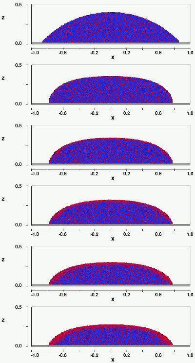
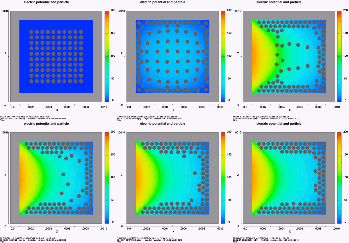
Dielectrophoresis (DEP)
DEP는 particle/fluid의 dielectric 특성이 주변 매체의 dielectric 특성과 다를 때만 발생한다.
Inputs required:

섬세한 경계를 가진 두 개의 유체, 표면 장력, electric potential, fluid electric charge, dielectrophoresis, newtonian viscosity
Electro osmosis
Micro-pump example

Inputs required:

Electro-thermal effects (Joules heating)

Magneto Hydrodynamics

Xiaozheng Xue1, Ioannis H. Karampelas1, Chenxu Liu2 and Edward P.
Furlani1,2
1 Department of Chemical and Biological Engineering
2 Department of Electrical Engineering
SUNY at Buffalo
FLOW-3D Americas User Conference , Toronto, 2014
Magneto Hydrodynamics

Use of magnetic field to align beads

John Wendelbo MEng, MSc.
Senior CFD Engineer, Flow Science
john.wendelbo@flow3d.com

 다양한 표면 장력을 사용하여 도장된 표면
마이크로 채널의 패턴 표면은 액체 사이의 실제 물리적 벽 없이 여러 액체가 나란히 흐르는 특정 경로를 따라 한 저장 장치에서 다른 저장 장치로 액체를 운반하는 데 사용될 수 있습니다. 패턴이 있는 표면은 액체를 lab-on-a-chip, 생물학적 경로, 마이크로 프로세서 및 화학적, 생물학적 감지 장치로 운반하는 데 사용됩니다.
이 경우 표면 장력은 미세 채널의 유체 흐름을 조작하여 패턴이 있는 흐름을 만드는 데 사용됩니다. 고체 표면에 있는 유체의 친수성 또는 소수성 거동은 마이크로 채널을 통해 복수 유체의 움직임을 제어하기 위해 이용됩니다.
마이크로 채널 내부의 유체 흐름은 층류로, 이는 다중 유체 흐름(이 경우 2개)이 난류 혼합 없이 나란히 흐를 수 있음을 의미합니다. 유체 스트림 측면에 물리적 벽이 없기 때문에 스트림은 이른바 가상 벽으로 제한됩니다. 이 벽들은 기본적으로 두 액체 사이의 친수성 경계입니다.

세가지 단계를 보여 주는 실험 결과 – A, B및 C(왼쪽에서 오른쪽으로), Bin Zhao et al.
위의 그림은 실험에서의 마이크로 채널을 보여준다. 중앙 수평 채널의 중간 스트립은 친수성인 반면, 상단 및 하단 수직 채널과 함께 남아 있는 채널은 친수성의 정도가 다릅니다. 그들은 단지 몇도의 접촉점 각도에 의해서만 그들의 친수성이 다릅니다. 상부 채널의 접점 각도는 118o 이고 하부 채널의 접점 각도는 112o입니다. 그러나 이러한 접촉 각도의 작은 차이는 유체가 이러한 영역으로 흐르기 위해 상당히 다른 압력을 필요로 합니다.
처음에는 모든 채널에 각기 다른 유체가 주입됩니다(투명). 분홍색 유체를 수평 채널로 밀어 넣으면 중앙 영역의 친수성 경로(PhaseA)를 따라 이동합니다. 압력이 증가함에 따라, 유체는 하부 친수성-친수성 장벽을 깨고 바닥 소수성 구역으로 흐르기 시작합니다(상 B). 압력이 더욱 증가하면 유체가 마침내 상부 친수성-친수성 장벽을 깨고 상부 영역에서도 흐르기 시작합니다(단계 C).

A, B, C의 세 단계를 보여주는 수치 결과입니다.
위의 수치해석 결과는 두가지 사이에 중요한 차이가 있다는 점을 고려할 때 실험에서 패턴이 있는 표면 연구의 전반적인 아이디어와 비교할 수 있는 합당한 수준을 보여줍니다. 위에 표시된 수치해석 결과는 과도 상태(압력이 지속적으로 증가함)이므로 유체 경계는 실험 결과와 정확히 동일하지 않습니다. 마찬가지로 유체 특성은 실험에 사용된 특성과 정확히 동일하지 않습니다.
그럼에도 불구하고 유체 1은 실험에서와 같이 압력이 증가함에 따라 A, B, C단계를 거칩니다. B단계에서는 투명한 유체가 상부 채널을 통해 계속 흐르지만, 하부 영역에서는 분홍색 유체만 흐릅니다. 이것은 실험과 일치합니다.
흥미로운 것은 C단계의 거품 형성입니다. C단계의 거품 형성과 같은 흥미로운 물리현상의 재현과 연구는 미세 유체학 장치의 설계와 제작 과정에 중요할 수 있습니다.
아래의 애니메이션은 위와 같은 실험에 대한 FLOW-3D 시뮬레이션 결과를 보여줍니다. 유체 1( 연한 파란 색)은 실험 중인 분홍색 유체와 같습니다. 처음에는 전체 영역이 Fluid2(투명 유체)로 채워집니다. 압력은 단계적으로 증가하며 시뮬레이션이 진행됨에 따라 세 단계를 모두 볼 수 있습니다.
Evolution of fluid flow with increasing pressure in patterned micro channels created by varying contact angles.
Ref: Bin Zhao, Jeffrey S. Moore, David J. Beebe, Surface-Directed Liquid Flow Inside Microchannels, Science 291, 1023 (2001)
Learn more about the power and versatility of modeling microfluidic applications with FLOW-3D

3D 댐 붕괴 문제 검증
이 기사는영국에서 Peter Arnold, Minerva Dynamics, The Guildhall, High Street Bath에 의해 기고되었다.
자유 표면 흐름 시뮬레이션을 위한 FLOW-3D 성능을 평가하기 위해, 장애물 구성이 포함된 3D댐을 검증 사례 중 하나로 선정했습니다. 이 문제는 문서화되어 있으며 ERCOFTAC데이터베이스에서 다운로드할 수 있도록 생성된 모든 실험 데이터를 사용하여 쉽게 설정할 수 있습니다[1]. 장애물은 선박 갑판의 녹색 물에 노출된 컨테이너를 대표하는 것으로 선택됩니다. 실험은 0.55 m의 물을 고정하는 슬라이딩 도어를 가진 대형 탱크 그림 1로 구성됩니다. 도어는 중량 감소에 의해 수직으로 위쪽으로 열리고 물이 방출되어 장애물을 침해한 후 탱크 벽으로부터 3회 반사됩니다. 자유 표면 고도는 탱크 중심선을 따라 4개 위치에서 측정되며 8개의 압력 센서가 장애물의 선행 수직 및 수평 표면에 내장되어 있습니다(그림2). FLOW-3D를 사용한 CFD시뮬레이션은 연속적으로 미세한 메쉬를 사용하여 6초간 실시간으로 수행되었으며 다른 주문 번호 체계와 난류 모델을 사용했습니다.

Figure 1. Snapshot of SPH simulation and experiment at 0.56 secs
시뮬레이션 방법론
시뮬레이션은 3.22mx1mx1.5m 크기의 도메인에 대해 설정되었습니다. 즉, 탱크 지붕에 대한 수직 분사를 허용하기 위해 z방향에서 0.5m 더 큰 도메인이 설정되었습니다. 기본 메쉬는 x-방향의 간격 161개, y-방향 50개, z-방향의 경우 75개가 균일하게 수용되는 육각 셀을 가지고 있었습니다. 장애물 및 센서 위치를 방해하므로 총 약 603,750개의 셀이 사용됩니다. 장애물은 그 영역에 들어갔고 모든 벽은 미끄러짐이 없는 것으로 간주되었습니다. 물의 초기 위치와 점도를 규정한 후, 층류 시간에 의존하는 시뮬레이션을 실시간으로 총 6초 동안 점진적으로 미세화하였습니다. 기본 60cm 셀 메시에서 시작하는 메쉬. 단순히 각 방향의 셀의 수를 2개의 큐브 루트에 의해 증가시킴으로써 각 점진적 메쉬에 대해 총 셀 카운트를 2배 증가시키는 것이었습니다. 이렇게 총 네개의 메쉬가 생겼습니다. 그런 다음 네개의 위치에서 자유 표면 고도의 시간 이력과 여덟개의 압력 센서로부터의 압력을 실험 데이터에 대해 도표로 작성했습니다. CPU와 시뮬레이션의 경과 시간또한 기록되었습니다.

Figure 2. Locations of water height and pressure measurements
기본 메쉬만 사용하여, 추진력 유도에 사용된 수치 구별 계획의 효과를 조사하였습니다. 디폴트가 1st order, 2nd order monotonicity preserving 그리고 3rd order schem이 모두 사용되었으며 결과를 비교했습니다. 또한 single 과 double precision의 효과를 비교하였습니다.
난류 변동은 주로 직접 시뮬레이션을 통해 모델링되었지만 FLOW-3D에서 사용할 수있는 두 가지 난류 모델, 즉 RNG (Renormalization Group) 모델과 LES (Large Eddy Simulations) 모델의 결과도 비교했습니다. 모든 모델은 가장 거칠고 기본 메쉬에서만 실행되었습니다. 메쉬 해상도에 대한 과도한 요구로 인해 탱크 벽에서 가장 가까운 노드의 거리에 대한 일반적인 난기류 모델 관련 제약 조건을 충족시키지 못했습니다.
또한 흐름이 크게 혼란스럽고 장애물이 날카로울 때 흐름 분리 효과의 예측은 점진적인 구분에 의해서가 아닌 기하학적 변화에 의해서 주도될 것입니다. 질서 정연한 경계 층의 변형 따라서, 우리는 경계 층의 분해능이 주 흐름 특성을 예측하는 관점에서 도메인 내부의 흐름을 해결하는 것보다 덜 관련된다고 가정했습니다.
자유 표면 결과
그림 3과 4는 장애물의 상류 위치 H2와 하류 위치 H1에서 시간에 대해 플롯 된 실험 및 계산 된 자유 표면 고도를 보여줍니다. 크기와 타이밍에 약간의 차이가 있지만 주요 기능이 잘 표현되어 있는지 확인하는 것이 좋습니다. 그러나 실험 데이터에는 오류 막대가 제공되지 않으며 혼란스럽고 분리 된 유동장에서 프로브를 사용하여 자유 표면 고도를 측정하는 것은 자유 표면 고도가 문제가 될 수 있다고 말해야합니다. 단일 한 시간 함수가 될 수 없습니다. 이것은 아마도 약 1 초의 초기 가파른 상승 단계에서 H1 높이의 불일치를 설명합니다. 나머지 H1 레코드는 실험과 잘 일치합니다. H2 플롯은 특히 초기 물 상승 단계에서 더 나은 일치를 보여주고 궁극적으로 물의 최대 높이를 잘 예측합니다.
모든 그림에는 실험 뒤에 있는 시뮬레이션의 시간 지연 특징이 있습니다. 차이의 원인은 불분명하지만 시뮬레이션을 통해 점진적으로 도입되는 것으로 보입니다.

압력 센서 결과
그림 5는 시간에 대해 플롯 된 바닥에서 가장 가까운 전면 압력 센서 P1을 보여 주며, 일반적으로 실험과 시뮬레이션 간의 양호한 일치를 나타냅니다. 이 센서는 압력 피크의 도달 거리와 크기를 가장 정확하게 추정합니다. 장애물과 왼쪽 벽에서 물이 튀어 나오면서 신호가 안정되면서 약 2초간 도달할 때까지 압력 신호에 상당한 변동이 있습니다. 그리고 시뮬레이션 값은 실험 값과 잘 일치합니다.

그림 6은 상부 수평 얼굴 압력 센서 P7을 보여 줍니다. 1초에서 2초 사이에 압력 변동이 크므로 시뮬레이션과 실험 데이터가 안정되고 합의가 개선됩니다.
메쉬 수리, 수치 구성 순서 및 난류 모델
메쉬 정밀도의 효과 측면에서 볼 때, 수치 솔루션이 고유한 솔루션으로 수렴되고 있다는 증거는 거의 없는 것으로 보입니다. 난류 모델을 사용하는 대신 직접 시뮬레이션을 통해 유동장의 난류를 모델링 하려고 시도해 왔기 때문에 이는 놀라운 일이 아닐 수 있습니다. 이 접근 방식을 사용하면 메쉬가 미세하게 정제되고 초기 조건에서 섭동에 더 민감해 지기 때문에 흐름 필드에서 보다 상세한 정보를 파악할 수 있을 것으로 예상됩니다. 또한 약간 다른 초기 조건을 가진 많은 시뮬레이션의 평균이 메시 정교함으로 평균화된 솔루션으로 수렴될 것으로 예상합니다. 그러나, 실험에 대한 합의의 수준에 있어서는 35배나 더 오래 걸리는 가장 적은 비용과 가장 비싼 해결책 사이에는 차이가 거의 없습니다. 공학적 관점에서 볼 때, 가장 불리한 메쉬 솔루션은 기본 값이 충분히 정확하고 경과된 시뮬레이션이 단지 15분 이상인 것을 고려할 때 매우 좋은 가치를 나타냅니다.
가속도계 숫자 체계 순서의 효과와 단일 또는 이중 정밀도 산술 실행의 효과는 다음과 같이 요약됩니다. 2차 주문과 3차 주문 계획은 매우 유사한 결과를 보여 주는데, 두가지 모두 실험 곡선을 따르는 것이 더 다양한 1차 주문 계획보다 더 가깝습니다. 또한 상위 순서 방식은 보다 정교한 메쉬의 첫번째 순서 방식보다 코어저 기본 메쉬의 실험 곡선을 따르는 것으로 보입니다. 이중 정밀도 곡선은 단일 정밀도 1차 주문 곡선에서 약간 벗어납니다. 높은 순서도와 이중 정밀도 산술을 사용하는 데 드는 상대적으로 적은 비용을 감안할 때 안정성이 훼손되지 않는다면 향후 계산에서 그렇게 하는 것이 합리적일 것입니다.
난류 변동을 모델링 하는 데 사용되는 방법에 대해서는 각 모델의 실험 시간 이력을 보다 정확하게 예측할 수 있는 능력 면에서 확실한 승자가 없습니다. LES모델의 CPU시간을 더 전통적인 RNG제제와 비교할 때 거의 두 배만큼 층류 모델로써 경제적입니다.
결론
FLOW-3D는 매우 까다로운 자유 표면 유동 문제를 시뮬레이션하는 데 사용되었으며 실험 데이터와 정 성적, 양적 계약을 맺었습니다. 주요 불일치는 종종 고유하지 않은 매개 변수의 자유 표면 높이를 측정하는 데 문제가 있기 때문에 쉽게 발생할 수 있습니다. 흐름이 충돌하는 장애물 표면의 압력 예측은 일반적으로 실험 측정과 잘 일치하며, 주 편차는 실험 측정에서 상당한 양의 변동이있는 곳에서 다시 나타납니다. 실험 측정의 반복성은 문헌에서 논의되지 않았지만 적어도 CFD 시뮬레이션의 차이만큼 클 수있다. 또한 4 개의 프로세서를 통한 공유 메모리 구성에서 약 15 분 내에 난류 모델없이 1 차 차분을 사용하여 비교적 거친 메시에서 솔루션을 적절하게 얻을 수 있음을 확인했습니다. 난류 모델이 필요하지 않다는 것은 결과 흐름을 지배하는 난류 구조가이 수준의 메쉬 미세 조정에서 해석 될 수 있음을 시사합니다.
Download a full-length validation study of this work: FLOW-3D Dam Breaking Validation
References

자기 혈액 정화 마이크로 장치의 최적화
이 기사는 스페인 칸타 브리아 대학 (University of Cantabria) 화학과 및 버팔로 (뉴욕), 미국 뉴욕 주립 대학 생화학공학과의 enifer Gómez-Pastora, Eugenio Bringas, Inmaculada Ortiza 및 Edward P. Furlanib에 의해 기고되었습니다.
자성 입자와 독소의 분리. 왜 그렇게 중요한가?
자성 입자의 사용은 최근 독성 물질의 혈류에서 다른 독소가 체외로 포획되는 해독 (disoxification) 과정으로 확대되었습니다. 생체 유체의 해독은 많은 수의 임상 상태에서 가장 생각할 수있는 치료법이며, 일부는 패혈증과 같은 높은 사망률과 관련이 있습니다. 이것은 혈류를 통해 퍼지면서 신체의 방어력을 압도하는 미생물 감염에 의한 치명적인 질병입니다. 이는 미국 내에서만 연간 1800 만 명의 사람들에게 고통을주고 매년 20 만 명이 넘는 사망을 초래하는 병원 중환자 실에서의 주요 사망 원인을 나타냅니다. 정확한 치료를 시행하기 전에 사망률이 매 시간마다 9 % 나 증가한다는 것을 볼수 있습니다. 따라서 최첨단 병원 중환자 실에서도 독소를 신속하게 제거하는 것이 가장 중요합니다.
우리는 현재 치료법의 한계가 독소 격리 제로서 자성 비드를 사용하는 것과 같은 새로운 전략의 개발을 필요로한다는 것을 발견했습니다. 입자의 자기 적 특성으로 인해 병원체의 포획이 완료되면 영구 자석에 의해 생성 된 외부 자기장을 사용하여 환자의 혈액과의 분리가 연속적으로 수행 될 수 있습니다. 지난 10 년 동안 개발 된 다중 자기 마이크로 세퍼레이터로부터 우리는 2 상 연속 흐름 시스템의 사용을 제안했습니다. 이러한 시스템은 흐름 제한 및 생체 유체의 임의의 분해 (즉, 포획 영역 내의 세포의 비특이적 포획)가 회피되어 시간 경과에 따른 시스템의 효능 및 용량을 유지하기 때문에 최선의 대안일 것입니다 [1]. 그러나 이러한 프로세스의 최적화는 덜 연구되었고 합리적 설계는 종종 수학적 설명과 관련된 복잡성으로 인해 부족합니다. 따라서 우리는 체외 해독 과정의 설계를 최적화하기 위해 FLOW-3D로 다중 위상 시스템 내부의 흐르는 혈류로부터 자기 구슬의 분리를 모델링했습니다. 그림1에 나타난 제안된 분리기 디자인에서, 비드는 상부 입구를 통해 연속적으로 주입되고, 자기 구배의 적용에 의해 편향되고 유동 버퍼 스트림으로 수집됩니다. 유체 위상의 혼합을 피하면서 효율적인 분리를 달성하기 위해, 자력 및 유체력을 신중하게 연구하고 최적화했습니다. 구슬이 편향 될 때 입자 – 유체 상호 작용에 대한 상세한 연구도 제공됩니다.
그림 1. 제안 된 microfluidic bioseparator의 도식 다이어그램 ([2]에서 채택).
첫번째로 보여지는 생체 분리기 내부의 자기 영동 입자 수송을 예측하기위한 모델은 CFD 기반의 오일러 – 라그랑지안 (Eulerian-Lagrangian) 접근법으로 구성됩니다. Navier-Stokes 방정식을 풀어서 예측 한 유체 이동은 오일러 접근법을 사용하여 계산되지만, 우리는 비드 역학을 모델링하기 위해 라그랑지안 프레임 워크를 사용했습니다. 라그랑지안 (Lagrangian) 접근법에 따르면 입자는 개별 단위로 모델링되었으며 각각의 궤도는 고전적인 뉴턴 역학을 적용하여 추정되었습니다. 분리 동안 입자에 작용하는 힘은 다르지만 영구 자석에 의해 생성 된 자기 구배 하에서 비드 궤적을 예측하기위한 지배적 인 자력 및 유동력만 고려했습니다. 유체의 동일한 유입 속도를 유지하면서 채널의 하부 벽과 자석의 상단 사이의 거리를 변화시킴으로써 다른 입자 궤적 및 따라서 분리 효능을 얻었습니다 (버퍼에 대해 0.035mS-1, m • s-1). 우리가 개발 한 모델링 노력에 대한 자세한 내용은 출판 된 연구 [1, 2]에서 찾을 수 있습니다.
그림 2. 자석과 마이크로 채널 사이의 거리 “d”를 변화시킴으로써 제공되는 서로 다른 자기장 하에서의 입자 궤적 (빨간색 선) ([2]에서 채택). 윤곽 플롯은 채널에서 예상되는 평균 유체 속도 크기를 나타냅니다.
입자 자기 영동 결과
자석의 위치를 변화시킴으로써, 우리는 가변 자장 구배가 발생하고, 따라서 상이한 분리 효율이 얻어짐을 입증했습니다. 그림 2는 자석과 채널 사이의 거리 d가 다른 입자의 궤도를 보여줍니다. 0 ~ 1mm 사이의 거리에서 모든 입자는 입구에서 원래 위치와 별개로 분리됩니다. 더 큰 거리의 경우, 낮은 자기력으로 인해 분리가 불완전합니다. 완전한 입자 분리를 위해서는 중 ~ 고 자력이 필요합니다. 그러나, 우리는 높은 자력이 유체 패턴의 섭동과 유체 계면의 파손으로 이끄는 입자의 극도의 가속으로 인해 해독 목적에 바람직하지 않음을 입증했습니다 (그림 3 참조). 따라서 중간 자력이 나타나게됩니다. 완전한 비드 분리가 혈액의 완전성을 유지하면서 달성 될 수 있기 때문에 이러한 종류의 시스템에 가장 적합할 수 있습니다.
그림 3. 입자가 a) d = 0 mm 및 b) d = 1.15 mm에 대해 상간 경계면을 횡단 할 때의 속도 벡터. c) d = 0 mm 및 b) d = 1.15 mm ([2]에서 채택)에 대한 그 당시의 혈액 체적 분율.
본 연구에서는 다중 위상 연속 흐름 마이크로 디바이스에서 혈액으로부터 자기 비드 분리 과정을 예측하고 최적화 하기위한 새로운 FLOW-3D 모델을 소개했습니다. 이 모델은 입자에 작용하는 우세한 힘을 고려하고 개별 입자의 궤도, 분리에 필요한 시간 및 혈액 / 버퍼 동시 흐름의 섭동을 포함하여 분리 과정의 중요한 세부 사항을 연구하는데 사용될 수 있습니다 . 이 연구의 핵심 요소는 유체 장에서 입자 – 유체 상호 작용의 영향을 고려하면서 장치에서 동시에 흐르는 두 유체 간의 상호 작용을 연구 한 것입니다. 솔루션이 채널의 길이를 따라 독립적으로 흐르고 각각의 출구에서 분리되어 가능한 혈액 손실이나 용해를 피하기 때문에 이러한 문제는 매우 중요합니다. 여기에 이어지는 방법론은 핵심 작동 변수 및 매개 변수를 고려하여 입자 분리를 예측하는 데 사용할 수 있으므로 합리적인 설계 지침을 제공합니다. 일반적으로 혈액 해독 과정뿐만 아니라 미세 유체 장치 내부에 여러 개의 구속 된 액체 상을 포함하는 다른 연구를위한 파라 메트릭 분석 및 최적화에도 적용됩니다. 우리의 미래 연구는 새로운 혈액 해독 과정을 설계하기 위해 전혈을 사용하는 과정의 실험적 분석과 자성 분리 단계의 독소 제거와 통합에 초점을 맞출 것입니다.
References
[1] Gómez-Pastora et al., Separation and Purification Technology, 2017, 172, 16–31.
[2] Gómez-Pastora et al., Journal of Physical Chemistry C, 2017, 121, 7466−7477.

FLOW-3D 해석 시 유체의 수면(자유 표면)의 위치를 데이터로 생성하는 방법
1. 아래와 같이 유체의 수면 형상이 있다고 가정.
2. Text output > fraction of fluid 선택 후 단면과 동일한 x, y, z 좌표 설정.
3. Render 후 text 파일로 저장.
4. Excel에 불러온 뒤 전체 data를 f 오름차순으로 정렬. 수면부는 0<f<1 이기 때문에 f=0, 1 값의 행을 모두 제거.
5. 0<f<1 임을 확인 후 다시 data를 z에 대해서 내림차순으로 정렬.
6. x의 위치와 fraction 값을 엑셀에 나타낸 수식으로 계산.

정밀 주조 공정은 가장 오래된 주조 공정 중 하나로 기원전 4000년 이후에 보편화되었습니다. 이 과정은 용해된 금속을 소모품(왁스)패턴으로 생성된 세라믹 쉘에 주입하는 과정을 수반합니다. 일찍이 그것은 금, 은, 구리와 청동 합금으로 장신구와 우상을 만드는데 사용되었습니다.
정밀 주조공정은 1897년 아이오와 주, 위원회 블러프스의 Barabas Frederick Philbrook이 묘사한 대로 치과의사들이 왕관과 인레이를 만들기 위해 그것을 사용하기 시작한 19세기 말 현대 산업공정으로 사용되기 시작했습니다. 1940년대에는 제2차 세계대전 당시 기존 방법으로는 형성될 수 없거나 지나치게 많은 가공이 필요한 특수 합금의 정밀 순모형 제조 기술에 대한 수요로 인해 투자 주조 공정이 증가하였습니다.
오늘날 정밀 주조 공정은 표면 마감 및 치수 정확도가 우수하여 거의 순 형태에 가까운 철, 비철 및 초합금의 소형 산업용 부품을 생산하는데 주로 사용됩니다.
정밀 주조 공정은 다음 네 가지 주요 단계로 구성됩니다.

Figure 1. Solid model of the casting geometry
정밀 주조 공정에서 얻은 부품은 많은 중요한 용도에 사용되므로 내부적인 결함이 없어야 합니다. 정밀 주조 공정에서 발생하는 주요 결함은 세라믹 포함, 균열, 변형, 플래시, 주탕불량, 수축, 슬래그 포함, 탕경계등입니다. 얻은 주조물의 품질을 예측하려면 금속-몰드 열 전달계수, 주입 온도 등 다양한 주조 공정 매개 변수의 영향을 연구해야 합니다. 즉, 쉘 두께 및 쉘 열 전달계수가 그것입니다. 현대 컴퓨터 시스템 및 시뮬레이션 소프트웨어의 출현과 함께 금형 충진 및 응고 시뮬레이션은 주조공장에서 결함을 예측하고 설계를 최적화하는데 점점 더 많이 사용되고 있습니다.
이 연구의 주요 목적은 정밀 주조 공정에서 주요 요소인 복사 열 전달과 정밀 주조 공정에 고유한 쉘 금형이 FLOW-3D에서 효과적으로 구현될 수 있는지를 조사하는 것입니다. FLOW-3D를 사용하여 간단한 형상을 위한 정밀 주조공정의 주입 및 응고 시뮬레이션을 수행함으로써 두 구성요소의 서로 다른 효과를 조사합니다. 다양한 위치에서 얻은 온도의 수치는 문헌 [1]에보고 된 실험 결과로 검증됩니다. 복사 열 전달계수, 쉘 몰드 두께, 탕구 및 게이트의 위치에 대한 영향도 조사했습니다.
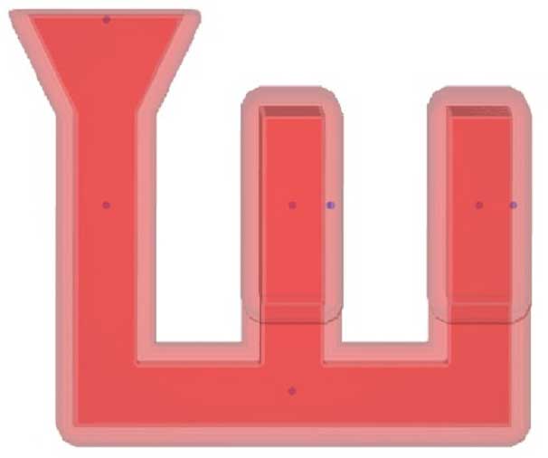
Figure 2. Shell mold
현재 연구에서 사용된 계산 형상은 그림 1에 나와 있습니다. 쉘 몰드는 다음 단계를 사용하여 작성되었습니다.
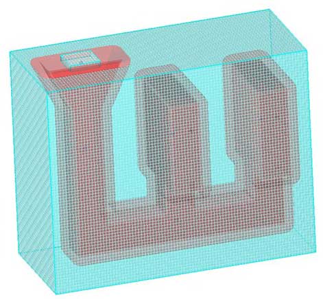
Figure 3. The view of the two mesh blocks for the creation of a void with discretization
쉘 몰드 용 STL 파일을 만든 후에, 이 파일을 component 1로 새 시뮬레이션으로 가져오고 이전에 작성한 주조 형상을 하위 구성 요소로 가져오고 유형을 ‘hole’으로 선택합니다. 쉘 몰드와 함께 주조 형상이 그림 2에 나와 있습니다. 이것은 우리의 계산 영역으로 사용됩니다. 다음은 계산 영역을 cubical/rectangular셀로 분할하기 위한 메쉬를 만드는 것입니다. 메쉬 블록을 작성하여 FLOW-3D에서 메쉬를 생성합니다. 현재의 작업을 위해 2.5mm의 고정된 셀 크기가 선택된 그림 3에 표시된 균일한 메쉬 옵션을 선택했습니다. 입력 위치 주변에 메시 블록 2가 사용되는 현재 시뮬레이션을 위해 메시 블록 2개가 생성되었습니다. 쉘과 주변 공기 사이의 30°C에서의 열 전달을 고려하여 쉘 주위에 보이드 영역이 정의됩니다. 이 영역은 ‘heat transfer type 1’이 있는 보이드 영역으로 선택되며 셸과 주변 공기 사이에 열 전달 계수 값이 지정됩니다. heat transfer type 1은 방사선을 포함한 종합 열 전달 계수가 됩니다.
쉘 주형에 선택된 재료는 zircon이며 열 특성은 Sabau and Vishwanathan에 의해 수행된 실험에서 얻을 수 있습니다[2]. 표 1은 연구에 사용된 재료에 대해 지정된 값을 보여 줍니다.
| MATERIAL | PROPERTY | VALUE | UNIT |
| Fluid –AluminiumA356 alloy | Density | 2437 | kg/m³ |
| Thermal conductivity | 116.8 | W/(m K) | |
| Specific heat | 1074 | J/(kg K) | |
| Latent heat | 433.22 | kJ/m³ | |
| Liquidus temperature | 608 | 0C | |
| Solidus temperature | 552.4 | 0C | |
| Zircon Mold | Thermal conductivity | 1.09 | W/(m K) |
| Specific heat* Density | 1.63E+06 | J/( m³ |
Initial and boundary conditions used are show in Table 2.
| Mold temperature | 430°C |
| Melt pouring temperature | 680°C |
| Filling time | 7 s |
| Interface heat transfer coefficient | 850 W/m2K |
| Heat transfer coefficient between ambient and mold (radiation effect) | 30 -100 W/m2K |
Table 2. Initial and boundary conditions used for the simulation
Sprue basin에 들어가는 용융물의 초기 속도와 온도는 메시 블록 2의 상단 경계에서 속도 경계 조건으로 주어집니다. 기본적으로 다른 모든 경계는 대칭 유형으로 설정됩니다.
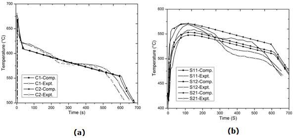
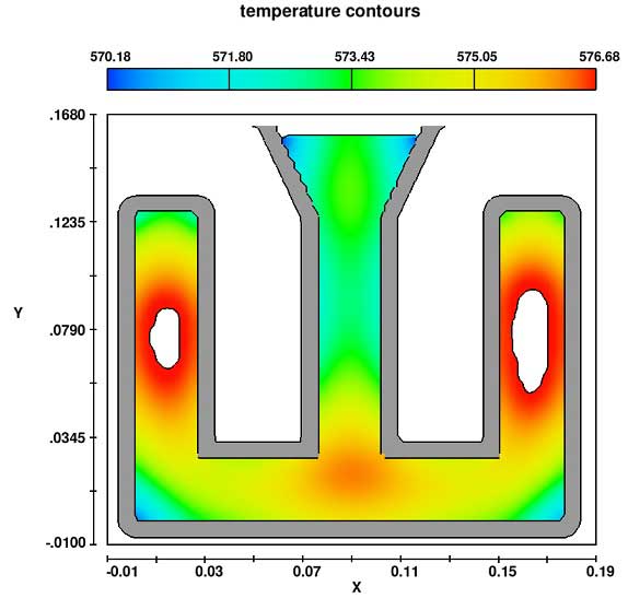
충전 및 응고 동안 냉각 곡선을 얻기 위한 실험에서 Sabuet.al[1]에 의해 선택된 네 개의 위치가 검증 목적으로 사용되었습니다. 그들은 C1, C2, S11, S12및 S21로 언급됩니다. C1과 C2지점은 주물의 플레이트의 중심에 있으며 S11, S12및 S21은 모두 쉘에 위치합니다. 이러한 위치에서의 온도 변화는 그림 4와 같습니다.
온도 프로파일의 수치 및 실험결과의 차이가 허용한계 안에 있음을 알 수 있습니다. probe points C1과 C2의 경우, 수치와 실험 결과 사이의 차이는 응고 중에 5%, 응고 후 냉각 시 12% 이내입니다. 쉘의 점에 대한 수치 결과는 실험 결과보다 약 5% 높습니다. 이는 쉘 재료에 열 물리학적 특성을 할당할 때 발생하는 가정과 쉘 열 전달 계수의 값 때문일 수 있습니다.
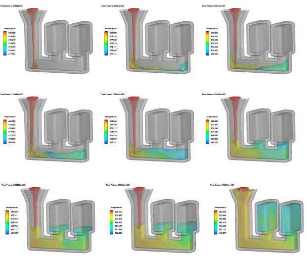
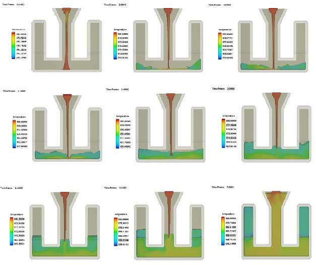
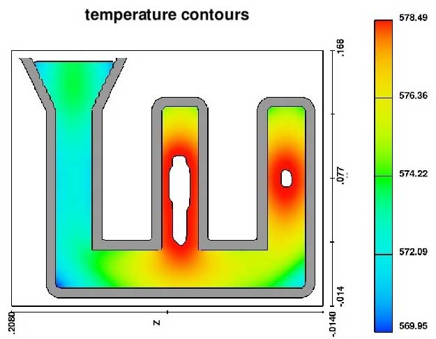
2 개의 상이한 탕구 위치에서 용탕 충전 순서는 5a 및 5b에 나와 있습니다. 최종 탕구가 더 많은 splashing을 생성하므로 결함으로 이어질 수 있습니다. 탕구가 중간에 놓여지면 흐름은 보다 균일 해지고 두 주조 단면에서 비슷한 온도 분포를 보입니다. 50 % 응고 후의 온도 프로파일의 2D 도면은 두 경우 모두 그림 5c 및 5d에 나와 있습니다. 수축 위치에서 볼 때 두 탕구 위치가 결함을 일으키는 것은 분명합니다.
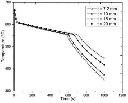
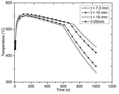
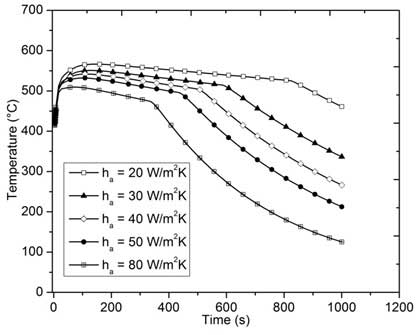
정밀 주조에 대한 쉘 두께의 효과를 연구하기 위해 두께가 7.2, 10, 15 및 20 mm인 주물을 선정하였습니다. 그림 6a 및 6b는 주조품의 특정 위치에서 냉각 곡선을 나타내며, 이는 C1으로 나타내고 쉘 몰드 내의 특정 위치에 있으며, 응고 중에 S11로 나타납니다. 세라믹 쉘의 두께가 7.2 mm에서 15 mm로 증가하면 냉각 속도가 감소하여 응고 시간이 길어지는 것을 볼 수 있습니다.
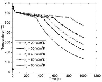
쉘 열 전달 계수는 열이 쉘 몰드의 외부 벽에서 방사선을 통해 주변 공기로 열을 방출하는 속도를 나타냅니다. 이 효과를 조사하기 위해 열 전달 계수의 값을 20에서 80W/m2K까지 다양하게 했습니다. 7a 및 7b로부터, h의 변화는 주조 재료 및 쉘의 냉각 속도에 중요한 영향을 미친다는 것을 알 수 있습니다. 열 전달 계수가 20에서 80W/m2K로 증가하면 C1에서의 응고 시간이 812 초에서 334 초 (약 44 %)로 감소되었음을 알 수 있습니다. 따라서, h의 값을 변화시키는 것은 주물의 미세 구조에 영향을 미칩니다.
정밀 주조 공정의 몰드 충진 및 응고 시뮬레이션은 FLOW-3D를 사용하여 수행되었습니다. 주조 공정에 대한 주조 매개변수의 영향을 연구하기 위해 파라메트릭 연구가 수행되었습니다. 본 연구에서 다음과 같은 결론을 도출 할 수 있습니다.
Sabau, A.S., Numerical Simulation of the Investment Casting Process, Transactions of the American Foundry Society, vol. 113, Paper No. 05-160, 2005.
Sabau, A.S., and Viswanathan, S., Thermophysical Properties of Zircon and Fused Silica-based Shells used in the Investment Casting Process, Transactions of the American Foundry Society, vol. 112, Paper No. 04-081, 2004.

레이저 파우더 베드 퓨전 (L-PBF) 첨가제 제조에는 복잡한 물리적 공정이 필요합니다. 특히, 흡수 된 레이저 빔 에너지는 입자를 녹여 강한 유체 흐름이 표면 장력 기울기 (또는 Marangoni 전단 응력)에 의해 주로 발생하는 용융 풀을 형성합니다. 열 전달 및 유체 유동은 분말 베드 내의 분말 입자의 국부적 배열에 의해 영향을 받으며, 이는 위치에 따라 다를 수 있습니다. 매우 일시적인 유체 흐름으로 인해 용융 된 풀 표면 (자유 표면)의 형상이 끊임없이 진화하여 최종 표면 품질에 영향을 미칩니다.
본 연구에서는 분말 포장 특성, 공정 변수 및 용융 풀 역학이 표면 품질에 미치는 영향을 정량적으로 이해하기 위해 두 가지 모델을 순서대로 사용합니다. 첫 번째 모델은 오픈 소스 이산 요소 방법 (DEM) 코드 인 Yade를 기반으로 개발 된 분말 입자 포장 모델입니다. 입자 적층 정보 (예를 들어, 개별 입자의 위치 및 반경)를 제공한다. 이러한 정보는 FLOW-3D를 기반으로 한 3D 과도 용융 풀 모델 인 두 번째 모델에 입력됩니다. 두 모델의 세부 사항은 문헌 [1]에 나와있다. FLOW-3D를 기반으로 한 용융 풀 모델의 특징을 요약하면 다음과 같습니다.
과도 유체 흐름 시뮬레이션은 그림 1에서와 같이 1000 μm (길이), 270 μm (너비) 및 190 μm (높이) 치수의 3D 계산 영역에서 수행됩니다. 도메인은 50 μm 두께의 층 의 분말 입자를 90㎛ 두께의 기판 위에 놓았다. 도메인의 미리 알림은 처음에는 무효로 채워집니다. 분말 층 형상은 DEM 시뮬레이션의 결과를 사용하여 초기화됩니다. 총 셀 수를 줄이면서 공간 분해능을 극대화하기 위해 메쉬 크기가 기판 / 파우더 레이어 인터페이스를 향하여 기판에서 9 μm에서 3 μm까지 연속적으로 감소하는 편향 메쉬가 사용됩니다. 메쉬 크기는 파우더 레이어와 그 위의 빈 공간에서 3 μm로 일정하게 유지됩니다. 총 셀 수는 143 만입니다.
경계 조건의 경우, 가우시안 분포에 기초한 소정의 열유속이 분말 층의 상부 표면에 부과되어 X 방향을 따라 이동하는 레이저로부터의 열 입력을 나타낸다. 온도에 따른 표면 장력은 FLOW-3D에서 사용 가능한 개선 된 표면 장력 모델을 사용하여 포함됩니다. 다른 열 – 물리적 특성의 경우, FLOW-3D 데이터베이스에서 사용 가능한 IN718 합금에 대한 데이터가 사용됩니다.
그림 2는 시간 = 55 μs에서 용융 풀 내의 온도 등면 및 속도 벡터의 종단면도 (즉, 레이저 이동 방향에 평행 한 단면)를 도시한다. 용융 된 풀 경계는 1608.15 K에서 등온선으로 표시되며, IN718의 액상 선 온도입니다. 이 그림의 오른쪽에 표시된 것처럼 입자는 부분적으로 용융 풀로 용융됩니다. 용융 된 풀 표면 근처에서, 용융 금속은 레이저 빔 바로 밑의 중심 위치에서 풀의 후단으로 당겨진다. 풀 표면 근처의 용융 금속의 이와 같은 역류는 풀의 후단을 향해 고비를 형성하는 동안 레이저 빔 아래에서 움푹 들어간 표면 프로파일을 생성한다. 다음에서 논의되는 바와 같이, 혹 모양은 볼 결함의 형성을 초래할 수 있습니다.

볼링(balling)은 그림 3에서와 같이 용융 풀이 불연속으로 분리되어 분리 된 섬으로 갈라질 때 발생할 수있는 결함입니다.이 그림에서 알 수 있듯이 레이저 빔 바로 아래의 용융 풀은 안정적이지 않으며 후단이 빠르게 분리됩니다 정면에서 분리 된 섬을 형성합니다. 분리는 그림 3 (c)와 같이 용융 풀의 중간에있는 보이드에서 시작된다. 이 공극은 레이저가 앞으로 계속 이동하면서 팽창하여 결국 용융 된 풀을 두 부분으로 나눕니다. 도 3 (e) 및 (f). 공극의 형성과 그 팽창은 표면 장력 구배 (Marangoni 효과)에 의해 강한 후진 유동에 의해 유발됩니다.

L-PBF에서의 열 전달 및 유체 흐름의 3D 과도 시뮬레이션은 볼 결함의 형성을 정량적으로 이해하기 위해 수행됩니다. 단순한 선형 트랙 만 시뮬레이션되었지만, 본 모델은 최종 빌드 품질의 중요한 속성 인 용융 풀 표면 프로파일 및 볼링 결함 형성을 연구 할 때 분말 레벨 시뮬레이션의 중요성을 보여줍니다.
뿐만 아니라 위의 금속 분말 소결 시뮬레이션은 금속 3D 프린팅(Metal 3D Printing) 산업의 핵심 기술이며 차후 많은 연구와 응용이 기대되는 분야가 될 것입니다.
이 자료는 수상 번호 N00014-14-1-0688하에 미해군 연구소(ONR)가 지원하는 연구과제에 기초로 작성되었습니다.
[1] Y.S. Lee and W. Zhang, Mesoscopic Simulation of Heat Transfer and Fluid Flow in Laser Powder Bed Additive Manufacturing, In: 2015 Annual International Solid Freeform Fabrication Symposium, Austin, TX, pp. 1154-1165, August 2015.

Advances in Nanotechnology
This article was contributed by Prof. Edward Furlani and his students from the University at Buffalo, SUNY.
Microfluidics와 nanofluidics는 나노와 나노사이의 기능을 가진 재료와 시스템을 통한 유체 흐름의 과학과 기술을 포함하는 분야입니다. 최근 몇 년 사이에 이 분야의 연구는 재료 개발과 시스템의 급속한 발전된 유체공정의 독특한 이점으로 증가해 왔습니다. Microfluidic 및 nanofluidic 시스템은 화학 반응, 유체 가열, 혼합 및 감지와 같은 순차적 또는 다중화된 공정을 포함할 수 있는 응용 분야에서 마이크로 사이즈의 유체 유동은 매우 효율적이고 반복 가능하며 신속한 처리를 가능하게 합니다. 풀 라니 (Furlani) 교수 그룹의 연구는 새로운 공정 및 장치 개발에 대한 모델링 및 시뮬레이션을 보여줍니다. 이 연구의 대부분은 뉴턴 및 비 뉴턴 유체, 열 전달, 상변화 분석, 자유표면 및 다상분석, 유체와 관련된 유체 현상을 연구하기 위해 최첨단 전산 유체역학을 강조합니다. 매체 상호작용, 다공성 매체를 통한 유동, 완전히 결합된 유체구조 및 입자, 유체 상호작용에 대해 콜로이드. 국제 나노 기술 학술 대회에서 3 편의 논문이 발표될 예정입니다. 2014년 6월 15일부터 18 일까지 워싱턴 DC의 Gaylord National Hotel 및 Convention Center에서 개최됩니다. 이들은 버팔로 대학교 (University at Buffalo)에서 진행되는 획기적인 결과를 선보입니다. 여기에서는 이러한 작품의 미리 보기와 FLOW-3D로 생성된 시뮬레이션 결과 중 일부를 제시합니다.
Analysis of Stem Cell Culture Performance in a Microcarrier Bioreactor System
Koushik Ponnuru1, Jincheng Wu1, Preeti Ashok1, Emmanuel S. Tzanakakis1,3,4,5,6 and Edward P. Furlani1,2
1Dept. of Chemical and Biological Engineering, 2 Dept. of Electrical Engineering, 3Dept. of Biomedical Engineering, 4New York State Center of Excellence in Bioinformatics and Life Sciences, 5Western New York Stem Cell Culture and Analysis Center, 6Genetics, Genomics and Bioinformatics, University at Buffalo, SUNY

(left) Shear stress distribution along with velocity vectors in a cross sectional plane of the bioreactor running at 60 rpm; (right) Kolmogorov length scale distribution at the same plane under the same conditions.
CFD 기반 시뮬레이션과 실험결과의 조합으로 교반 탱크의 마이크로 캐리어 생물 반응기 시스템에서 세포 배양에 대한 난류 전단응력의 영향에 대한 분석을 제시합니다. Corning’s bench-scale spinner flask의 3D 계산 모델은 최첨단 CFD 소프트웨어 인 FLOW-3D를 사용하여 제작되었습니다. 임펠러 속도, 배양액 및 입자 크기와 같은 매개변수가 마이크로 캐리어 입자에 작용되는 전단응력에 미치는 영향을 CFD 분석을 사용하여 연구하였습니다. 이것은 세포가 겪는 정확한 전단 조건을 예측하고 세포의 손상을 방지하는 최적의 작동조건을 확인하는데 사용됩니다. 또한, 다원능 마커 Oct4, Sox2 및 Nanog를 운반하는 세포의 비율을 세포 계측법 및 정량적 PCR을 사용하여 측정함으로써 hPSCs의 다능성 전단효과를 연구합니다.
Numerical Analysis of Fully-Coupled Particle-Fluid Transport and Free-Flow Magnetophoretic Sorting in Microfluidic Systems
Chenxu Liu1, Xiaozheng Xue1 and Edward P. Furlani 1,2
1Dept. of Chemical and Biological Engineering, 2Dept. of Electrical Engineering, University at Buffalo, SUNY

Magnetic nanoparticle chaining and rotating following an external field and causing the mixing of two different molecular concentrations.
Magnetic 입자는 생체 의학 및 임상 진단 응용을 위해 생체 재료를 선택적으로 분리 및 분류하는 마이크로 유체시스템에 점점 더 많이 사용되고 있습니다. 그러한 시스템의 합리적인 설계에 사용될 수 있는 전산모델이 도입되었습니다. 이 모델은 자기 및 유체 역학적 힘, 완전 결합 입자 – 유체 상호 작용 및 입자의 자기 조립을 유도하는 자기 쌍극자와 쌍극자의 상호 작용을 비롯한 입자 수송에 대한 지배적 메커니즘을 고려합니다. 응용 프로그램을 통해 연속흐름 분리시스템 및 회전 조립 체인을 기반으로 하는 미세 유체 혼합프로세스로 시연됩니다.
Numerical Analysis of Laser Induced Photothermal Effects using Colloidal Plasmonic Nanostructures
Ioannis H. Karampelas1, Young Hwa Kim2 and Edward P. Furlani 1,2
1Dept. of Chemical and Biological Engineering, 2 Dept. of Electrical Engineering, University at Buffalo, SUNY

Photothermal heat cycle of a nanocage (a=50nm, t=5nm) (perspective 1/8 view): plot of nanocage temperature vs. time, pulse duration indicated by the red arrow and dashed line and inset plots showing various phases of the thermo -fluidic cycle: (a) nanobubble formation, (b) nanobubble (maximum size), (c) nanobubble collapse, (d) cooling.
Colloidal 귀금속 (plasmonic) 나노 구조는 나노 입자 합성에서부터 바이오 이미징 (bioimaging), 의학 요법 (medical therapy)에 이르기까지 다양한 광열 (photothermal) 분야에서 점점 더 많이 사용되고 있습니다. 많은 응용분야에서, 펄스 레이저는 plasmonic 공진 주파수에서 나노 구조를 사용하며, 이는 광자의 흡수 및 고도로 국부화된 파장필드의 향상을 가져옵니다. 원격 소스로부터 효율적인 나노 스케일 가열하는 것 외에도, 합성동안 나노 입자의 구조를 조정함으로써 근적외선 스펙트럼을 통한 공진 가열파장을 조정할 수 있습니다. 우리 그룹은 nanosecond-pulsed, laser-heated colloidal metallic nanoparticles 및 열 유체 거동을 예측하는 전산모델을 개발했습니다. 이 모델은 플라즈몬 공명, 입자에서 주변 유체로의 열 전달 및 균일한 기포 핵 형성을 유도하는 유체의 위상변화에서 나노 입자 내의 에너지 전환을 시뮬레이션 하는데 사용되었습니다. nanorods, nanotori, nanorings 및 nanocages 등 다양한 nanoparticle 형상이 연구되었습니다. 이 분석은 레이저 강도, 입사 파장, 편광, 펄스 지속 시간 및 나노 입자의 방향 및 모양과 같은 공정 매개 변수가 광열 공정을 최적화하도록 조정될 수 있음을 보여줍니다. Plasmonic nanoparticles는 악성 조직의 약물 치료, 약물 전달 및 생체치료에 사용됩니다.

FLOW-3D의 신규 모듈 개발을 하면서, 입자 모델의 새로운 입자 부류 중 하나인 유체 입자의 기능에 초점을 맞출 것입니다. 유체 입자는 증발 및 응고를 포함하여 유체 속성을 본질적으로 부여합니다. 유체 입자가 비교적 간단한 강우 모델링에서 복잡한 레이저 증착(용접) 모델링에 이르기까지 다양한 사례가 있을 수 있습니다.
FLOW-3D에서 유체 입자 옵션이 활성화 되면 사용자는 다양한 직경과 밀도의 다양한 유체 입자 종을 설정할 수 있습니다. 또한 유체 입자의 동력학은 확산 계수, 항력 계수, 난류 슈미트 수, 반발 계수 및 응고 된 반발 계수와 같은 특성에 의해 제어 될 수 있습니다. 유체 입자는 열적 및 전기적 특성을 부여 받을 수도 있습니다.
사용자는 유체 입자 생성을 위해 여러 소스를 설정할 수 있습니다. 각 소스는 이전에 정의 된 모든 유체 입자 종 또는 일부 유체 입자 종의 혼합을 가질 수 있습니다. 또한 사용자는 무작위 또는 균일 한 파티클 생성을 선택하고 파티클이 소스에서 추출되는 속도를 정의 할 수 있습니다.
레이저 금속 증착은 함께 미세한 금속 분말을 융합하여 입체 금속 부품을 제작하는 3D printing 공정이다. 레이저 금속 증착는 항공 우주 및 의료 정형 외과 분야에서 다양한 응용 프로그램을 찾습니다. 레이저 금속 증착의 개략도는 아래와 같습니다. 전력 밀도 분포, 기판의 이동 속도, 차폐 가스 압력 및 용융 / 응고, 상 변화 및 열전달과 같은 물리적 제어와 같은 제어 매개 변수가 함께 작동하여 레이저 금속 증착을 효과적인 첨가제 제조 공정으로 만듭니다.
새로운 유체 입자 모델은 분말 강도 분포를 할당하고 용융 풀 주변에서 발생하는 복잡한 입자 – 기판 상호 작용을 포착하기 때문에 레이저 금속 증착 시뮬레이션을 설정하는 데 없어서는 안될 부분입니다.
일반의 사용자들은 FLOW-3D에서 시뮬레이션을 쉽게 설정할 수 있다는 점을 계속 알고 있을 것입니다. 레이저 금속 증착 설정의 경우에도 다른 점은 없습니다. IN-718의 물리적 특성, 형상 생성, 입자 분말 강도 분포, 메쉬 생성 및 시뮬레이션 실행과 같은 모든 설정 단계는 직접적이고 사용자 친화적입니다.

IN-718의 물성은 기판과 응고 된 유체 입자 모두에 사용됩니다. 40 미크론 유체 입자가 무작위 방식으로 초당 500,000의 속도로 입자 영역에서 계산 영역으로 주입됩니다. 입자 빔은 기판의 운동 방향이 변화 될 때마다 순간적으로 정지되어 용융 풀이 급격한 속도 변화에 적응하도록 합니다. 이렇게 하면 기판에서 입자가 반사되는 것을 방지 할 수 있습니다. 매 5 초마다 기판이 회전하기 때문에 입자 생성 속도는 아래 그림과 같이 5 초마다 0으로 떨어집니다. 기판 이동 자체는 표 형식의 속도 데이터를 사용하여 FLOW-3D에 지정됩니다. 입자는 응고 된 유체 입자로 주입되어 고온의 용융 풀에 부딪혀 녹아 용융 풀 유체의 일부가 됩니다.


Substrate velocity
입자 모델 외에도 FLOW-3D의 밀도 평가, 열 전달, 표면 장력, 응고 및 점도 모델이 사용됩니다. 보다 구체적으로, 온도에 따른 표면 장력은 증착 된 층의 형태에 큰 영향을주는 Marangoni 효과를 일으킵니다.
레이저를 복제하기 위해 100 % 다공성 구성 요소가있는 매우 기본적인 설정이 열원으로 사용됩니다. 100 % 다공성은 구성 요소 주변의 유동 역학에 영향을 미치지 않습니다. 오히려 그것은 특정 영역의 기판에 열을 효과적으로 부가한다. 이 예비 가열 메커니즘을 자회사인 Flow Science Japan이 개발 한 고급 레이저 모듈로 교체하는 작업이 현재 본격적으로 진행 중입니다. 가열 다공성 구성 요소는 각각의 층이 동일한 양의 열을 얻도록 각 층이 증착 된 후에 약간 위로 이동됩니다.
아래 애니메이션은 다중 층 증착을 이용한 레이저 금속 증착 공정을 보여줍니다. 기판이 방향을 바꿀 때마다 입자 빔 동작의 일시적인 정지를 확인하십시오. 또한, 층이 증착됨에 따라, 새로운 층의 형상은 다공성 열원으로부터 각 층에 열의 불균등 한 첨가로 인해 변화됩니다. 각 층을 증착 한 후에 열원을 위로 이동해야 하는 양을 측정하는 것은 현재의 기능에서는 어렵습니다. 다만 준비중인 Flow Science Japan의 레이저 모듈은 이 문제를 해결할 수 있습니다.
전반적으로 입자 모델은 레이저 금속 증착에서 매우 중요한 공정 매개 변수 인 분말 강도 분포를 정확하게 재현합니다. 입자 모델과 같은 수준의 제어와 정교함은 첨가제 제조 분야의 사용자와 공급자 모두가 제조 프로세스를 미세 조정하는 데 도움이 될 것으로 기대합니다.
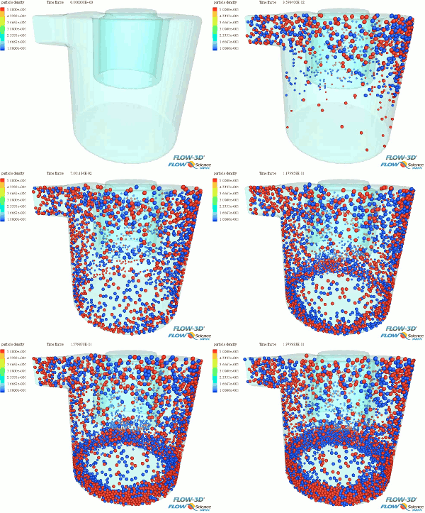
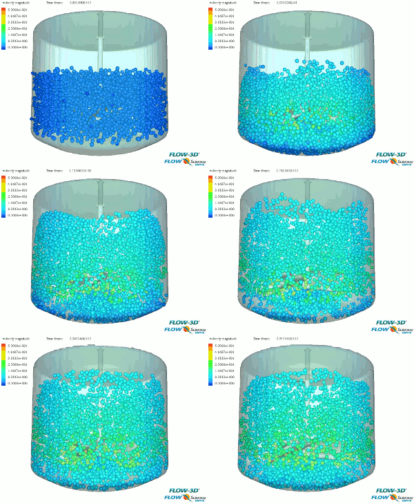
FLOW DEM 은 FLOW-3D 의 기체 및 액체 유동 해석에 DEM(Discrete Element Method : 개별 요소법) 기법인 입자의 거동을 분석해주는 제품입니다.
입자 – 입자 간, 입자 – 벽 사이의 접촉이나 상호 작용을 모델링 할 수 있으므로 보다 현실적인 입자 거동의 해석이 가능합니다.
또한 유체 부분은 전문적인 FLOW-3D 분석 기능을 사용하기 때문에 유체 와 입자거동의 연성해석을 정밀하게 또한 효율적으로 분석할 수 있습니다.
| 주요 기능 : |
|
다수의 고체 요소의 충돌 운동을 분석하는 데 유용합니다. 유동 해석과 함께 사용하면 광범위한 용도에 응용을 할 수 있습니다.
 |
 |
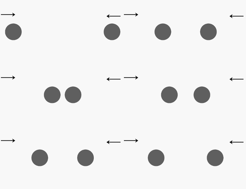
Voigt model은 스프링(Spring) 및 대시 포트(Dash pot)의 조합에 의해 입자 충돌 시의 힘을 평가합니다. 탄성력 부분은 스프링 모델에서,
비탄성 충돌의 에너지 소산부분은 대시 포트 모델에서 시뮬레이션되고 있으며, 중량 및 항력은 작용하는 외력으로 고려 될 수 있습니다.

|
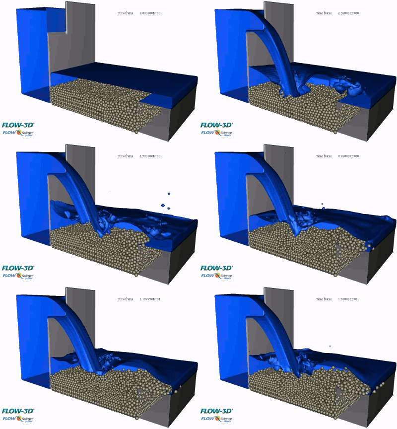
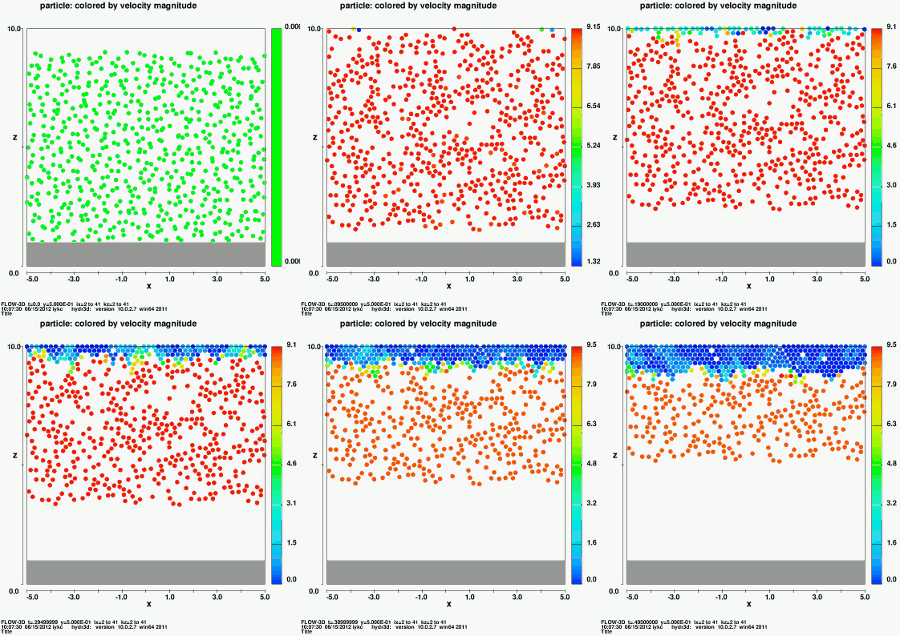
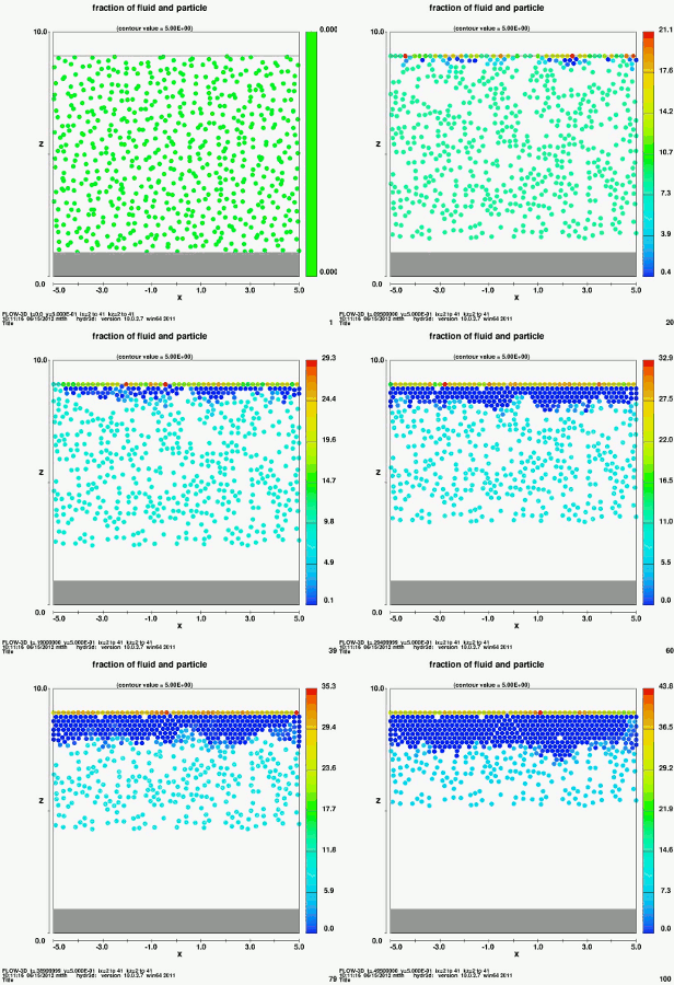
기본적으로 이용하는 운동 방정식은 FLOW-3D 에 사용되는 질량 입자의 운동 방정식과 같은 것이지만, 여기에 DEM으로 평가되는 항목이 추가되는 형태로 되어 있으며, 실제 시뮬레이션으로는 ‘void + DEM’, ‘1 Fluid + DEM’ , ‘ 1 Fluid 자유계면 + DEM ‘을 기본 유동 모드로 취급이 가능합니다.
 |
 |
 |
| void + DEM | 1-fluid + DEM | 1-fluid 자유계면 + DEM |
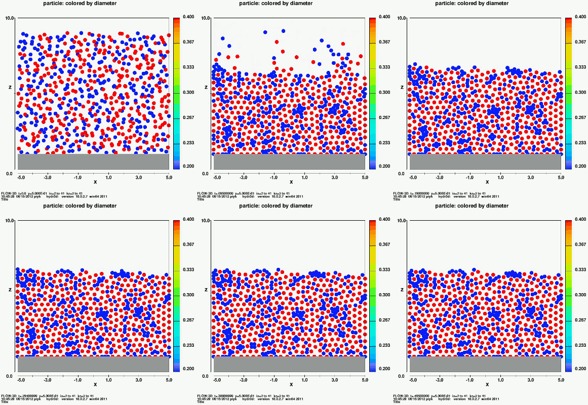
입자 타입도 표준 기능의 질량 입자 모델처럼 입자 크기 (반경)와 밀도가 동일한 것 외, 크기는 같지만 밀도가 다른 것이나 밀도는 같지만 크기가 다른 것 등도 취급 가능합니다. 이로 인해 표준 질량 입자 모델에서는 입자 간의 상호 작용이 고려되어 있지 않기 때문에 모든 아래에 가라 앉아 버리고 있었지만, FLOW DEM을 이용하여 기하학적 관계를 평가하는 것이 가능합니다.
 -균일 -균일-밀도 변화 -입자크기 변화 |
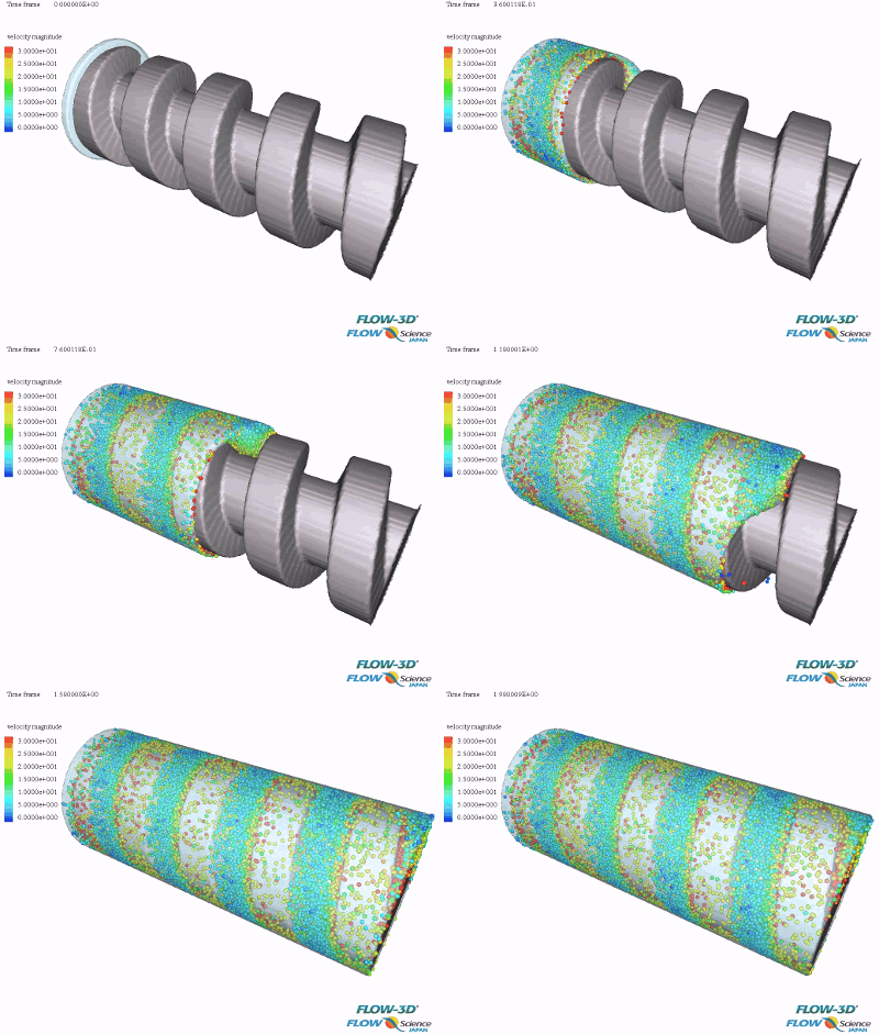
Resin filling, screw conveyance, powder conveyance
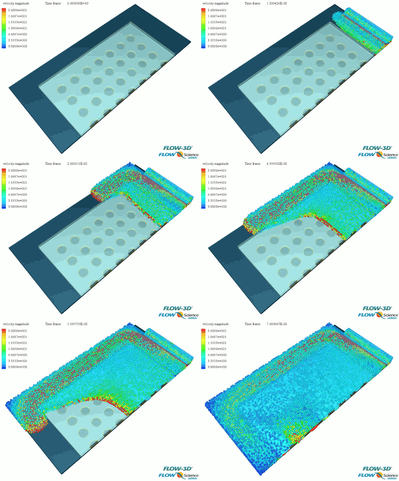 |
 |
 |
|
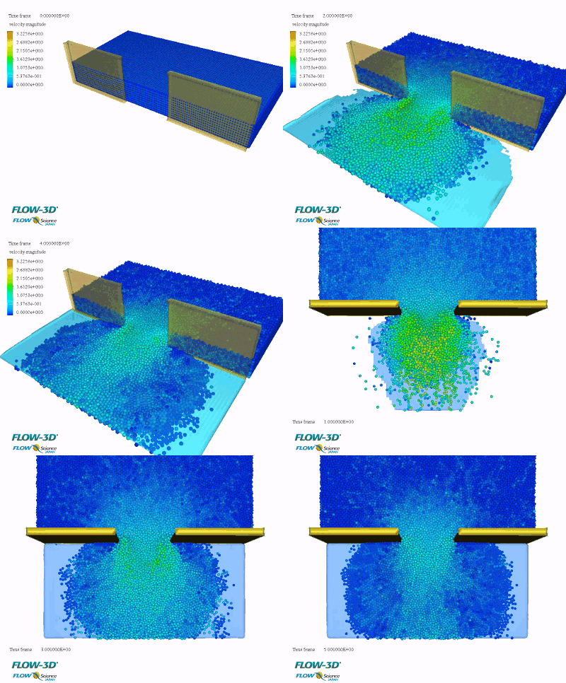
Debris flow, gravel, falling rock
 |
|
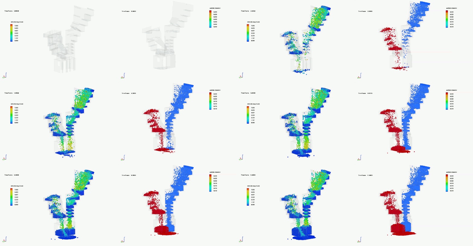
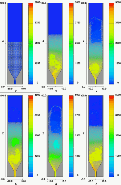
Fluidized bed, cyclone, stirrer
 |
 |
 |
전기 입자를 포함한 전기장 해석 등
|
|
|
Coarse Graining
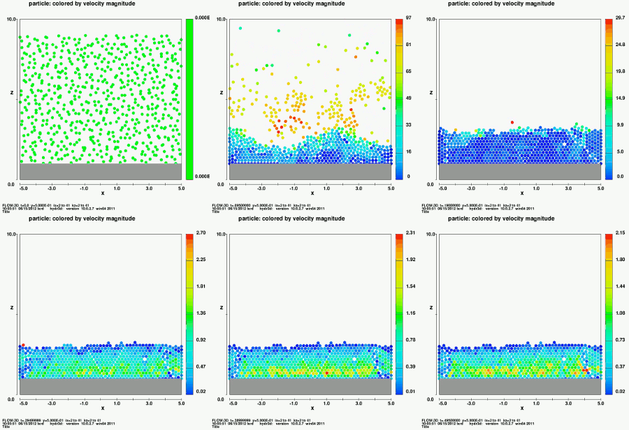
DEM은 일반적으로 다수의 입자를 필요로 하는 해석에 사용이 되고 있습니다. 다만 이 경우, 계산 부하가 높아지므로 현실적인 계산자원을 고려하면, 입자 수가 줄여 해석할 필요가 있습니다 .

Particle Size Increase 경우
DEM에서의 계산부하를 생각할 때는 입자모델에 의한 안정제한을 고려해야 하지만 서브타임스텝이라는 개념을 도입함으로써 입자의 경우와 유체의 경우의 타임스텝을 바꾸고 필요이상으로 계산시간을 들이지 않고 효율적으로 계산하는 것을 가능하게 하고 있습니다.
이를 통해 예를 들어 중자사 분사 시뮬레이션 실험에서는 이러한 문제로 자주 이용되는 빙엄 유체에서는 실험과의 정합성이 별로 좋지 않기 때문에 당사에서는 이전부터 입상류 모델이라는 모델을 개발하고 연속체로부터의 접근에서도 실험과의 높은 정합성을 실현할 수 있는 모델화를 해왔는데, 이번에 DEM을 사용해도 그것과 거의 같은 결과를 얻습니다. 할 수 있음을 확인할 수 있었다.


Reference :

(주)에스티아이씨앤디에서는 FLOW-3D 제품군의 사용자 교육을 지원하고 있습니다. 홈페이지에 안내되어 있는 교육 일정과 교육신청 절차를 참고하시어 교육을 받으실 수 있습니다.

댐, 하천의 여수로, 수문 등 구조물 설계 및 방류, 월류 등 흐름 검토를 하기 위한 유동 해석 방법을 소개하는 교육 과정입니다. 유입 조건(수위, 유량 등)과 유출 조건에 따른 방류량 및 유속, 압력 분포 등 유체의 흐름을 검토를 할 수 있도록 관련 예제를 통해 적절한 기능을 습득하실 수 있습니다.


해안, 항만, 해양 구조물에 대한 파랑의 영향 및 유체의 수위, 유속, 압력의 영향을 예측할 수 있는 해석 방법을 소개하는 과정입니다. 항주파, 슬로싱, 계류 등 해안, 해양, 에너지, 플랜트 분야 구조물 설계 및 검토에 필요한 유동해석을 하실 수 있는 방법을 알려드립니다. 각 현상에 대한 적절한 예제를 통해 기능을 습득하실 수 있습니다.
주조 분야 사용자들이 쉽게 접근할 수 있도록 각 공정별로 해석 절차 및 해석 방법을 소개하는 교육 과정입니다. 고압다이캐스팅, 저압다이캐스팅, 경동주조, 중력주조, 원심주조, 정밀주조 등 주조 공법 별 관련 예제를 통해 적절한 기능들을 습득할 수 있도록 도와 드립니다.


레이저 용접 해석을 하기 위한 물리 모델과 용접 조건들을 설정하는 방법에 대해 소개하는 교육 과정입니다. 해석을 통해 용접 공정을 최적화할 수 있도록 관련 예제와 함께 적절한 기능들을 습득할 수 있도록 도와 드립니다.
Powder Bed Fusion(PBF)와 Directed Energy Deposition(DED) 공정에 대한 해석 방법을 소개하는 교육 과정입니다. 파우더 적층 및 레이저 빔을 조사하면서 동시에 금속 파우더 용융지가 적층되는 공정을 해석하는 방법을 관련 예제와 함께 습득하실 수 있습니다.

상기 과정 이외의 경우 고객의 사업 업무 환경에 적합한 사례를 중심으로 맞춤형 교육을 실시합니다. 필요하신 부분이 있으시면 언제든지 교육 담당자에게 연락하여 협의해 주시기 바랍니다.

교육은 매월 정해진 일정에 시행되는 정기 교육과 고객의 요청에 의해 시행되는 비정기 교육이 있습니다. 비정기 교육은 별도문의 바랍니다.


Aerial Landslide Generated Wave Simulations
Aerial Landslide Generated Wave(ALGW)는 수역에 영향을 미치는 빠른 슬라이드의 결과이다. 이것은 암석에 의해 생성된 작은 파도 이거나, 3000만 입방 미터의 암석으로 인한 500m를 초과하는 파도 일 수도 있다.
공학적 관점에서 보면 ALGW는 근접한 해안을 따라 인간이 거주하는 인구/자산이 있는 수역에서 발생할 때 큰 관심을 가진다. 여기서 파동이 발생하면 해안선이 파손되고 홍수가 날수 있으며, 댐붕괴로 인한 사망까지 일으킬 수 있다(Müller-Salzburg, 1987). 결과적으로, ALGW에 의해 야기되는 최대 파도 상승을 예측하는 것은 경제적, 환경적, 안전상의 이유로 매우 중요합니다.
안타깝게도 분석적인 솔루션이 없는 매우 복잡한 문제로, 유체 역학적인 측면에서뿐만 아니라 지질학적인 관점(즉, 크기/기하학적인 슬라이드의 밀도 프로파일)에서도 마찬가지입니다. 이와 같이, 대부분의 현장 별 ALGW 최대 파형 예측은 확장된 물리적 모델을 사용하여 평가되었다. 일부는 전산유체역학(CFD) 소프트웨어를 기반으로 할 수도 있지만 비용이 많이 들며, 특히 풀 스케일 3차원 문제의 경우 정확성에 대한 논쟁의 대상이 되고 있습니다.
그러나 컴퓨터 하드웨어와 CFD소프트웨어가 계속 발전함에 따라 이제 CFD를 사용하여 ALGW를 실제로 시뮬레이션할 수 있게 되었습니다. 이와 같이 본 연구는 고 충실도의 물리적 모델 데이터를 FLOW-3D와 비교하여 ALGW를 CFD시뮬레이션을 검증하기 위한 지속적인 노력으로 진척시키는 것을 목표로 한다.
다음 절에서는 실제 및 수치 모델 설정에 대한 개요를 제공한다. 뿐만 아니라, 생성된 데이터와 간단한 비교를 제공한다.
Experimental Setup
물리적 실험은 Northwest Hydraulic Consultants 노스 밴쿠버, 캐나다 실험실에서 만들어졌고 실험을 거쳤다. 그것은 30° 경사의 서쪽 벽을 가진 0.5미터 폭의 수로, 45°의 경사진 동쪽 벽, 그리고 두개의 북쪽과 남쪽 측면에 수직 벽, 그리고 1.025m의 수평 단면을 가진 0.610m 너비의 수로로 구성되었다. ALGW를 생성하고 평가하기 위해, 45° 경사 노즈를 가진 0.177×0.305×0.305m의 아크릴 박스를 사용한 6초 시험을 사용했다.
이 슬라이드를 놓았을 때, 슬라이드는 (중력에 의해) 0.607m 심층수에 충돌하기 전에 서쪽 경사면에서 0.768m 아래로 이동했다. 그 후, 물을 통해 또 다른 1.05m를 이동하여 정지 블록을 치기 시작했다. 슬라이드 가속 및 변위뿐만 아니라 파고 높이는 6 초 실험 전체에 대해 100Hz의 주파수에서 기록되었다. 이 데이터를 수집하는 데 사용 된 도구는 다음과 같다.
테스트가 반복 가능하고 오작동이 발생하지 않았는지 확인하기 위해 테스트를 5 번 반복하고 각 장비에 대해 평균을 구했다.

Numerical Model Setup
물리적 실험의 전산화 된 3 차원 모델을 제작한 STL 파일을 FLOW-3D로 가져왔다. 일단 FLOW-3D에 들어간 3D 모델은 약 1,370 만개의 0.0075m 크기의 정사각형 셀로 이산화되었고, 벽을 둘러싸고있는 6 개의면 각각에 ‘wall’경계가 사용되었다.
슬라이드를 일반적인 이동 물체로 설정하고, 물리 모델로부터 수집 된 데이터(즉, 가속 및 변위 데이터의 후 처리)에 기초하여 속도가 주어졌다. 동서면 경사면의 표면 거칠기는 0.00025m으로 설정되었다. 모델링 된 유체는 293k의 물이었고, 동적 RNG 난류 모델이 기본 설정과 함께 사용되었다(implicit pressure solve; and, explicit viscous stress, free surface pressure, advection, moving object/fluid coupling solvers).
물리적 모델과 마찬가지로 FLOW-3D는 6 초의 시간을 시뮬레이트하지만 실제 모델과 같이 매 0.01 초가 아닌 0.02 초마다 데이터를 저장하였다(데이터 관리 관점에서 선택하였음).
Result
FLOW-3D 실험의 결과는 그림에 나와 있다. 4개의 웨이브 각각에 대해 실험 시간 동안 파고를 보여준다. 이와 같이, 제시된 파도 높이는 단순히 flume을 통해 전파되는 파도의 구현(즉, 2 차원의 경우에서 볼 수있는 것)이 아니라 오히려 여러 파도의 상호 작용으로 인한 파도 높이를 초래한다.
또한 길이 방향의 FLOW-3D 데이터(중심선에서)를 실제 모델 비디오 위에 겹쳐서 자유 표면의 FLOW-3D 글로벌 예측을 평가했다. 이것은 아래의 동영상에서 볼 수 있다.
그림과 위의 비디오를 보면 FLOW-3D 데이터가 웨이브 프로브 1, 2 및 3의 경우 물리적 데이터를 매우 잘 일치한다는 것을 알 수 있다. 하지만 웨이브 프로브 4에 대해서는 정확도가 떨어진다.
FLOW-3D 시간 데이터와 관련된 오류는 각 웨이브 프로브에 대한 RMSE (root-mean-square-error)를 취하여 평가된다.

Discussion
이 조사에서 실제 모델의 고 충실도 데이터는 ALGW로 최대 파도 상승에 대한 FLOW-3D 예측과 비교되었다. RNG 모형의 기본 설정을 사용하여 FLOW-3D는 주요 수역 내에서 파고를 정확하게 재현 할 수 있었다. 그러나 최대 파동은 약 43%가 넘었다.
최대 웨이브 런업을 줄이기 위해 몇 가지 대안인 FLOW-3D 물리 설정이 사용되었다. 그러나 43 % 이하로 떨어지는 것은 불가능했다. 이러한 대체 시뮬레이션에 대한 주목할만한 관찰은 다음과 같다.
[1] 3.5GHz 8 코어 AMD FX-8320 프로세서에서 약 6초의 시뮬레이션 시간이 대략 26시간 소요되었다.
References
Fritz, H. M., Hager, W. H., & Minor, H.-E. (2004). Near Field Characteristics of Landslide Generated Impulse Waves. Journal of Waterway, Port, Coastal & Ocean Engineering, 130(6), 287–302. doi:10.1061/(ASCE)0733-950X(2004)130:6(287)
Miller, D. J. (1960). Giant Waves in Lituya Bay Alaska (Geological Survey Professional Paper No. 354-C). Washington, D.C.: United States Government Printing Office.
Müller-Salzburg, L. (1987). The Vajont catastrophe— A personal review. Engineering Geology, 24(1–4), 423–444. doi:10.1016/0013-7952(87)90078-0

Indianapolis Storm-Water System
하수도 시스템은 액션영화의 도피 루트로 사용되지 않는 한 흥미롭지 않을 것입니다. 폭우로 인해 이산화탄소 수치가 올라갈 때까지 여러분은 그것에 대해 생각조차 하지 않을 것입니다. 불행하게도, 770개 이상의 오래 된 미국 도시들 아래에 있는 하수구 시스템은 심한 폭풍으로 오염 문제를 일으킵니다. 이러한 구형 설계는 하수 및 폭풍 유실을 위한 비용 효율적인 단일 스타일 파이프를 사용했으며 연결된 파이프로 강 및 호수에 하수를 내보냅니다(CSO).
1994년 미국 환경보호청(EPA)은 주로 북동부 및 그레이트 레이크 지역의 관련 지방 자치 단체들에게 CSO관련 문제를 줄이거나 제거하도록 하는 정책을 발표했습니다. (2000년 “Clean Water Act”의 일부로 법률화된 정책). 인디애나 폴리스(Indianapolis)는 가벼운 비 폭풍으로 인해 하수 오물의 백업 및 범람이 발생할 수 있는 도시 중 하나였으므로, 주요 건설 조건에서 2025년까지 문제를 해결하는 것이 필요하였습니다.
인디애나 폴리스는 국제 디자인 회사인 AECOM에 Citizens Energy Group이 건설하고 있는 3개의 깊은 암석 저장 터널 중 첫 번째를 설계할 것을 요청했습니다. 총 25마일인 이 시스템은 대규모 지하 펌프장과 기존의 하수구에서 CSO를 수직으로 떨어뜨리는 연결 구조물을 포함합니다. 첫 번째 터널의 경우, 강우가 가라 앉은 후에 3 개의 커다란 강하 구조물이 CSO를 저장 터널로 전환하여 후속 처리를 수행했습니다.
프로젝트를 해결하기 위해 AECOM은 여러 가능한 낙하 구조물 설계의 동작을 시뮬레이션하기 위해 FLOW-3D를 선택하여, 구축 및 평가 예산이 책정 된 물리적 모델에 대한 재 작업의 필요성을 최소화했습니다. 테스트 결과는 예측 값과 일치하였으므로 재설계가 필요하지 않았습니다. 또한, 이제 AECOM은 유압 설계작업의 첫 번째 단계를 일반적으로 CFD시뮬레이션을 사용합니다.
Large Scale Project on a Tight Delivery Schedule
촉박한 납품 일정에 따른 대규모 프로젝트
20세기에 건설된 하수 처리장은 주거용, 상업용, 환경유출물의 유출로 무엇을 해야 할 것인지에 대한 새로운 인식을 가져다 주었습니다. CSO 방전은 정상적으로 운영되는 동안 처리시설로 직접 이동되며 모든 과정이 양호하게 운영됩니다. 불행하게도, 대규모 폭풍이 발생하는 동안, 발전소들의 초과 용량문제를 피하기 위해 인근 수역으로 과도한 유량을 방출합니다. 이들 배출은 기름과 살충제, 야생동물 배설물에 이르기까지 다양한 오염 물질을 포함합니다.
고무적인 성공의 신호로, 1990 년대에 착공된 새로운 CSO 분리, 저장 및 처리 시설로 오염의 영향에 대해 67 %의 개선을 이루었지만, 여전히 많은 연구가 이루어져야 합니다. 인디애나 폴리스의 경우, 인디애나 폴리스시 공공사업부가 CSO 장기 통제계획을 준비한 2008년에 그러한 노력이 시작되었습니다. 정상적인 처리 공장에서 처리 할 수 있을 때까지 오버플로우가 발생하는 “저장 및 운송”접근법의 핵심은 인디애나 폴리스 터널 저장 시스템 또는 인디애나라고 합니다.
이 시스템의 첫번째 단계는 딥 록 터널 커넥터(DRTC)라고 불리는 1억 8천만달러 가치의 프로젝트입니다. DRTC는 길이 7마일의 18피트 직경의 지하 터널로, 기존의 인디애나 폴리스의 3개의 서버 대 계층 유출 연결의 흐름 경로를 다시 만들 것입니다(그림 1). 목표는 과잉 강우 유출을 기존 하수구와 새 터널 사이의 낙하 구조를 통해 이들 대피소에서 거대한 터널로 안전하게 재배치하고, 폭풍 후 처리를 위해 처리장으로 펌핑 될 수있을 때까지 유지합니다.

Fig. 1. City of Indianapolis Deep Rock Tunnel Connector (DRTC), a “storage and transport” concept being built to handle combined sewage overflow (CSO) during heavy storms. Three vertical drop structures will capture this flow and divert it downwards to 18-foot-diameter storage tunnels running more than 250 feet underground; the tunnels store the CSO until sewage treatment plant capacity becomes available. (Image courtesy Citizens Energy Group)
평균적으로 지표면 아래 250피트 깊이에서, DRTC는 건설과 궁극적인 운영 동안 위의 주변 지역에 대한 혼란을 최소화하도록 설계되었습니다. 그러나 이 프로젝트의 규모와 복잡성은 AECOM의 과제에 긴급성을 더했습니다. 세 장소 각각에 대한 가능한 낙하 구조 설계와 평가, 구조물 설계의 60%를 7개월 이내에 마무리 지었습니다.
이러한 구조물의 목적은 표준 도시 하수 시스템에서 깊은 저장 터널로 하수 흐름을 전달하는 동시에, 효율적 손실( 느린 속도 또는 백업)과 장기적인 도심을 방지하는 것입니다. 각 섹션의 크기와 모양이 유입 흐름의 볼륨 및 속도와 세심하게 일치하지 않을 경우 발생할 수 있는 구조적 손상입니다.
AECOM의 수석 기술 전문가인 라이언 에디슨 컨설턴트는 계약의 스케줄링 요구 사항이 유효성 검사를 위해서는, 단 하나의 모델에만 물리적 건물과 테스트 활동을 제한할 것이라는 것을 알게되었습니다. 다른 주요 건설 프로젝트에 15년간 FLOW-3D 시뮬레이션 소프트웨어를 사용해 왔기 때문에, 난류, 과전압 및 에너지 낭비를 예측하는 능력은 충분하지 않고 디자인 프로젝트에 적합하다고 자신했습니다. 또한 여러 검증(what-if) 시나리오를 실행하기 위한 소프트웨어 옵션을 통해 설계 세부 사항을 다시 실행해야 하는 위험을 최소화할 수 있었습니다. 변경 사항이 적용될 경우 상당한 이점은 여러개의 병렬 시공 트랙이 있는 프로젝트에 있습니다.
시간 제약에도 불구하고, 에디슨은 특히 이 도전에 만족했습니다. 왜냐하면 “CFD로 드롭 구조 설계를 만들고 물리학에서 이것들은 너무 큰 구조이기 때문입니다.”라고 그는 말합니다. 그것들은 CFD는 실제로 사용되지 않는데 보통 물리적 모델이나 손으로 계산하는 것으로 이루어집니다.
DRTC 프로젝트를 위해서, 그는 먼저 시뮬레이션된 작동 조건에 대해서 컴퓨터 설계를 테스트할 것입니다. 에디슨은 3차원의 일시적이고 격동적인 흐름 조건을 모델링 할 수 있는 소프트웨어 패키지인 FLOW-3D를 사용했습니다. 각 설계에 대한 계산 메쉬를 변경하지 않고도 여러 설계 지오 메트리를 모델링 할 수 있는 기능이였습니다.
시뮬레이션 데이터로 무장한 에디슨은 그 결과를 아이오와 대학교 II. 시설에서 시험한 1:10 크기의 물리적 모델의 작동 데이터와 비교하였습니다. (후자는 원래 아이오와 유압 연구소라고 불렸지만, 지금은 그룹의 다양한 범위를 반영하여 IIHR-Hydroscience & Engineering으로 알려져 있습니다.)
Zeroing in on the Drop-Structure Challenge
드롭 구조 과제에서 영점 조정
가장 제한적인 DRTC 사이트의 지오 메트리는 CSO 008로 지정된 레귤레이터에서 발생합니다. 기존 CSO 레귤레이터(기울기 약 75피트 아래)를 새 18피트 직경의 수집 터널과 연결하려면, 이 위치에서 150피트 이상의 수직 방향 주행이 필요합니다. 각 낙하 구조에 7백만달러 이상이 소요되는 경우, 프로젝트 관리자들은 물리적 모델이 구축된 후 비용과 시간이 많이 소요되는 재설계가 필요한 가능성을 낮추려고 애썼습니다.
역사적으로 낙하 구조는 이전 프로젝트를 적용하여 설계된 후 축소 모델로 구축되었으며, 테스트만으로도 6개월 이상이 소요될 수 있습니다. 가속화된 이 프로젝트에서, 2009년 가을에 시작한 AECOM의 초기 과제는 두가지 표준 개념 중에서 하나를 선택하는 것이었습니다. 포장-파운드 스타일과 접선 vortex버전, 둘 다 시속 35마일의 폭풍이 몰아치는 물 속에서 속도를 늦추고 통제하기 위해서 직접 계산 및 FLOW-3D에서 결정한 일반 구조 직경 및 구성 요소 크기를 사용한 초기 CFD분석으로, AECOM은 시공 가능성 및 비용 고려 사항을 평가하는 데 사용했습니다.
CSO 008의 현장 요구 사항과 비용 효율성을 고려할 때, 시 당국과 AECOM은 접선 소용돌이 낙하 구조를 선택했습니다. 이 설계의 핵심 요소는 흐름을 먼저 환상적인 제트로 유도한 다음, vortex 유도 나선형 흐름을 생성하는 테이퍼(확대) 접근 채널에 의해 공급되는 수직 튜브(드롭 샤프트)입니다. 이 통제 된 하강은 속도가 느려지고 하루 3 억 갤런 (mgd) 이상에 이르는 흐름을 안전하게 처리합니다. 스토리지 터널의 파괴적인 난류를 방지하는 것이 핵심 목표이므로 드롭 샤프트 흐름의 사전 차단이 설계의 핵심입니다.
구조 자체는 6 개의 주요 부분으로 구성됩니다. 1) 접근 채널 (기존의 하수 터널에서 나온 것), 2) 수평 흐름을 넓히고 수직 드롭 샤프트로 수평 흐름을 전달하는 직사각형 전이 테이퍼 채널, 3) 드롭 샤프트 자체 4) 탈 기실 (유량을 수평 방향으로 방향을 바꾸고 공기 유입을 감소시키는), 5) 수직 공기 배출구를 통해 낙하에서 유입 된 공기를 제거하고 적하 유체의 공기 코어가 열려 있고 6) 탈기 챔버와 저장 터널 챔버를 연결하는 파이프 (adit) (그림 2).

Fig. 2. CAD diagram of proposed Indianapolis DRTC combined sewage overflow (CSO) vertical drop structure, showing approach channel, taper channel and vortex dropshaft. Using FLOW-3D CFD analysis software, AECOM simulated the flow behavior, gaining confidence in the system performance prior to physical model testing. (Image courtesy AECOM)
Prediction of Shrinkage Defects During Investment Casting Process
This article was contributed by Dr. S. Savithri, Senior Principal Scientist at CSIR-NIIST
인베스트먼트 주조공정은 가장 오래된 주조 공정 중 하나로 기원전 4000년 이후에 보편화되었습니다. 이 과정은 용해된 금속을 소모품패턴으로 생성된 세라믹 쉘에 주입하는 과정을 수반합니다. 일찍이 그것은 금, 은, 구리와 청동 합금으로 장신구와 우상을 만드는데 사용되었습니다.
인베스트먼트 주조공정은 1897년 아이오와 주, 위원회 블러프스의 Barabas Frederick Philbrook이 묘사한 대로 치과의사들이 왕관과 인레이를 만들기 위해 그것을 사용하기 시작한 19세기 말 현대 산업공정으로 사용되기 시작했다. 1940년대에는 제2차 세계대전 당시 기존 방법으로는 형성될 수 없거나 지나치게 많은 가공이 필요한 특수 합금의 정밀 순모형 제조 기술에 대한 수요로 인해 투자 주조 공정이 증가하였다.
오늘날 투자 주조 공정은 표면 마감 및 치수 정확도가 우수하여 거의 순 형태에 가까운 철, 비철 및 초합금의 소형 산업용 부품을 생산하는데 주로 사용됩니다.
인베스트먼트 주조 공정은 다음 네 가지 주요 단계로 구성됩니다.

Figure 1. Solid model of the casting geometry
인베스트먼트 주조 공정에서 얻은 부품은 많은 중요한 용도에 사용되므로 내부적인 결함이 없어야 합니다. 투자 주조 공정에서 발생하는 주요 결함은 세라믹 포함, 균열, 변형, 플래시, 주탕불량, 수축, 슬래그 포함, 탕경계등입니다. 얻은 주조물의 품질을 예측하려면 금속-몰드 열 전달계수, 주입 온도 등 다양한 주조 공정 매개 변수의 영향을 연구해야 합니다. 즉, 쉘 두께 및 쉘 열 전달계수가 그것입니다. 현대 컴퓨터 시스템 및 시뮬레이션 소프트웨어의 출현과 함께 금형 충진 및 응고 시뮬레이션은 주조공장에서 결함을 예측하고 설계를 최적화하는데 점점 더 많이 사용되고 있습니다.
이 연구의 주요 목적은 투자 주조 공정에서 주요 요소인 복사 열 전달과 인베스트먼트 주조공정에 고유한 쉘 금형이 FLOW-3D에서 효과적으로 구현될 수 있는지를 조사하는 것입니다. FLOW-3D를 사용하여 간단한 형상을 위한 인베스트먼트 주조공정의 주입 및 응고 시뮬레이션을 수행함으로써 두 구성요소의 서로 다른 효과를 조사합니다. 다양한 위치에서 얻은 온도의 수치는 문헌 [1]에보고 된 실험 결과로 검증됩니다. 복사 열 전달계수, 쉘 몰드 두께, 탕구 및 게이트의 위치에 대한 영향도 조사했습니다.

Figure 2. Shell mold
Methodology
현재 연구에서 사용된 계산 형상은 그림 1에 나와 있습니다. 쉘 몰드는 다음 단계를 사용하여 작성되었습니다.

Figure 3. The view of the two mesh blocks for the creation of a void with discretization
쉘 몰드 용 STL 파일을 만든 후 파일을 구성 요소 1로 새 시뮬레이션으로 가져오고 이전에 작성한 주조 형상을 하위 구성 요소로 가져오고 유형을 ‘hole’으로 선택합니다. 쉘 몰드와 함께 주조 형상이 그림 2에 나와 있습니다. 이것은 우리의 계산 영역으로 사용됩니다. 다음은 계산 영역을 cubical/rectangular셀로 분할하기 위한 메쉬를 만드는 것입니다. 메쉬 블록을 작성하여 FLOW-3D에서 메쉬를 생성합니다. 현재의 작업을 위해 우리는 2.5mm의 고정된 셀 크기가 선택된 그림 3에 표시된 균일한 메쉬 옵션을 선택했습니다. 입력 위치 주변에 메시 블록 2가 사용되는 현재 시뮬레이션을 위해 메시 블록 2개가 생성되었습니다. 쉘과 주변 공기 사이의 30°C에서의 열 전달을 고려하여 쉘 주위에 보이드 영역이 정의됩니다. 이 영역은 ‘열 전달 유형 1’이 있는 보이드 영역으로 선택되며 셸과 주변 공기 사이에 열 전달 계수 값이 지정됩니다. 열 전달 유형 1은 방사선을 포함한 종합 열 전달 계수가 됩니다.
쉘 주형에 선택된 재료는 zircon이며 열 특성은 Sabau and Vishwanathan에 의해 수행된 실험에서 얻을 수 있습니다[2]. 표 1은 연구에 사용된 재료에 대해 지정된 값을 보여 줍니다.
| MATERIAL | PROPERTY | VALUE | UNIT |
| Fluid –AluminiumA356
alloy |
Density | 2437 | kg/m³ |
| Thermal conductivity | 116.8 | W/(mK) | |
| Specific heat | 1074 | J/(kgK) | |
| Latent heat | 433.22 | kJ/m³ | |
| Liquidus temperature | 608 | °C | |
| Solidus temperature | 552.4 | °C | |
| Zircon Mold | Thermal conductivity | 1.09 | W/(mK) |
| Specific heat* Density | 1.63E+06 | J/( m³K) |
Initial and boundary conditions used are show in Table 2.
| Mold temperature | 430°C |
| Melt pouring temperature | 680°C |
| Filling time | 7 s |
| Interface heat transfer coefficient | 850 W/m2K |
| Heat transfer coefficient between ambient and mold (radiation effect) | 30 -100 W/m2K |
Table 2. Initial and boundary conditions used for the simulation
탕구저에 들어가는 용융물의 초기 속도와 온도는 메시 블록 2의 상단 경계에서 속도 경계 조건으로 주어집니다. 기본적으로 다른 모든 경계는 대칭 유형으로 설정됩니다.
Results & Discussion
Validation with reported experimental results
충전 및 응고 동안 냉각 곡선을 얻기 위한 실험에서 Sabuet.al[1]에 의해 선택된 네 개의 위치가 검증 목적으로 사용되었습니다. 그들은 C1, C2, S11, S12및 S21로 언급됩니다. C1과 C2지점은 주물의 플레이트의 중심에 있으며 S11, S12및 S21은 모두 쉘에 위치합니다. 이러한 위치에서의 온도 변화는 그림 4와 같습니다.
온도 프로파일의 수치 및 실험결과의 차이가 허용한계 안에 있음을 알 수 있습니다. 프로브 포인트 C1과 C2의 경우, 수치와 실험 결과 사이의 차이는 응고 중에 5%, 응고 후 냉각 시 12% 이내입니다. 쉘의 점에 대한 수치 결과는 실험 결과보다 약 5% 높습니다. 이는 쉘 재료에 열 물리학적 특성을 할당할 때 발생하는 가정과 쉘 열 전달 계수의 값 때문일 수 있습니다.
Fill sequence & solidification pattern for two different sprue locations
두 가지 다른 스프 루 위치의 채우기 순서 및 응고 패턴
2 개의 상이한 탕구 위치에 주물충전 순서는5a 및5b에 나와 있습니다. 최종 탕구가 더 많은 스플라인을 생성하므로 결함으로 이어질 수 있습니다. 탕구가 중간에 놓여지면 흐름은 보다 균일 해지고 두 주조 단면에서 비슷한 온도 분포를 보입니다. 50 % 응고 후의 온도 프로파일의 2D 도면은 두 경우 모두 그림 5c 및 5d에 나와 있습니다. 수축 위치에서 볼 때 두 탕구 위치가 결함을 일으키는 것은 분명합니다.

Figure 5a. Fill sequence at different time intervals when the sprue is located at one end

Figure 5b. Fill sequence at different time intervals when the sprue is located in the middle

Figure 5c. 2D temperature profile after 50% solidification when the sprue is located at one end

Figure 5d. 2D temperature profile after 50% solidification when the sprue is located in the middle
Effect of shell thickness
인베스트먼트 주조에 대한 쉘 두께의 효과를 연구하기 위해 두께가 7.2, 10, 15 및 20 mm인 주물을 선정하였습니다. 그림 6a 및 6b는 주조품의 특정 위치에서 냉각 곡선을 나타내며, 이는 C1으로 나타내고 쉘 몰드 내의 특정 위치에 있으며, 응고 중에 S11로 나타납니다. 세라믹 쉘의 두께가 7.2 mm에서 15 mm로 증가하면 냉각 속도가 감소하여 응고 시간이 길어지는 것을 볼 수 있습니다.
Effect of shell heat transfer coefficient
셸 열 전달 계수는 열이 셸 금형의 외부 벽에서 방사선을 통해 주변 공기로 열을 방출하는 속도를 나타냅니다. 이 효과를 조사하기 위해 열 전달 계수의 값을 20에서 80W/m2K까지 다양하게 했습니다. 7a 및 7b로부터, h의 변화는 주조 재료 및 쉘의 냉각 속도에 중요한 영향을 미친다는 것을 알 수 있습니다. 열 전달 계수가 20에서 80W/m2K로 증가하면 C1에서의 응고 시간이 812 초에서 334 초 (약 44 %)로 감소되었음을 알 수 있습니다. 따라서, h의 값을 변화시키는 것은 주물의 미세 구조에 영향을 미칩니다.

Figure 6a. Temperature profile at location C1 (casting) for the casting geometry where the sprue is located at one end for various shell thickness values
F
Figure 6b. Temperature profile at location S11 (shell) for the casting geometry where the sprue is located at one end for various shell thickness values

Figure 7a. Temperature profile at location C1 (casting) for the casting geometry where the sprue is located at one end for various heat transfer coefficient values between the shell mold & ambient

Figure 7b. Temperature profile at location S11 (shell) for the casting geometry where the sprue is located at one end for various heat transfer coefficient values between the shell mold & ambient
Conclusions
인베스트먼트 주조 공정의 몰드 충진 및 응고 시뮬레이션은 FLOW-3D를 사용하여 수행되었습니다. 주조 공정에 대한 주조 매개변수의 영향을 연구하기 위해 파라메트릭 연구가 수행되었습니다. 본 연구에서 다음과 같은 결론을 도출 할 수 있습니다.
References
Sabau, A.S., Numerical Simulation of the Investment Casting Process, Transactions of the American Foundry Society, vol. 113, Paper No. 05-160, 2005.
Sabau, A.S., and Viswanathan, S., Thermophysical Properties of Zircon and Fused Silica-based Shells used in the Investment Casting Process, Transactions of the American Foundry Society, vol. 112, Paper No. 04-081, 2004.
Design and CFD Analysis
설계 및 CFD분석
일반적인 소용돌이 설계는 널리 받아들여지고 있지만, 각 낙하 구조는 최적의 접선 흐름 특성을 보장하기 위해 인디애나 폴리스의 위상에 맞는 적절한 크기를 가져야 했습니다. 특히, 가능한 설계에 대한 AECOM의 계획은 세가지 목표를 가지고 있었습니다. 결합된 접근법과 테이퍼 채널을 짧은 길이로 제한하는 현장, 고유의 제약이 있었는지를 결정합니다. 허용 가능하지만 접근 방식에서 과도한 난류 조건이 발생하지 않았습니다. 테이퍼 채널에 안정적인 흐름 조건이 존재하는지 확인하고 다양한 흐름 조건에서 흐름 안정성을 평가했고, 논리적 기준점은 밀워키 인라인 스토리지 프로젝트라고 불리는 잘 알려지고 문서화된 시스템이었습니다.
Edison은 DRTC 프로젝트 규모에 맞춰 H-4로 지정된 Milwaukee 드롭 구조 설계를 기반으로 초기 설계를 기반으로했습니다.
166 피트의 기본 낙하 길이를 포함하고 체적 유량, 벽, 대칭 및 기타 초기 매개 변수를 지정하는 FLOW-3D 분석을 설정합니다.
그는 우리가 CFD를 통해 발견한 것은 밀워키에서 이 디자인을 사용하면 우리의 어플리케이션에 잘 맞지 않는다는 것이라고 말합니다. FLOW-3D는 이것을 보여 주고 있었기 때문에 CFD를 사용하여 변형을 시도하고 우리의 수정된 디자인을 고안했습니다.
더 넓은 접근 경로, 더 넓은 테이퍼 및/또는 더 깊은 테이퍼 깊이를 사용한 수정은 에디슨은 FLOW-3D에서 각 변동 사항을 설정하는 것이 매우 빠르다고 말합니다. (그림 3,4,5). 개선의 진전은 고무적이었습니다. 시뮬레이션 결과의 높은 수준은 심지어 절삭(침식)을 개선하기 위해 드롭 축의 바닥에 의문스러운 플레이트가 수직 흐름이 수평으로 전환되는 난류 분리 및 감소가되도록 기능을 추가하도록 설득했습니다.

Figs. 3, 4 and 5. Tangential drop structure flow simulated with FLOW-3D. Structure dimensions were optimized through multiple design iterations. (Image courtesy AECOM)
9번째 설계 변동에 대한 FLOW-3D 출력 동작인 V9는 접근 섹션을 확장했으며, 모든 흐름 볼륨 레벨에서 300mg/d까지 양호한 흐름 안정성을 보였으며 유압식 점프는 없었습니다. 그리고 양호한 Froude numners(유체 움직임에 미치는 중력의 영향을 나타내기 위해 사용되는 치수 없는 수량), 2010년 2월부터 AECOM이 물리적 시험과 검증을 위해 선택하였습니다(그림 6). 그 계획은 아이오와 연구소의 시험 결과에 기초하여 CFD와 최적화를 추가하는 것이였습니다.

Fig. 6. Scale model (1:10) of vertical drop structure, tested at University of Iowa IIHR Hydroscience & Engineering facility. (Image courtesy AECOM)
에디슨은 V9에서 결정된 치수 매개 변수에 대해 그 디자인을 아이오와 주에 가져가서 CFD를 이용해 만들었는데 완벽하게 작동했습니다. (II.)직원들은 실제로 무언가를 설치한 것은 이번이 처음이며, 변경하라고 말할 만한 것이 아무것도 없다고 말했습니다. 측정된 데이터는 드롭 샤프트 연결 구조 내의 수면 높이, Adit내 공기 침투의 정량, 벤트 샤프트 위로 공기 흐름을 포함했습니다. 흐름이 증가함에 따라 와류량이 증가함에 따라 축 벽에 부착되어 탈산소까지 원활하게 회전하는 모습이 포착되었습니다(그림 7).
에디슨은 후속 실험을 위해 여러번 시험장을 돌아다녔습니다. 물리적 모델이 처음부터 올바르게 작동했기 때문에 시험 프로그램을 확장할 시간이 있었습니다. “재미 있는 것은 환기구를 움직이는 것과 같이 우리가 궁금했던 것들을 탐구해서 지적으로 그것을 가지고 놀 시간이 있었다는 것입니다.” 에디슨은 예정보다 앞서 있었기 때문에 잔여 프로젝트 시간을 이용해 탈염소와 adit 내의 유압 장치를 조사할 수 있었습니다.

Fig. 7. Operation of scale-model vertical drop structure, showing test run of 300 million gallons per day (mgd). Flow vortex development shows good rotation and attachment to the shaft wall all the way down to the de-aeration chamber. No design modifications were necessary to the simulated design. (Image courtesy AECOM)
Final Results
AECOM은 2010년 7월 DRTC에 대한 전반적인 작업을 마쳤습니다. 2013년 3월부터 18구경 터널을 굴착하기 시작했고, CSO드롭 구조 3개(CFD로 설계된 나머지 2개의 구조물만 있음)는 모두 현재 공사 중입니다.
에디슨의 의견으로는, 토목 공학은 전체적으로 CFD를 채택하는 데 느린 편이었습니다. 이를 입증하기 위해 그는 인천 국제 공항을 처음 방문한 당시 접선 소용돌이 모형의 소위 “묘지”에서 본것을 기술했습니다. 그러나 그는 이들을 다시 처리해야 했다고 말했습니다. 그는 유압 설계를 위한 시뮬레이션 사용으로 판매되는 것을 권장하고 있습니다.
에디슨은 DRTC노력을 요약하면서 “정말 재미 있었습니다. 물리적 모델링이 필요한 위치에 대해 더 자세히 알아보았고, 그렇다면 어떤 경우에는 순수한 RAID기반 설계를 수행할 수 있습니다. 많은 DRTC작업들이 그것의 증거입니다. 물리적 모델은 실제로 필요하지 않았지만 검증을 통해 위험을 줄일 수 있었습니다. 프로젝트에서 이 두가지를 모두 수행할 수 있었다는 것은 믿을 수 없는 일입니다.”라고 말했습니다.
This article first appeared in WaterWorld Magazine.
레이저 파우더 베드 퓨전 (L-PBF) 첨가제 제조에는 복잡한 물리적 공정이 필요합니다. 특히, 흡수 된 레이저 빔 에너지는 입자를 녹여 강한 유체 흐름이 표면 장력 기울기 (또는 Marangoni 전단 응력)에 의해 주로 발생하는 용융 풀을 형성합니다. 열 전달 및 유체 유동은 분말 베드 내의 분말 입자의 국부적 배열에 의해 영향을 받으며, 이는 위치에 따라 다를 수 있습니다. 매우 일시적인 유체 흐름으로 인해 용융 된 풀 표면 (자유 표면)의 형상이 끊임없이 진화하여 최종 표면 품질에 영향을 미칩니다.
본 연구에서는 분말 포장 특성, 공정 변수 및 용융 풀 역학이 표면 품질에 미치는 영향을 정량적으로 이해하기 위해 두 가지 모델을 순서대로 사용합니다. 첫 번째 모델은 오픈 소스 이산 요소 방법 (DEM) 코드 인 Yade를 기반으로 개발 된 분말 입자 포장 모델입니다. 입자 적층 정보 (예를 들어, 개별 입자의 위치 및 반경)를 제공한다. 이러한 정보는 FLOW-3D를 기반으로 한 3D 과도 용융 풀 모델 인 두 번째 모델에 입력됩니다. 두 모델의 세부 사항은 문헌 [1]에 나와있다. FLOW-3D를 기반으로 한 용융 풀 모델의 특징을 요약하면 다음과 같습니다.
과도 유체 흐름 시뮬레이션은 그림 1에서와 같이 1000 μm (길이), 270 μm (너비) 및 190 μm (높이) 치수의 3D 계산 영역에서 수행됩니다. 도메인은 50 μm 두께의 층 의 분말 입자를 90㎛ 두께의 기판 위에 놓았다. 도메인의 미리 알림은 처음에는 무효로 채워집니다. 분말 층 형상은 DEM 시뮬레이션의 결과를 사용하여 초기화됩니다. 총 셀 수를 줄이면서 공간 분해능을 극대화하기 위해 메쉬 크기가 기판 / 파우더 레이어 인터페이스를 향하여 기판에서 9 μm에서 3 μm까지 연속적으로 감소하는 편향 메쉬가 사용됩니다. 메쉬 크기는 파우더 레이어와 그 위의 빈 공간에서 3 μm로 일정하게 유지됩니다. 총 셀 수는 143 만입니다.
경계 조건의 경우, 가우시안 분포에 기초한 소정의 열유속이 분말 층의 상부 표면에 부과되어 X 방향을 따라 이동하는 레이저로부터의 열 입력을 나타낸다. 온도에 따른 표면 장력은 FLOW-3D에서 사용 가능한 개선 된 표면 장력 모델을 사용하여 포함됩니다. 다른 열 – 물리적 특성의 경우, FLOW-3D 데이터베이스에서 사용 가능한 IN718 합금에 대한 데이터가 사용됩니다.
약 600 마이크로 초 길이의 L-PBF의 과도 시뮬레이션은 약 40 시간의 클럭 시간이 소요되었으며 인텔 ® 제온 ® 프로세서 E5335 및 4GB RAM의 중간 정도급의 워크 스테이션에서 수행되었습니다.
그림 2는 시간 = 55 μs에서 용융 풀 내의 온도 등면 및 속도 벡터의 종단면도 (즉, 레이저 이동 방향에 평행 한 단면)를 도시한다. 용융 된 풀 경계는 1608.15 K에서 등온선으로 표시되며, IN718의 액상 선 온도입니다. 이 그림의 오른쪽에 표시된 것처럼 입자는 부분적으로 용융 풀로 용융됩니다. 용융 된 풀 표면 근처에서, 용융 금속은 레이저 빔 바로 밑의 중심 위치에서 풀의 후단으로 당겨진다. 풀 표면 근처의 용융 금속의 이와 같은 역류는 풀의 후단을 향해 고비를 형성하는 동안 레이저 빔 아래에서 움푹 들어간 표면 프로파일을 생성한다. 다음에서 논의되는 바와 같이, 혹 모양은 볼 결함의 형성을 초래할 수 있습니다.

볼링(balling)은 그림 3에서와 같이 용융 풀이 불연속으로 분리되어 분리 된 섬으로 갈라질 때 발생할 수있는 결함입니다.이 그림에서 알 수 있듯이 레이저 빔 바로 아래의 용융 풀은 안정적이지 않으며 후단이 빠르게 분리됩니다 정면에서 분리 된 섬을 형성합니다. 분리는 그림 3 (c)와 같이 용융 풀의 중간에있는 보이드에서 시작된다. 이 공극은 레이저가 앞으로 계속 이동하면서 팽창하여 결국 용융 된 풀을 두 부분으로 나눕니다. 도 3 (e) 및 (f). 공극의 형성과 그 팽창은 표면 장력 구배 (Marangoni 효과)에 의해 강한 후진 유동에 의해 유발됩니다.
L-PBF에서의 열 전달 및 유체 흐름의 3D 과도 시뮬레이션은 볼 결함의 형성을 정량적으로 이해하기 위해 수행됩니다. 단순한 선형 트랙 만 시뮬레이션되었지만, 본 모델은 최종 빌드 품질의 중요한 속성 인 용융 풀 표면 프로파일 및 볼링 결함 형성을 연구 할 때 분말 레벨 시뮬레이션의 중요성을 보여줍니다.
뿐만 아니라 위의 금속 분말 소결 시뮬레이션은 금속 3D 프린팅(Metal 3D Printing) 산업의 핵심 기술이며 차후 많은 연구와 응용이 기대되는 분야가 될 것입니다.
이 자료는 수상 번호 N00014-14-1-0688하에 미해군 연구소(ONR)가 지원하는 연구과제에 기초로 작성되었습니다.
[1] Y.S. Lee and W. Zhang, Mesoscopic Simulation of Heat Transfer and Fluid Flow in Laser Powder Bed Additive Manufacturing, In: 2015 Annual International Solid Freeform Fabrication Symposium, Austin, TX, pp. 1154-1165, August 2015.
다음은 적층 제조 및 용접 참고 문헌의 기술 문서 모음입니다. 이 모든 논문에는 FLOW-3D AM 결과가 나와 있습니다. FLOW-3D AM을 사용하여 적층 제조, 레이저 용접 및 기타 용접 기술에서 발견되는 프로세스를 성공적으로 시뮬레이션하는 방법에 대해 자세히 알아보십시오.
2024년 11월 20일 update
121-24 Lovejoy Mutswatiwa, Lauren Katch, Nathan John Kizer, Judith Anne Todd, Tao Sun, Samuel James Clark, Kamel Fezzaa, Jordan Lum, David Matthew Stobbe, Griffin Jones, Kenneth Charles Meinert Jr., Andrea Paola Argüelles, Christopher Micheal Kube, High-speed synchrotron X-ray imaging of melt pool dynamics during ultrasonic melt processing of Al6061, Communications Materials, 5; 143, 2024. doi.org/10.1038/s43246-024-00584-3
120-24 Mysore Nagaraja Kishore, Dong Qian, Masakazu Soshi, Wei Li, Conforming mesh modeling of multi-physics effect on residual stress in multi-layer powder bed fusion process, Journal of Manufacturing Processes, 124; pp. 793-804, 2024. doi.org/10.1016/j.jmapro.2024.06.033
113-24 Yusufu Ekubaru, Takuya Nakabayashi, Tomoharu Fujiwara, Behrang Poorganji, Processing windows of Ni625 alloy fabricated using direct energy deposition, Advanced Engineering Materials, 2024. doi.org/10.1002/adem.202400962
111-24 Ruijie Liu, Melt pool dynamic modelling for the titanium-based metal additive manufacturing process, Thesis, The University of Auckland, 2024.
104-24 Ju Wang, Meng Li, Huarong Zhang, Zhe Liu, Xiaodan Li, Dengzhi Yao, Yuhang Wu, Qiong Wu, Xizhong An, Shujun Li, Jian Wang, Xing Zhang , Cumulative effects of powder beds and melted areas on pore defects in electron beam powder bed fusion of tungsten, Powder Technology, 443; 119971, 2024. doi.org/10.1016/j.powtec.2024.119971
100-24 Xuesong Gao, Aryan Aryan, Wei Zhang, Numerical analysis of rotating scans’ effect on surface roughness in laser-powder bed fusion, Journal of Materials Research and Technology, 30; pp. 8671-8682, 2024. doi.org/10.1016/j.jmrt.2024.05.214
95-24 Yongbiao Wang, Yue Zhang, Junjie Jiang, Yang Zhang, Hongyang Cui, Xintian Liu, Yujuan Wu, Cross-scale simulation of macro/microstructure evolution during selective laser melting of Mg–Gd–Y alloy, Metallurgical and Materials Transactions B , 2024. doi.org/10.1007/s11663-024-03104-3
94-24 Yang Chu, Haichuan Shi, Peilei Zhang, Zhishui Yu, Hua Yan, Qinghua Lu, Shijie Song, Kaichang Yu, Simulation-assisted parameter optimization and tribological behavior of graphene reinforced IN718 matrix composite prepared by SLM, Intermetallics, 170; 108307, 2024. doi.org/10.1016/j.intermet.2024.108307
92-24 Ying Wei, Song Han, Shiwei Yu, Ziwei Chen, Ziang Li, Hailong Wang, Wenbo Cheng, Mingzhe An , Parameter impact on 3D concrete printing from single to multi-layer stacking, Automation in Construction, 164; 105449, 2024. doi.org/10.1016/j.autcon.2024.105449
90-24 Chuanbin Du, Yuewei Ai, Yiyuan Wang, Chenglong Ye, The effect mechanism of laser beam defocusing on the surface quality of IN718 alloy prepared by laser powder bed fusion, Powder Technology, 443; 119841, 2024. doi.org/10.1016/j.powtec.2024.119841
88-24 Arash Samaei, Joseph P. Leonor, Zhengtao Gan, Zhongsheng Sang, Xiaoyu Xie, Brian J. Simonds, Wing Kam Liu, Gregory J. Wagner, Benchmark study of melt pool and keyhole dynamics, laser absorptance, and porosity in additive manufacturing of Ti-6Al-4V, Progress in Additive Manufacturing, 2024. doi.org/10.1007/s40964-024-00637-6
83-24 Ao Fu, Zhonghao Xie, Jian Wang, Yuankui Cao, Bingfeng Wang, Jia Li, Qihong Fang, Xiaofeng Li, Bin Liu, Yong Liu, Controlling of cellular substructure and its effect on mechanical properties of FeCoCrNiMo0.2 high entropy alloy fabricated by selective laser melting, Materials Science and Engineering: A, 901; 146547, 2024. doi.org/10.1016/j.msea.2024.146547
82-24 Fatemeh Bodaghi, Mojtaba Movahedi, Suck-Joo Na, Lin-Jie Zhang, Amir Hossein Kokabi, Effect of welding current and speed on solidification cracking susceptibility in gas tungsten arc fillet welding of dissimilar aluminum alloys: Coupling a weld simulation and a cracking criterion, Journal of Materials Research and Technology, 30: pp. 4777-4785, 2024. doi.org/10.1016/j.jmrt.2024.04.195
81-24 Myeonghwan Choi, Dae-Won Cho, Kwang-Hyeon Lee, Seonghoon Yoo, Sangyong Nam, Namhyun Kang, Severe Mn vaporization for partial-penetrated laser keyhole welds of high-manganese cryogenic steel, International Journal of Heat and Mass Transfer, 227; 125567, 2024. doi.org/10.1016/j.ijheatmasstransfer.2024.125567
78-24 An Wang, Qianglong Wei, Zijue Tang, J.P. Oliviera, Chu Lun Alex Leung, Pengyuan Ren, Xiaolin Zhang, Yi Wu, Haowei Wang, Hongze Wang, Effects of hatch spacing on pore segregation and mechanical properties during blue laser directed energy deposition of AlSi10Mg, Additive Manufacturing, 85; 104147, 2024. doi.org/10.1016/j.addma.2024.104147
77-24 Jeongho Yang, Seonghun Ji, Du-Rim Eo, Jongcheon Yoon, Parviz Kahhal, Hyub Lee, Sang Hu Park, Effect of abnormal powder feeding on mechanical properties of fabricated part in directed energy deposition, International Journal of Precision Engineering and Manufacturing – Green Technology, 2024. doi.org/10.1007/s40684-024-00620-0
72-24 Minglei Qu, Jiandong Yuan, Ali Nabaa, Junye Huang, Chihpin Andrew Chuang, Lianyi Chen, Melting and solidification dynamics during laser melting of reaction-based metal matrix composites uncovered by in-situ synchrotron X-ray diffraction, Acta Materialia, 271; 119875, 2024. doi.org/10.1016/j.actamat.2024.119875
71-24 Chenze Li, Manish Jain, Qian Liu, Zhuohan Cao, Michael Ferry, Jamie J. Kruzic, Bernd Gludovatz, Xiaopeng Li, Multi-scale microstructure manipulation of an additively manufactured CoCrNi medium entropy alloy for superior mechanical properties and tunable mechanical anisotropy, Additive Manufacturing, 84; 104104, 2024. doi.org/10.1016/j.addma.2024.104104
68-24 Jialu Wang, Shuaicheng Zhu, Miaojin Jiang, Yunwei Gui, Huadong Fu, Jianxin Xie, Solidification track morphology, residual stress behavior, and microstructure evolution mechanism of FGH96-R nickel-based superalloys during laser powder bed fusion process, Journal of Materials Engineering and Performance, 2024. doi.org/10.1007/s11665-024-09326-5
66-24 Erik Holmen Olofsson, Ashley Dan, Michael Roland, Ninna Halberg Jokil, Rohit Ramachandran, Jesper Henri Hattel, Numerical modeling of fill-level and residence time in starve-fed single-screw extrusion: a dimensionality reduction study from a 3D CFD model to a 2D convection-diffusion model, The International Journal of Advanced Manufacturing Technology, 132; pp. 1111-1125, 2024. doi.org/10.1007/s00170-024-13378-1
64-24 Feipeng An, Linjie Zhang, Wei Ma, Suck Joo Na, Influences of the powder size and process parameters on the quasi-stability of molten pool shape in powder bed fusion-laser beam of molybdenum, Journal of Materials Engineering and Performance, 2024. doi.org/10.1007/s11665-024-09328-3
63-24 Haodong Chen, Xin Lin, Yajing Sun, Shuhao Wang, Kunpeng Zhu, Binbin Dan, Revealing formation mechanism of end of process depression in laser powder bed fusion by multi-physics meso-scale simulation, Virtual and Physical Prototyping, 19.1; e2326599, 2024. doi.org/10.1080/17452759.2024.2326599
57-24 Masayuki Okugawa, Kenji Saito, Haruki Yoshima, Katsuhiko Sawaizumi, Sukeharu Nomoto, Makoto Watanabe, Takayoshi Nakano, Yuichiro Koizumi, Solute segregation in a rapidly solidified Hastelloy-X Ni-based superalloy during laser powder bed fusion investigated by phase-field and computational thermal-fluid dynamics simulations, Additive Manufacturing, 84; 104079, 2024. doi.org/10.1016/j.addma.2024.104079
51-24 Jeongho Yang, Dongseok Kang, Si Mo Yeon, Yong Son, Sang Hu Park, Interval island laser-scanning strategy of Ti–6Al–4V part additively manufactured for anisotropic stress reduction, International Journal of Precision Engineering and Manufacturing, 25; pp. 1087-1099, 2024. doi.org/10.1007/s12541-024-00967-z
50-24 James Lamb, Ruben Ochoa, Adriana Eres-Castellanos, Jonah Klemm-Toole, McLean P. Echlin, Tao Sun, Kamel Fezzaa, Amy Clarke, Tresa M. Pollack, Quantification of melt pool dynamics and microstructure during simulated additive manufacturing, Scripta Materialia, 245; 116036, 2024. doi.org/10.1016/j.scriptamat.2024.116036
41-24 Xiong Zhang, Chunjin Wang, Benny C.F. Cheung, Gaoyang Mi, Chunming Wang, Ultrafast laser ablation of tungsten carbide: Quantification of threshold range and interpretation of feature transition, Journal of the American Ceramic Society, 107.6; pp. 3724-3734, 2024. doi.org/10.1111/jace.19718
38-24 Hao-Ping Yeh, Mohamad Bayat, Amirhossein Arzani, Jesper H. Hattel, Accelerated process parameter selection of polymer-based selective laser sintering via hybrid physics-informed neural network and finite element surrogate modelling, Applied Mathematical Modelling, 130; pp. 693-712, 2024. doi.org/10.1016/j.apm.2024.03.030
34-24 Khalid El Abbaoui, Issam Al Korachi, Mostapha El Jai, Berin Šeta, Md. Tusher Mollah, 3D concrete printing using computational fluid dynamics: Modeling of material extrusion with slip boundaries, Journal of Manufacturing Processes, 118; pp. 448-459, 2024. doi.org/10.1016/j.jmapro.2024.03.042
33-24 Hao Lu, Lida Zhu, Pengsheng Xue, Boling Yan, Yanpeng Hao, Zhichao Yang, Jinsheng Ning, Chuanliang Shi, Hao Wang, Ultrasonic machining response and improvement mechanism for differentiated bio-CoCrMo alloys manufactured by directed energy deposition, Journal of Materials Science & Technology, 193; pp. 226-243, 2024. doi.org/10.1016/j.jmst.2023.12.037
32-24 Yinghang Liu, Zhe Song, Yi Guo, Gaoming Zhu, Yunhao Fan, Huamiao Wang, Wentao Yan, Xiaoqin Zeng, Leyun Wang, Simultaneously enhancing strength and ductility of LPBF Ti alloy via trace Y2O3 nanoparticle addition, Journal of Materials Science & Technology, 191; pp. 146-156, 2024. doi.org/10.1016/j.jmst.2024.01.011
27-24 Zehui Liu, Yiyang Hu, Mingyang Zhang, Wei Zhang, Jun Wang, Wenbo Lei, Chunming Wang, Surface morphology evolution mechanisms of pulse laser polishing mold steel, International Journal of Mechanical Sciences, 269; 109039, 2024. doi.org/10.1016/j.ijmecsci.2024.109039
25-24 Muhammad Arif Mahmood, Kashif Ishfaq, Marwan Khraisheh, Inconel-718 processing windows by directed energy deposition: a framework combining computational fluid dynamics and machine learning models with experimental validation, The International Journal of Advanced Manufacturing Technology, 130; pp. 3997-4011, 2024. doi.org/10.1007/s00170-024-12980-7
24-24 Jinsheng Ning, Lida Zhu, Shuhao Wang, Zhichao Yang, Peihua Xu, Pengsheng Xue, Hao Lu, Miao Yu, Yunhang Zhao, Jiachen Li, Susmita Bose, Amit Bandyopadhyay, Printability disparities in heterogeneous material combinations via laser directed energy deposition: a comparative study, International Journal of Extreme Manufacturing, 6; 025001, 2024. doi.org/10.1088/2631-7990/ad172f
18-24 Delong Jia, Dong Zhou, Peng Yi, Chuanwei Zhang, Junru Li, Yankuo Guo, Shengyue Zhang, Yanhui Li, Splat deposition stress formation mechanism of droplets impacting onto texture, International Journal of Mechanical Sciences, 266; 109002, 2024. doi.org/10.1016/j.ijmecsci.2024.109002
11-24 Dae Gune Jung, Ji Young Park, Choong Mo Ryu, Jong Jin Hwang, Seung Jae Moon, Numerical study of laser welding of 270 μm thick silicon-steel sheets for electrical motors, Metals, 14.1; 24, 2024. doi.org/10.3390/met14010024
8-24 Zhifu Yao, Longke Bao, Mujin Yang, Yuechao Chen, Minglin He, Jiang Yi, Xintong Yang, Tao Yang, Yilu Zhao, Cuiping Wang, Zheng Zhong, Shuai Wang, Xingjun Liu, Thermally stabe strong <101> texture in additively manufactured cobalt-based superalloys, Scripta Materialia, 242; 115942, 2024. doi.org/10.1016/j.scriptamat.2023.115942
5-24 Xi Shu, Chunyu Wang, Guoqing Chen, Chunju Wang, Lining Sun, Pre-melted electron beam freeform fabrication additive manufacturing: modeling and numerical simulation, Welding in the World, 68; pp. 163-176, 2024. doi.org/10.1007/s40194-023-01647-8
4-24 Lin Gao, Andrew C. Chuang, Peter Kenesei, Zhongshu Ren, Lilly Balderson, Tao Sun, An operando synchrotron study on the effect of wire melting state on solidification microstructures of Inconel 718 in wire-laser directed energy deposition, International Journal of Machine Tools and Manufacture, 194; 104089, 2024. doi.org/10.1016/j.ijmachtools.2023.104089
3-24 Kunjie Dai, Xing He, Decheng Kong, Chaofang Dong, Multi-physical field simulation to yield defect-free IN718 alloy fabricated by laser powder bed fusion, Materials Letters, 355; 135437, 2024. doi.org/10.1016/j.matlet.2023.135437
2-24 You Wang, Yinkai Xie, Huaixue Li, Caiyou Zeng, Ming Xu, Hongqiang Zhang, In-situ monitoring plume, spattering behavior and revealing their relationship with melt flow in laser powder bed fusion of nickel-based superalloy, Journal of Materials Science & Technology, 177; pp. 44-58, 2024. doi.org/10.1016/j.jmst.2023.07.068
1-24 Yukai Chen, Hongtu Xu, Yu Lu, Yin Wang, Shuangyuzhou Wang, Ke Huang, Qi Zhang, Prediction of microstructure for Inconel 718 laser welding process using multi-scale model, Proceedings of the 14th International Conference on the Technology of Plasticity – Current Trends in the Technology of Plasticity, pp. 713-722, 2024. doi.org/10.1007/978-3-031-41341-4_75
211-23 Giovanni Chianese, Qamar Hayat, Sharhid Jabar, Pasquale Franciosa, Darek Ceglarek, Stanislao Patalano, A multi-physics CFD study to investigate the impact of laser beam shaping on metal mixing and molten pool dynamics during laser welding of copper to steel for battery terminal-to-casing connections, Journal of Materials Processing Technology, 322; 118202, 2023. doi.org/10.1016/j.jmatprotec.2023.118202
207-23 Dong Liu, Jiaqi Pei, Hua Hou, Xiaofeng Niu, Yuhong Zhao, Optimizing solidification dendrites and process parameters for laser powder bed fusion additive manufacturing of GH3536 superalloy by finite volume and phase-field method, Journal of Materials Research and Technology, 27; pp. 3323-3338, 2023. doi.org/10.1016/j.jmrt.2023.10.188
206-23 Houshang Yin, Jingfan Yang, Ralf D. Fischer, Zilong Zhang, Bart Prorok, Lang Yuan, Xiaoyuan Lou, Pulsed laser additive manufacturing for 316L stainless steel: a new approach to control subgrain cellular structure, JOM, 75; pp. 5027-5036, 2023. doi.org/10.1007/s11837-023-06177-8
205-23 Francis Ogoke, William Lee, Ning-Yu Kao, Alexander Myers, Jack Beuth, Jonathan Malen, Amir Barati Farimani, Convolutional neural networks for melt depth prediction and visualization in laser powder bed fusion, The International Journal of Advanced Manufacturing Technology, 129; pp. 3047-3062, 2023. doi.org/10.1007/s00170-023-12384-z
202-23 Habib Hamed Zargari, Kazuhiro Ito, Abhay Sharma, Effect of workpiece vibration frequency on heat distribution and material flow in the molten pool in tandem-pulsed gas metal arc welding, The International Journal of Advanced Manufacturing Technology, 129; pp. 2507-2522, 2023. doi.org/10.1007/s00170-023-12424-8
199-23 Yukai Chen, Yin Wang, Hao Li, Yu Lu, Bin Han, Qi Zhang, Effects of process parameters on the microstructure of Inconel 718 during powder bed fusion based on cellular automata approach, Virtual and Physical Prototyping, 18.1; e2251032, 2023. doi.org/10.1080/17452759.2023.2251032
197-23 Qiong Wu, Chuang Qiao, Yuhang Wu, Zhe Liu, Xiaodan Li, Ju Wang, Xizhong An, Aijun Huang, Chao Voon Samuel Lim, Numerical investigation on the reuse of recycled powders in powder bed fusion additive manufacturing, Additive Manufacturing, 77; 103821, 2023. doi.org/10.1016/j.addma.2023.103821
196-23 Daicong Zhang, Chunhui Jing, Wei Guo, Yuan Xiao, Jun Luo, Lehua Qi, Microchannels formed using metal microdroplets, Micromachines, 14.10; 1922, 2023. doi.org/10.3390/mi14101922
195-23 Trong-Nhan Le, Santosh Rauniyar, V.H. Nismath, Kevin Chou, An investigation into the effects of contouring process parameters on the up-skin surface characteristics in laser powder-bed fusion process, Manufacturing Letters, 35; Supplement, pp. 707-716, 2023. doi.org/10.1016/j.mfglet.2023.08.085
194-23 Kyubok Lee, Teresa J. Rinker, Masoud M. Pour, Wayne Cai, Wenkang Huang, Wenda Tan, Jennifer Bracey, Jingjing Li, A study on cracks and IMCs in laser welding of Al and Cu, Manufacturing Letters, 35; Supplement, pp. 221-231, 2023. doi.org/10.1016/j.mfglet.2023.08.026
192-23 Kunjie Dai, Xing He, Wei Zhang, Decheng Kong, Rong Guo, Minlei Hu, Ketai He, Chaofang Dong, Tailoring the microstructure and mechanical properties for Hastelloy X alloy by laser powder bed fusion via scanning strategy, Materials & Design, 235; 112386, 2023. doi.org/10.1016/j.matdes.2023.112386
191-23 Jun Du, Daqing Wang, Jimiao He, Yongheng Zhang, Zhike Peng, Influence of droplet size and ejection frequency on molten pool dynamics and deposition morphology in TIG-aided droplet deposition manufacturing, International Communications in Heat and Mass Transfer, 148; 107075, 2023. doi.org/10.1016/j.icheatmasstransfer.2023.107075
188-23 Jin-Hyeong Park, Du-Song Kim, Dae-Won Cho, Jaewoong Kim, Changmin Pyo, Influence of thermal flow and predicting phase transformation on various welding positions, Heat and Mass Transfer, 2023. doi.org/10.1007/s00231-023-03429-w
184-23 Lin Gao, Jishnu Bhattacharyya, Wenhao Lin, Zhongshu Ren, Andrew C. Chuang, Pavel D. Shevchenko, Viktor Nikitin, Ji Ma, Sean R. Agnew, Tao Sun, Tailoring material microstructure and property in wire-laser directed energy deposition through a wiggle deposition strategy, Additive Manufacturing, 77; 103801, 2023. doi.org/10.1016/j.addma.2023.103801
182-23 Liping Guo, Hanjie Liu, Hongze Wang, Qianglong Wei, Jiahui Zhang, Yingyan Chen, Chu Lun Alex Leung, Qing Lian, Yi Wu, Yu Zou, Haowei Wang, A high-fidelity comprehensive framework for the additive manufacturing printability assessment, Journal of Manufacturing Processes, 105; pp. 219-231, 2023. doi.org/10.1016/j.jmapro.2023.09.041
172-23 Liping Guo, Hanjie Liu, Hongze Wang, Qianglong Wei, Yakai Xiao, Zijue Tang, Yi Wu, Haowei Wang, Identifying the keyhole stability and pore formation mechanisms in laser powder bed fusion additive manufacturing, Journal of Materials Processing Technology, 321; 118153, 2023. doi.org/10.1016/j.jmatprotec.2023.118153
171-23 Yuhang Wu, Qiong Wu, Meng Li, Ju Wang, Dengzhi Yao, Hao Luo, Xizhong An, Haitao Fu, Hao Zhang, Xiaohong Yang, Qingchuan Zou, Shujun Li, Haibin Ji, Xing Zhang, Numerical investigation on effects of operating conditions and final dimension predictions in laser powder bed fusion of molybdenum, Additive Manufacturing, 76; 103783, 2023. doi.org/10.1016/j.addma.2023.103783
158-23 K. El Abbaoui, I. Al Korachi, M.T. Mollah, J. Spangenberg, Numerical modelling of planned corner deposition in 3D concrete printing, Archives of Materials Science and Engineering, 121.2; pp. 71-79, 2023. doi.org/10.5604/01.3001.0053.8488
156-23 Liping Guo, Hanjie Liu, Hongze Wang, Valentino A.M. Cristino, C.T. Kwok, Qianglong Wei, Zijue Tang, Yi Wu, Haowei Wang, Deepening the scientific understanding of different phenomenology in laser powder bed fusion by an integrated framework, International Journal of Heat and Mass Transfer, 216; 124596, 2023. doi.org/10.1016/j.ijheatmasstransfer.2023.124596
154-23 Zhiyong Li, Xiuli He, Shaoxia Li, Xinfeng Kan, Yanjun Yin, Gang Yu, Sulfur-induced transitions of thermal behavior and flow dynamics in laser powder bed fusion of 316L powders, Thermal Science and Engineering Progress, 45; 102072, 2023. doi.org/10.1016/j.tsep.2023.102072
149-23 Shardul Kamat, Wayne Cai, Teresa J. Rinker, Jennifer Bracey, Liang Xi, Wenda Tan, A novel integrated process-performance model for laser welding of multi-layer battery foils and tabs, Journal of Materials Processing Technology, 320; 118121, 2023. doi.org/10.1016/j.jmatprotec.2023.118121
148-23 Reza Ghomashchi, Shahrooz Nafisi, Solidification of Al12Si melt pool in laser powder bed fusion, Journal of Materials En gineering and Performance, 2023. doi.org/10.1007/s11665-023-08502-3
133-23 Hesam Moghadasi, Md Tusher Mollah, Deepak Marla, Hamid Saffari, Jon Spangenberg, Computational fluid dynamics modeling of top-down digital light processing additive manufacturing, Polymers, 15.11; 2459, 2023. doi.org/10.3390/polym15112459
131-23 Luca Santoro, Raffaella Sesana, Rosario Molica Nardo, Francesca Curà, In line defect detection in steel welding process by means of thermography, Experimental Mechanics in Engineering and Biomechanics – Proceedings ICEM20, 19981, 2023.
128-23 Md Tusher Mollah, Raphaël Comminal, Wilson Ricardo Leal da Silva, Berin Šeta, Jon Spangenberg, Computational fluid dynamics modelling and experimental analysis of reinforcement bar integration in 3D concrete printing, Cement and Concrete Research, 173; 107263, 2023. doi.org/10.1016/j.cemconres.2023.107263
123-23 Arash Samaei, Zhongsheng Sang, Jennifer A. Glerum, Jon-Erik Mogonye, Gregory J. Wagner, Multiphysics modeling of mixing and material transport in additive manufacturing with multicomponent powder beds, Additive Manufacturing, 67; 103481, 2023. doi.org/10.1016/j.addma.2023.103481
122-23 Chu Han, Ping Jiang, Shaoning Geng, Lingyu Guo, Kun Liu, Inhomogeneous microstructure distribution and its formation mechanism in deep penetration laser welding of medium-thick aluminum-lithium alloy plates, Optics & Laser Technology, 167; 109783, 2023. doi.org/10.1016/j.optlastec.2023.109783
111-23 Alexander J. Myers, Guadalupe Quirarte, Francis Ogoke, Brandon M. Lane, Syed Zia Uddin, Amir Barati Farimani, Jack L. Beuth, Jonathan A. Malen, High-resolution melt pool thermal imaging for metals additive manufacturing using the two-color method with a color camera, Additive Manufacturing, 73; 103663, 2023. doi.org/10.1016/j.addma.2023.103663
107-23 M. Mohsin Raza, Yu-Lung Lo, Hua-Bin Lee, Chang Yu-Tsung, Computational modeling of laser welding for aluminum–copper joints using a circular strategy, Journal of Materials Research and Technology, 25; pp. 3350-3364, 2023. doi.org/10.1016/j.jmrt.2023.06.122
106-23 H.Z. Lu, L.H. Liu, X. Luo, H.W. Ma, W.S. Cai, R. Lupoi, S. Yin, C. Yang, Formation mechanism of heterogeneous microstructures and shape memory effect in NiTi shape memory alloy fabricated via laser powder bed fusion, Materials & Design, 232; 112107, 2023. doi.org/10.1016/j.matdes.2023.112107
105-23 Harun Kahya, Hakan Gurun, Gokhan Kucukturk, Experimental and analytical investigation of the re-melting effect in the manufacturing of 316L by direct energy deposition (DED) method, Metals, 13.6; 1144, 2023. doi.org/10.3390/met13061144
100-23 Dongju Chen, Gang Li, Peng Wang, Zhiqiang Zeng, Yuhang Tang, Numerical simulation of melt pool size and flow evolution for laser powder bed fusion of powder grade Ti6Al4V, Finite Elements in Analysis and Design, 223; 103971, 2023. doi.org/10.1016/j.finel.2023.103971
97-23 Mahyar Khorasani, Martin Leary, David Downing, Jason Rogers, Amirhossein Ghasemi, Ian Gibson, Simon Brudler, Bernard Rolfe, Milan Brandt, Stuart Bateman, Numerical and experimental investigations on manufacturability of Al–Si–10Mg thin wall structures made by LB-PBF, Thin-Walled Structures, 188; 110814, 2023. doi.org/10.1016/j.tws.2023.110814
95-23 M.S. Serdeczny, Laser welding of dissimilar materials – simulation driven optimization of process parameters, IOP Conference Series: Materials Science and Engineering, 1281; 012018, 2023. doi.org/10.1088/1757-899X/1281/1/012018
90-23 Lin Liu, Tubin Liu, Xi Dong, Min Huang, Fusheng Cao, Mingli Qin, Numerical simulation of thermal dynamic behavior and morphology evolution of the molten pool of selective laser melting BN/316L stainless steel composite, Journal of Materials Engineering and Performance, 2023. doi.org/10.1007/s11665-023-08210-y
89-23 M. P. Serdeczny, A. Jackman, High fidelity modelling of bead geometry in directed energy deposition – simulation driven optimization, Journal of Physics: Conference Series, NOLAMP19, 2023.
88-23 Lu Wang, Shuhao Wang, Yanming Zhang, Wentao Yan, Multi-phase flow simulation of powder streaming in laser-based directed energy deposition, International Journal of Heat and Mass Transfer, 212; 124240, 2023. doi.org/10.1016/j.ijheatmasstransfer.2023.124240
80-23 Mahyar Khorasani, AmirHossein Ghasemi, Martin Leary, David Downing, Ian Gibson, Elmira G. Sharabian, Jithin Kozuthala Veetil, Milan Brandt, Stuart Batement, Bernard Rolfe, Benchmark models for conduction and keyhole modes in laser-based powder bed fusion of Inconel 718, Optics & Laser Technology, 164; 109509, 2023. doi.org/10.1016/j.optlastec.2023.109509
78-23 Md. Tusher Mollah, Raphaël Comminal, Marcin P. Serdeczny, Berin Šeta, Jon Spangenberg, Computational analysis of yield stress buildup and stability of deposited layers in material extrusion additive manufacturing, Additive Manufacturing, 71; 103605, 2023. doi.org/10.1016/j.addma.2023.103605
76-23 Asif Ur Rehman, Kashif Azher, Abid Ullah, Celal Sami Tüfekci, Metin Uymaz Salamci, Binder jetting of SS316L: a computational approach for droplet-powder interaction, Rapid Prototyping Journal, 2023. doi.org/10.1108/RPJ-08-2022-0264
75-23 Dengzhi Yao, Ju Wang, Hao Luo, Yuhang Wu, Xizhong An, Thermal behavior and control during multi-track laser powder bed fusion of 316 L stainless steel, Additive Manufacturing, 70; 103562, 2023. doi.org/10.1016/j.addma.2023.103562
61-23 Yaqing Hou, Hang Su, Hao Zhang, Fafa Li, Xuandong Wang, Yazhou He, Dupeng He, An integrated simulation model towards laser powder bed fusion in-situ alloying technology, Materials & Design, 228; 111795, 2023. doi.org/10.1016/j.matdes.2023.111795
56-23 Maohong Yang, Guiyi Wu, Xiangwei Li, Shuyan Zhang, Honghong Wang, Jiankang Huang, Influence of heat source model on the behavior of laser cladding pool, Journal of Laser Applications, 35.2; 2023. doi.org/10.2351/7.0000963
45-23 Daniel Martinez, Philip King, Santosh Reddy Sama, Jay Sim, Hakan Toykoc, Guha Manogharan, Effect of freezing range on reducing casting defects through 3D sand-printed mold designs, The International Journal of Advanced Manufacturing Technology, 2023. doi.org/10.1007/s00170-023-11112-x
39-23 Peter S. Cook, David J. Ritchie, Determining the laser absorptivity of Ti-6Al-4V during laser powder bed fusion by calibrated melt pool simulation, Optics & Laser Technology, 162; 109247. 2023. doi.org/10.1016/j.optlastec.2023.109247
36-23 Yixuan Chen, Weihao Wang, Yao Ou, Yingna Wu, Zirong Zhai, Rui Yang, Impact of laser power and scanning velocity on microstructure and mechanical properties of Inconel 738LC alloys fabricated by laser powder bed fusion, TMS 2023 152nd Annual Meeting & Exhibition Supplemental Proceedings, pp. 138-149, 2023. doi.org/10.1007/978-3-031-22524-6_15
34-23 Chao Kang, Ikki Ikeda, Motoki Sakaguchi, Recoil and solidification of a paraffin droplet impacted on a metal substrate: Numerical study and experimental verification, Journal of Fluids and Structures, 118; 103839, 2023. doi.org/10.1016/j.jfluidstructs.2023.103839
30-23 Fei Wang, Tiechui Yuan, Ruidi Li, Shiqi Lin, Zhonghao Xie, Lanbo Li, Valentino Cristino, Rong Xu, Bing liu, Comparative study on microstructures and mechanical properties of ultra ductility single-phase Nb40Ti40Ta20 refractory medium entropy alloy by selective laser melting and vacuum arc melting, Journal of Alloys and Compounds, 942; 169065, 2023. doi.org/10.1016/j.jallcom.2023.169065
29-23 Haejin Lee, Yeonghwan Song, Seungkyun Yim, Kenta Aoyagi, Akihiko Chiba, Byoungsoo Lee, Influence of linear energy on side surface roughness in powder bed fusion electron beam melting process: Coupled experimental and simulation study, Powder Technology, 418; 118292, 2023.
27-23 Yinan Chen, Bo Li, Double-phase refractory medium entropy alloy NbMoTi via selective laser melting (SLM) additive manufacturing, Journal of Physics: Conference Series, 2419; 012074, 2023. doi.org/10.1088/1742-6596/2419/1/012074
23-23 Yunwei Gui, Kenta Aoyagi, Akihiko Chiba, Development of macro-defect-free PBF-EB-processed Ti–6Al–4V alloys with superior plasticity using PREP-synthesized powder and machine learning-assisted process optimization, Materials Science and Engineering: A, 864; 144595, 2023. doi.org/10.1016/j.msea.2023.144595
21-23 Tatsuhiko Sakai, Yasuhiro Okamoto, Nozomi Taura, Riku Saito, Akira Okada, Effect of scanning speed on molten metal behaviour under angled irradiation with a continuous-wave laser, Journal of Materials Processing Technology, 313; 117866, 2023. doi.org/10.1016/j.jmatprotec.2023.117866
19-23 Gianna M. Valentino, Arunima Banerjee, Alexander lark, Christopher M. Barr, Seth H. Myers, Ian D. McCue, Influence of laser processing parameters on the density-ductility tradeoff in additively manufactured pure tantalum, Additive Manufacturing Letters, 4; 100117, 2023. doi.org/10.1016/j.addlet.2022.100117
15-23 Runbo Jiang, Zhongshu Ren, Joseph Aroh, Amir Mostafaei, Benjamin Gould, Tao Sun, Anthony D. Rollett, Quantifying equiaxed vs epitaxial solidification in laser melting of CMSX-4 single crystal superalloy, Metallurgical and Materials Transactions A, 54; pp. 808-822, 2023. doi.org/10.1007/s11661-022-06929-2
14-23 Nguyen Thi Tien, Yu-Lung Lo, M. Mohsin Raza, Cheng-Yen Chen, Chi-Pin Chiu, Optimization of processing parameters for pulsed laser welding of dissimilar metal interconnects, Optics & Laser Technology, 159; 109022, 2023. doi.org/10.1016/j.optlastec.2022.109022
9-23 Hou Yi Chia, Wentao Yan, High-fidelity modeling of metal additive manufacturing, Additive Manufacturing Technology: Design, Optimization, and Modeling, Ed. Kun Zhou, 2023.
8-23 Akash Aggarwal, Yung C. Shin, Arvind Kumar, Investigation of the transient coupling between the dynamic laser beam absorptance and the melt pool – vapor depression morphology in laser powder bed fusion process, International Journal of Heat and Mass Transfer, 201.2; 123663, 2023. doi.org/10.1016/j.ijheatmasstransfer.2022.123663
199-22 Md. Tusher Mollah, Raphaël Comminal, Marcin P. Serdeczny, David B. Pedersen, Jon Spangenberg, Numerical predictions of bottom layer stability in material extrusion additive manufacturing, JOM, 74; pp. 1096-1101, 2022. doi.org/10.1007/s11837-021-05035-9
198-22 Md. Tusher Mollah, Amirpasha Moetazedian, Andy Gleadall, Jiongyi Yan, Wayne Edgar Alphonso, Raphael Comminal, Berin Seta, Tony Lock, Jon Spangenberg, Investigation on corner precision at different corner angles in material extrusion additive manufacturing: An experimental and computational fluid dynamics analysis, Proceedings of the 33rd Annual Solid Freeform Fabrication Symposium, 2022.
197-22 Md. Tusher Mollah, Marcin P. Serdeczny, Raphaël Comminal, Berin Šeta, Marco Brander, David B. Pedersen, Jon Spangenberg, A numerical investigation of the inter-layer bond and surface roughness during the yield stress buildup in wet-on-wet material extrusion additive manufacturing, ASPE and euspen Summer Topical Meeting, 77, 2022.
182-22 Chan Kyu Kim, Dae-Won Cho, Seok Kim, Sang Woo Song, Kang Myung Seo, Young Tae Cho, High-throughput metal 3D printing pen enabled by a continuous molten droplet transfer, Advanced Science, 2205085, 2022. doi.org/10.1002/advs.202205085
180-22 Xu Kaikai, Gong Yadong, Zhang Qiang, Numerical simulation of dynamic analysis of molten pool in the process of direct energy deposition, The International Journal of Advanced Manufacturing Technology, 2022. doi.org/10.1007/s00170-022-10271-7
179-22 Yasuhiro Okamoto, Nozomi Taura, Akira Okada, Study on laser drilling process of solid metal on its liquid, International Journal of Electrical Machining, 27; 2022. doi.org/10.2526/ijem.27.35
175-22 Lu Min, Xhi Xiaojie, Lu Peipei, Wu Meiping, Forming quality and wettability of surface texture on CuSn10 fabricated by laser powder bed fusion, AIP Advances, 12.12; 125114, 2022. doi.org/10.1063/5.0122076
174-22 Thinus Van Rhijn, Willie Du Preez, Maina Maringa, Dean Kouprianoff, An investigation into the optimization of the selective laser melting process parameters for Ti6Al4V through numerical modelling, JOM, 2022. doi.org/10.1007/s11837-022-05608-2
171-22 Jonathan Yoshioka, Mohsen Eshraghi, Temporal evolution of temperature gradient and solidification rate in laser powder bed fusion additive manufacturing, Heat and Mass Transfer, 2022. doi.org/10.1007/s00231-022-03318-8
170-22 Subin Shrestha and Kevin Chou, Residual heat effect on the melt pool geometry during the laser powder bed fusion process, Journal of Manufacturing and Materials Processing, 6.6; 153, 2022. doi.org/10.3390/jmmp6060153
169-22 Aryan Aryan, Obinna Chukwubuzo, Desmond Bourgeois, Wei Zhang, Hardness prediction by incorporating heat transfer and molten pool fluid flow in a mult-pass, multi-layer weld for onsite repair of Grade 91 steel, U.S. Department of Energy Office of Scientific and Technical Information, DOE-OSU-0032067, 2022. doi.org/10.2172/1898594
158-22 Dafan Du, Lu Wang, Anping Dong, Wentao Yan, Guoliang Zhu, Baode Sun, Promoting the densification and grain refinement with assistance of static magnetic field in laser powder bed fusion, International Journal of Machine Tools and Manufacture, 183; 103965, 2022. doi.org/10.1016/j.ijmachtools.2022.103965
157-22 Han Chu, Jiang Ping, Geng Shaoning, Liu Kun, Nucleation mechanism in oscillating laser welds of 2024 aluminium alloy: A combined experimental and numerical study, Optics & Laser Technology, 158.A; 108812, 2022. doi.org/10.1016/j.optlastec.2022.108812
153-22 Zixiang Li, Yinan Cui, Baohua Chang, Guan Liu, Ze Pu, Haoyu Zhang, Zhiyue Liang, Changmeng Liu, Li Wang, Dong Du, Manipulating molten pool in in-situ additive manufacturing of Ti-22Al-25 Nb through alternating dual-electron beams, Additive Manufacturing, 60.A; 103230, 2022. doi.org/10.1016/j.addma.2022.103230
149-22 Qian Chen, Yao Fu, Albert C. To, Multiphysics modeling of particle spattering and induced defect formation mechanism in Inconel 718 laser powder bed fusion, The International Journal of Advanced Manufacturing Technology, 123; pp. 783-791, 2022. doi.org/10.1007/s00170-022-10201-7
146-22 Zixuan Wan, Hui-ping Wang, Jingjing Li, Baixuan Yang, Joshua Solomon, Blair Carlson, Effect of welding mode on remote laser stitch welding of zinc-coated steel with different sheet thickness combinations, Journal of Manufacturing Science and Engineering, MANU-21-1598, 2022. doi.org/10.1115/1.4055792
143-22 Du-Rim Eo, Seong-Gyu Chung, JeongHo Yang, Won Tae Cho, Sun-Hong Park, Jung-Wook Cho, Surface modification of high-Mn steel via laser-DED: Microstructural characterization and hot crack susceptibility of clad layer, Materials & Design, 223; 111188, 2022. doi.org/10.1016/j.matdes.2022.111188
142-22 Zichuan Fu, Xiangman Zhou, Bin Luo, Qihua Tian, Numerical simulation study of the effect of weld current on WAAM welding pool dynamic and weld bead morphology, International Conference on Mechanical Design and Simulation, Proceedings, 12261; 122614G, 2022. doi.org/10.1117/12.2639074
132-22 Yiyu Huang, Zhonghao Xie, Wenshu Li, Haoyu Chen, Bin Liu, Bingfeng Wang, Dynamic mechanical properties of the selective laser melting NiCrFeCoMo0.2 high entropy alloy and the microstructure of molten pool, Journal of Alloys and Compounds, 927; 167011, 2022. doi.org/10.1016/j.jallcom.2022.167011
126-22 Jingqi Zhang, Yingang Liu, Gang Sha, Shenbao Jin, Ziyong Hou, Mohamad Bayat, Nan Yang, Qiyang Tan, Yu Yin, Shiyang Liu, Jesper Henri Hattel, Matthew Dargusch, Xiaoxu Huang, Ming-Xing Zhang, Designing against phase and property heterogeneities in additively manufactured titanium alloys, Nature Communications, 13; 4660, 2022. doi.org/10.1038/s41467-022-32446-2
119-22 Xu Kaikai, Gong Yadong, Zhao Qiang, Numerical simulation on molten pool flow of Inconel718 alloy based on VOF during additive manufacturing, Materials Today Communications, 33; 104147, 2022. doi.org/10.1016/j.mtcomm.2022.104147
118-22 AmirPouya Hemmasian, Francis Ogoke, Parand Akbari, Jonathan Malen, Jack Beuth, Amir Barati Farimani, Surrogate modeling of melt pool thermal field using deep learning, SSRN, 2022. doi.org/10.2139/ssrn.4190835
117-22 Chiara Ransenigo, Marialaura Tocci, Filippo Palo, Paola Ginestra, Elisabetta Ceretti, Marcello Gelfi, Annalisa Pola, Evolution of melt pool and porosity during laser powder bed fusion of Ti6Al4V alloy: Numerical modelling and experimental validation, Lasers in Manufacturing and Materials Processing, 2022. doi.org/10.1007/s40516-022-00185-3
112-22 Chris Jasien, Alec Saville, Chandler Gus Becker, Jonah Klemm-Toole, Kamel Fezzaa, Tao Sun, Tresa Pollock, Amy J. Clarke, In situ x-ray radiography and computational modeling to predict grain morphology in β-titanium during simulated additive manufacturing, Metals, 12.7; 1217, 2022. doi.org/10.3390/met12071217
110-22 Haotian Zhou, Haijun Su, Yinuo Guo, Peixin Yang, Yuan Liu, Zhonglin Shen, Di Zhao, Haifang Liu, Taiwen Huang, Min Guo, Jun Zhang, Lin Liu, Hengzhi Fu, Formation and evolution mechanisms of pores in Inconel 718 during selective laser melting: Meso-scale modeling and experimental investigations, Journal of Manufacturing Processes, 81; pp. 202-213, 2022. doi.org/10.1016/j.jmapro.2022.06.072
109-22 Yufan Zhao, Huakang Bian, Hao Wang, Aoyagi Kenta, Yamanaka Kenta, Akihiko Chiba, Non-equilibrium solidification behavior associated with powder characteristics during electron beam additive manufacturing, Materials & Design, 221; 110915, 2022. doi.org/10.1016/j.matdes.2022.110915
107-22 Dan Lönn, David Spångberg, Study of process parameters in laser beam welding of copper hairpins, Thesis, University of Skövde, 2022.
106-22 Liping Guo, Hongze Wang, Qianglong Wei, Hanjie Liu, An Wang, Yi Wu, Haowei Wang, A comprehensive model to quantify the effects of additional nano-particles on the printability in laser powder bed fusion of aluminum alloy and composite, Additive Manufacturing, 58; 103011, 2022. doi.org/10.1016/j.addma.2022.103011
104-22 Hongjiang Pan, Thomas Dahmen, Mohamad Bayat, Kang Lin, Xiaodan Zhang, Independent effects of laser power and scanning speed on IN718’s precipitation and mechanical properties produced by LBPF plus heat treatment, Materials Science and Engineering: A, 849; 143530, 2022. doi.org/10.1016/j.msea.2022.143530
101-22 Yufan Zhao, Kenta Aoyagi, Kenta Yamanaka, Akihiko Chiba, A survey on basic influencing factors of solidified grain morphology during electron beam melting, Materials & Design, 221; 110927, 2022. doi.org/10.1016/j.matdes.2022.110927
98-22 Jon Spangenberg, Wilson Ricardo Leal da Silva, Md. Tusher Mollah, Raphaël Comminal, Thomas Juul Andersen, Henrik Stang, Integrating reinforcement with 3D concrete printing: Experiments and numerical modelling, Third RILEM International Conference on Concrete and Digital Fabrication, Eds. Ana Blanco, Peter Kinnell, Richard Buswell, Sergio Cavalaro, pp. 379-384, 2022.
93-22 Minglei Qu, Qilin Guo, Luis I. Escano, Samuel J. Clark Kamel Fezzaa, Lianyi Chen, Mitigating keyhole pore formation by nanoparticles during laser powder bed fusion additive manufacturing, Additive Manufacturing Letters, 100068, 2022. doi.org/10.1016/j.addlet.2022.100068
86-22 Patiparn Ninpetch, Prasert Chalermkarnnon, Pruet Kowitwarangkul, Multiphysics simulation of thermal-fluid behavior in laser powder bed fusion of H13 steel: Influence of layer thickness and energy input, Metals and Materials International, 2022. doi.org/10.1007/s12540-022-01239-z
85-22 Merve Biyikli, Taner Karagoz, Metin Calli, Talha Muslim, A. Alper Ozalp, Ali Bayram, Single track geometry prediction of laser metal deposited 316L-Si via multi-physics modelling and regression analysis with experimental validation, Metals and Materials International, 2022. doi.org/10.1007/s12540-022-01243-3
76-22 Zhichao Yang, Shuhao Wang, Lida Zhu, Jinsheng Ning, Bo Xin, Yichao Dun, Wentao Yan, Manipulating molten pool dynamics during metal 3D printing by ultrasound, Applied Physics Reviews, 9; 021416, 2022. doi.org/10.1063/5.0082461
73-22 Yu Sun, Liqun Li, Yu Hao, Sanbao Lin, Xinhua Tang, Fenggui Lu, Numerical modeling on formation of periodic chain-like pores in high power laser welding of thick steel plate, Journal of Materials Processing Technology, 306; 117638, 2022. doi.org/10.1016/j.jmatprotec.2022.117638
67-22 Yu Hao, Hiu-Ping Wang, Yu Sun, Liqun Li, Yihan Wu, Fenggui Lu, The evaporation behavior of zince and its effect on spattering in laser overlap welding of galvanized steels, Journal of Materials Processing Technology, 306; 117625, 2022. doi.org/10.1016/j.jmatprotec.2022.117625
65-22 Yanhua Zhao, Chuanbin Du, Peifu Wang, Wei Meng, Changming Li, The mechanism of in-situ laser polishing and its effect on the surface quality of nickel-based alloy fabricated by selective laser melting, Metals, 12.5; 778, 2022. doi.org/10.3390/met12050778
58-22 W.E. Alphonso, M. Bayat, M. Baier, S. Carmignato, J.H. Hattel, Multi-physics numerical modelling of 316L Austenitic stainless steel in laser powder bed fusion process at meso-scale, 17th UK Heat Transfer Conference (UKHTC2021), Manchester, UK, April 4-6, 2022.
57-22 Brandon Hayes, Travis Hainsworth, Robert MacCurdy, Liquid-solid co-printing of multi-material 3D fluidic devices via material jetting, Additive Manufacturing, in press, 102785, 2022. doi.org/10.1016/j.addma.2022.102785
55-22 Xiang Wang, Lin-Jie Zhang, Jie Ning, Suck-joo Na, Fluid thermodynamic simulation of Ti-6Al-4V alloy in laser wire deposition, 3D Printing and Additive Manufacturing, 2022. doi.org/10.1089/3dp.2021.0159
54-22 Junhao Zhao, Binbin Wang, Tong Liu, Liangshu Luo, Yanan Wang, Xiaonan Zheng, Liang Wang, Yanqing Su, Jingjie Guo, Hengzhi Fu, Dayong Chen, Study of in situ formed quasicrystals in Al-Mn based alloys fabricated by SLM, Journal of Alloys and Compounds, 909; 164847, 2022. doi.org/10.1016/j.jallcom.2022.164847
48-22 Yueming Sun, Jianxing Ma, Fei Peng, Konstantin G. Kornev, Making droplets from highly viscous liquids by pushing a wire through a tube, Physics of Fluids, 34; 032119, 2022. doi.org/10.1063/5.0082003
46-22 H.Z. Lu, T. Chen, H. Liu, H. Wang, X. Luo, C.H. Song, Constructing function domains in NiTi shape memory alloys by additive manufacturing, Virtual and Physical Prototyping, 17.3; 2022. doi.org/10.1080/17452759.2022.2053821
42-22 Islam Hassan, P. Ravi Selvaganapathy, Microfluidic printheads for highly switchable multimaterial 3D printing of soft materials, Advanced Materials Technologies, 2101709, 2022. doi.org/10.1002/admt.202101709
41-22 Nan Yang, Youping Gong, Honghao Chen, Wenxin Li, Chuanping Zhou, Rougang Zhou, Huifeng Shao, Personalized artificial tibia bone structure design and processing based on laser powder bed fusion, Machines, 10.3; 205, 2022. doi.org/10.3390/machines10030205
31-22 Bo Shen, Raghav Gnanasambandam, Rongxuan Wang, Zhenyu (James) Kong, Multi-Task Gaussian process upper confidence bound for hyperparameter tuning and its application for simulation studies of additive manufacturing, IISE Transactions, 2022. doi.org/10.1080/24725854.2022.2039813
27-22 Lida Zhu, Shuhao Wang, Hao Lu, Dongxing Qi, Dan Wang, Zhichao Yang, Investigation on synergism between additive and subtractive manufacturing for curved thin-walled structure, Virtual and Physical Prototyping, 17.2; 2022. doi.org/10.1080/17452759.2022.2029009
24-22 Hoon Sohn, Peipei Liu, Hansol Yoon, Kiyoon Yi, Liu Yang, Sangjun Kim, Real-time porosity reduction during metal directed energy deposition using a pulse laser, Journal of Materials Science & Technology, 116; pp. 214-223. doi.org/10.1016/j.jmst.2021.12.013
18-22 Yaohong Xiao, Zixuan Wan, Pengwei Liu, Zhuo Wang, Jingjing Li, Lei Chen, Quantitative simulations of grain nucleation and growth at additively manufactured bimetallic interfaces of SS316L and IN625, Journal of Materials Processing Technology, 302; 117506, 2022. doi.org/10.1016/j.jmatprotec.2022.117506
06-22 Amal Charles, Mohamad Bayat, Ahmed Elkaseer, Lore Thijs, Jesper Henri Hattel, Steffen Scholz, Elucidation of dross formation in laser powder bed fusion at down-facing surfaces: Phenomenon-oriented multiphysics simulation and experimental validation, Additive Manufacturing, 50; 102551, 2022. doi.org/10.1016/j.addma.2021.102551
05-22 Feilong Ji, Xunpeng Qin, Zeqi Hu, Xiaochen Xiong, Mao Ni, Mengwu Wu, Influence of ultrasonic vibration on molten pool behavior and deposition layer forming morphology for wire and arc additive manufacturing, International Communications in Heat and Mass Transfer, 130; 105789, 2022. doi.org/10.1016/j.icheatmasstransfer.2021.105789
150-21 Daniel Knüttel, Stefano Baraldo, Anna Valente, Konrad Wegener, Emanuele Carpanzano, Model based learning for efficient modelling of heat transfer dynamics, Procedia CIRP, 102; pp. 252-257, 2021. doi.org/10.1016/j.procir.2021.09.043
149-21 T. van Rhijn, W. du Preez, M. Maringa, D. Kouprianoff, Towards predicting process parameters for selective laser melting of titanium alloys through the modelling of melt pool characteristics, Suid-Afrikaanse Tydskrif vir Natuurwetenskap en Tegnologie, 40.1; 2021.
148-21 Qian Chen, Multiscale process modeling of residual deformation and defect formation for laser powder bed fusion additive manufacturing, Thesis, University of Pittsburgh, Pittsburgh, PA USA, 2021.
147-21 Pareekshith Allu, Developing process parameters through CFD simulations, Lasers in Manufacturing Conference, 2021.
143-21 Asif Ur Rehman, Muhammad Arif Mahmood, Fatih Pitir, Metin Uymaz Salamci, Andrei C. Popescu, Ion N. Mihailescu, Spatter formation and splashing induced defects in laser-based powder bed fusion of AlSi10Mg alloy: A novel hydrodynamics modelling with empirical testing, Metals, 11.12; 2023, 2021. doi.org/10.3390/met11122023
142-21 Islam Hassan, Ponnambalam Ravi Selvaganapathy, A microfluidic printhead with integrated hybrid mixing by sequential injection for multimaterial 3D printing, Additive Manufacturing, 102559, 2021. doi.org/10.1016/j.addma.2021.102559
137-21 Ting-Yu Cheng, Ying-Chih Liao, Enhancing drop mixing in powder bed by alternative particle arrangements with contradictory hydrophilicity, Journal of the Taiwan Institute of Chemical Engineers, 104160, 2021. doi.org/10.1016/j.jtice.2021.104160
134-21 Asif Ur Rehman, Muhammad Arif Mahmood, Fatih Pitir, Metin Uymaz Salamci, Andrei C. Popescu, Ion N. Mihailescu, Keyhole formation by laser drilling in laser powder bed fusion of Ti6Al4V biomedical alloy: Mesoscopic computational fluid dynamics simulation versus mathematical modelling using empirical validation, Nanomaterials, 11.2; 3284, 2021. doi.org/10.3390/nano11123284
128-21 Sang-Woo Han, Won-Ik Cho, Lin-Jie Zhang, Suck-Joo Na, Coupled simulation of thermal-metallurgical-mechanical behavior in laser keyhole welding of AH36 steel, Materials & Design, 212; 110275, 2021. doi.org/10.1016/j.matdes.2021.110275
127-21 Jiankang Huang, Zhuoxuan Li, Shurong Yu, Xiaoquan Yu, Ding Fan, Real-time observation and numerical simulation of the molten pool flow and mass transfer behavior during wire arc additive manufacturing, Welding in the World, 2021. doi.org/10.1007/s40194-021-01214-z
123-21 Boxue Song, Tianbiao Yu, Xingyu Jiang, Wenchao Xi, Xiaoli Lin, Zhelun Ma, ZhaoWang, Development of the molten pool and solidification characterization in single bead multilayer direct energy deposition, Additive Manufacturing, 102479, 2021. doi.org/10.1016/j.addma.2021.102479
112-21 Kathryn Small, Ian D. McCue, Katrina Johnston, Ian Donaldson, Mitra L. Taheri, Precision modification of microstructure and properties through laser engraving, JOM, 2021. doi.org/10.1007/s11837-021-04959-6
111-21 Yongki Lee, Jason Cheon, Byung-Kwon Min, Cheolhee Kim, Modelling of fume particle behaviour and coupling glass contamination during vacuum laser beam welding, Science and Technology of Welding and Joining, 2021. doi.org/10.1080/13621718.2021.1990658
110-21 Menglin Liu, Hao Yi, Huajun Cao, Rufeng Huang, Le Jia, Heat accumulation effect in metal droplet-based 3D printing: Evolution mechanism and elimination strategy, Additive Manufacturing, 48.A; 102413, 2021. doi.org/10.1016/j.addma.2021.102413
108-21 Nozomi Taura, Akiya Mitsunobu, Tatsuhiko Sakai, Yasuhiro Okamoto, Akira Okada, Formation and its mechanism of high-speed micro-grooving on metal surface by angled CW laser irradiation, Journal of Laser Micro/Nanoengineering, 16.2, 2021. doi.org/10.2961/jlmn.2021.02.2006
105-21 Jon Spangenberg, Wilson Ricardo Leal da Silva, Raphaël Comminal, Md. Tusher Mollah, Thomas Juul Andersen, Henrik Stang, Numerical simulation of multi-layer 3D concrete printing, RILEM Technical Letters, 6; pp. 119-123, 2021. doi.org/10.21809/rilemtechlett.2021.142
104-21 Lin Chen, Chunming Wang, Gaoyang Mi, Xiong Zhang, Effects of laser oscillating frequency on energy distribution, molten pool morphology and grain structure of AA6061/AA5182 aluminum alloys lap welding, Journal of Materials Research and Technology, 15; pp. 3133-3148, 2021. doi.org/10.1016/j.jmrt.2021.09.141
101-21 R.J.M. Wolfs, T.A.M. Salet, N. Roussel, Filament geometry control in extrusion-based additive manufacturing of concrete: The good, the bad and the ugly, Cement and Concrete Research, 150; 106615, 2021. doi.org/10.1016/j.cemconres.2021.106615
89-21 Wenlin Ye, Jin Bao, Jie Lei, Yichang Huang, Zhihao Li, Peisheng Li, Ying Zhang, Multiphysics modeling of thermal behavior of commercial pure titanium powder during selective laser melting, Metals and Materials International, 2021. doi.org/10.1007/s12540-021-01019-1
81-21 Lin Chen, Gaoyang Mi, Xiong Zhang, Chunming Wang, Effects of sinusoidal oscillating laser beam on weld formation, melt flow and grain structure during aluminum alloys lap welding, Journals of Materials Processing Technology, 298; 117314, 2021. doi.org/10.1016/j.jmatprotec.2021.117314
77-21 Yujie Cui, Yufan Zhao, Haruko Numata, Kenta Yamanaka, Huakang Bian, Kenta Aoyagi, Akihiko Chiba, Effects of process parameters and cooling gas on powder formation during the plasma rotating electrode process, Powder Technology, 393; pp. 301-311, 2021. doi.org/10.1016/j.powtec.2021.07.062
76-21 Md Tusher Mollah, Raphaël Comminal, Marcin P. Serdeczny, David B. Pedersen, Jon Spangenberg, Stability and deformations of deposited layers in material extrusion additive manufacturing, Additive Manufacturing, 46; 102193, 2021. doi.org/10.1016/j.addma.2021.102193
72-21 S. Sabooni, A. Chabok, S.C. Feng, H. Blaauw, T.C. Pijper, H.J. Yang, Y.T. Pei, Laser powder bed fusion of 17–4 PH stainless steel: A comparative study on the effect of heat treatment on the microstructure evolution and mechanical properties, Additive Manufacturing, 46; 102176, 2021. doi.org/10.1016/j.addma.2021.102176
71-21 Yu Hao, Nannan Chena, Hui-Ping Wang, Blair E. Carlson, Fenggui Lu, Effect of zinc vapor forces on spattering in partial penetration laser welding of zinc-coated steels, Journal of Materials Processing Technology, 298; 117282, 2021. doi.org/10.1016/j.jmatprotec.2021.117282
67-21 Lu Wang, Wentao Yan, Thermoelectric magnetohydrodynamic model for laser-based metal additive manufacturing, Physical Review Applied, 15.6; 064051, 2021. doi.org/10.1103/PhysRevApplied.15.064051
61-21 Ian D. McCue, Gianna M. Valentino, Douglas B. Trigg, Andrew M. Lennon, Chuck E. Hebert, Drew P. Seker, Salahudin M. Nimer, James P. Mastrandrea, Morgana M. Trexler, Steven M. Storck, Controlled shape-morphing metallic components for deployable structures, Materials & Design, 208; 109935, 2021. doi.org/10.1016/j.matdes.2021.109935
60-21 Mahyar Khorasani, AmirHossein Ghasemi, Martin Leary, William O’Neil, Ian Gibson, Laura Cordova, Bernard Rolfe, Numerical and analytical investigation on meltpool temperature of laser-based powder bed fusion of IN718, International Journal of Heat and Mass Transfer, 177; 121477, 2021. doi.org/10.1016/j.ijheatmasstransfer.2021.121477
57-21 Dae-Won Cho, Yeong-Do Park, Muralimohan Cheepu, Numerical simulation of slag movement from Marangoni flow for GMAW with computational fluid dynamics, International Communications in Heat and Mass Transfer, 125; 105243, 2021. doi.org/10.1016/j.icheatmasstransfer.2021.105243
55-21 Won-Sang Shin, Dae-Won Cho, Donghyuck Jung, Heeshin Kang, Jeng O Kim, Yoon-Jun Kim, Changkyoo Park, Investigation on laser welding of Al ribbon to Cu sheet: Weldability, microstructure and mechanical and electrical properties, Metals, 11.5; 831, 2021. doi.org/10.3390/met11050831
50-21 Mohamad Bayat, Venkata K. Nadimpalli, Francesco G. Biondani, Sina Jafarzadeh, Jesper Thorborg, Niels S. Tiedje, Giuliano Bissacco, David B. Pedersen, Jesper H. Hattel, On the role of the powder stream on the heat and fluid flow conditions during directed energy deposition of maraging steel—Multiphysics modeling and experimental validation, Additive Manufacturing, 43;102021, 2021. doi.org/10.1016/j.addma.2021.102021
47-21 Subin Shrestha, Kevin Chou, An investigation into melting modes in selective laser melting of Inconel 625 powder: single track geometry and porosity, The International Journal of Advanced Manufacturing Technology, 2021. doi.org/10.1007/s00170-021-07105-3
34-21 Haokun Sun, Xin Chu, Cheng Luo, Haoxiu Chen, Zhiying Liu, Yansong Zhang, Yu Zou, Selective laser melting for joining dissimilar materials: Investigations ofiInterfacial characteristics and in situ alloying, Metallurgical and Materials Transactions A, 52; pp. 1540-1550, 2021. doi.org/10.1007/s11661-021-06178-9
32-21 Shanshan Zhang, Subin Shrestha, Kevin Chou, On mesoscopic surface formation in metal laser powder-bed fusion process, Supplimental Proceedings, TMS 150th Annual Meeting & Exhibition (Virtual), pp. 149-161, 2021. doi.org/10.1007/978-3-030-65261-6_14
22-21 Patiparn Ninpetch, Pruet Kowitwarangkul, Sitthipong Mahathanabodee, Prasert Chalermkarnnon, Phadungsak Rattanadecho, Computational investigation of thermal behavior and molten metal flow with moving laser heat source for selective laser melting process, Case Studies in Thermal Engineering, 24; 100860, 2021. doi.org/10.1016/j.csite.2021.100860
19-21 M.B. Abrami, C. Ransenigo, M. Tocci, A. Pola, M. Obeidi, D. Brabazon, Numerical simulation of laser powder bed fusion processes, La Metallurgia Italiana, February; pp. 81-89, 2021.
16-21 Wenjun Ge, Jerry Y.H. Fuh, Suck Joo Na, Numerical modelling of keyhole formation in selective laser melting of Ti6Al4V, Journal of Manufacturing Processes, 62; pp. 646-654, 2021. doi.org/10.1016/j.jmapro.2021.01.005
11-21 Mohamad Bayat, Venkata K. Nadimpalli, David B. Pedersen, Jesper H. Hattel, A fundamental investigation of thermo-capillarity in laser powder bed fusion of metals and alloys, International Journal of Heat and Mass Transfer, 166; 120766, 2021. doi.org/10.1016/j.ijheatmasstransfer.2020.120766
10-21 Yufan Zhao, Yuichiro Koizumi, Kenta Aoyagi, Kenta Yamanaka, Akihiko Chiba, Thermal properties of powder beds in energy absorption and heat transfer during additive manufacturing with electron beam, Powder Technology, 381; pp. 44-54, 2021. doi.org/10.1016/j.powtec.2020.11.082
9-21 Subin Shrestha, Kevin Chou, A study of transient and steady-state regions from single-track deposition in laser powder bed fusion, Journal of Manufacturing Processes, 61; pp. 226-235, 2021. doi.org/10.1016/j.jmapro.2020.11.023
6-21 Qian Chen, Yunhao Zhao, Seth Strayer, Yufan Zhao, Kenta Aoyagi, Yuichiro Koizumi, Akihiko Chiba, Wei Xiong, Albert C. To, Elucidating the effect of preheating temperature on melt pool morphology variation in Inconel 718 laser powder bed fusion via simulation and experiment, Additive Manufacturing, 37; 101642, 2021. doi.org/10.1016/j.addma.2020.101642
04-21 Won-Ik Cho, Peer Woizeschke, Analysis of molten pool dynamics in laser welding with beam oscillation and filler wire feeding, International Journal of Heat and Mass Transfer, 164; 120623, 2021. doi.org/10.1016/j.ijheatmasstransfer.2020.120623
128-20 Mahmood Al Bashir, Rajeev Nair, Martina M. Sanchez, Anil Mahapatro, Improving fluid retention properties of 316L stainless steel using nanosecond pulsed laser surface texturing, Journal of Laser Applications, 32.4, 2020. doi.org/10.2351/7.0000199
127-20 Eric Riedel, Niklas Bergedieck, Stefan Scharf, CFD simulation based investigation of cavitation cynamics during high intensity ultrasonic treatment of A356, Metals, 10.11; 1529, 2020. doi.org/10.3390/met10111529
126-20 Benjamin Himmel, Material jetting of aluminium: Analysis of a novel additive manufacturing process, Thesis, Technical University of Munich, Munich, Germany, 2020.
121-20 Yufan Zhao, Yujie Cui, Haruko Numata, Huakang Bian, Kimio Wako, Kenta Yamanaka, Kenta Aoyagi, Akihiko Chiba, Centrifugal granulation behavior in metallic powder fabrication by plasma rotating electrode process, Scientific Reports, 10; 18446, 2020. doi.org/10.1038/s41598-020-75503-w
116-20 Raphael Comminal, Wilson Ricardo Leal da Silva, Thomas Juul Andersen, Henrik Stang, Jon Spangenberg, Modelling of 3D concrete printing based on computational fluid dynamics, Cement and Concrete Research, 138; 106256, 2020. doi.org/10.1016/j.cemconres.2020.106256
112-20 Peng Liu, Lijin Huan, Yu Gan, Yuyu Lei, Effect of plate thickness on weld pool dynamics and keyhole-induced porosity formation in laser welding of Al alloy, The International Journal of Advanced Manufacturing Technology, 111; pp. 735-747, 2020. doi.org/10.1007/s00170-020-05818-5
108-20 Fan Chen, Wentao Yan, High-fidelity modelling of thermal stress for additive manufacturing by linking thermal-fluid and mechanical models, Materials & Design, 196; 109185, 2020. doi.org/10.1016/j.matdes.2020.109185
104-20 Yunfu Tian, Lijun Yang, Dejin Zhao, Yiming Huang, Jiajing Pan, Numerical analysis of powder bed generation and single track forming for selective laser melting of SS316L stainless steel, Journal of Manufacturing Processes, 58; pp. 964-974, 2020. doi.org/10.1016/j.jmapro.2020.09.002
100-20 Raphaël Comminal, Sina Jafarzadeh, Marcin Serdeczny, Jon Spangenberg, Estimations of interlayer contacts in extrusion additive manufacturing using a CFD model, International Conference on Additive Manufacturing in Products and Applications (AMPA), Zurich, Switzerland, September 1-3: Industrializing Additive Manufacturing, pp. 241-250, 2020. doi.org/10.1007/978-3-030-54334-1_17
97-20 Paree Allu, CFD simulation for metal Additive Manufacturing: Applications in laser- and sinter-based processes, Metal AM, 6.4; pp. 151-158, 2020.
95-20 Yufan Zhao, Kenta Aoyagi, Kenta Yamanaka, Akihiko Chiba, Role of operating and environmental conditions in determining molten pool dynamics during electron beam melting and selective laser melting, Additive Manufacturing, 36; 101559, 2020. doi.org/10.1016/j.addma.2020.101559
94-20 Yan Zeng, David Himmler, Peter Randelzhofer, Carolin Körner, Processing of in situ Al3Ti/Al composites by advanced high shear technology: influence of mixing speed, The International Journal of Advanced Manufacturing Technology, 110; pp. 1589-1599, 2020. doi.org/10.1007/s00170-020-05956-w
93-20 H. Hamed Zargari, K. Ito, M. Kumar, A. Sharma, Visualizing the vibration effect on the tandem-pulsed gas metal arc welding in the presence of surface tension active elements, International Journal of Heat and Mass Transfer, 161; 120310, 2020. doi.org/10.1016/j.ijheatmasstransfer.2020.120310
90-20 Guangxi Zhao, Jun Du, Zhengying Wei, Siyuan Xu, Ruwei Geng, Numerical analysis of aluminum alloy fused coating process, Journal of the Brazilian Society of Mechanical Science and Engineering, 42; 483, 2020. doi.org/10.1007/s40430-020-02569-y
85-20 Wenkang Huang, Hongliang Wang, Teresa Rinker, Wenda Tan, Investigation of metal mixing in laser keyhold welding of dissimilar metals, Materials & Design, 195; 109056, 2020. doi.org/10.1016/j.matdes.2020.109056
82-20 Pan Lu, Zhang Cheng-Lin, Wang Liang, Liu Tong, Liu Jiang-lin, Molten pool structure, temperature and velocity flow in selective laser melting AlCu5MnCdVA alloy, Materials Research Express, 7; 086516, 2020. doi.org/10.1088/2053-1591/abadcf
80-20 Yujie Cui, Yufan Zhao, Haruko Numata, Huakang Bian, Kimio Wako, Kento Yamanaka, Kenta Aoyagi, Chen Zhang, Akihiko Chiba, Effects of plasma rotating electrode process parameters on the particle size distribution and microstructure of Ti-6Al-4 V alloy powder, Powder Technology, 376; pp. 363-372, 2020. doi.org/10.1016/j.powtec.2020.08.027
78-20 F.Q. Liu, L. Wei, S.Q. Shi, H.L. Wei, On the varieties of build features during multi-layer laser directed energy deposition, Additive Manufacturing, 36; 101491, 2020. doi.org/10.1016/j.addma.2020.101491
75-20 Nannan Chen, Zixuan Wan, Hui-Ping Wang, Jingjing Li, Joshua Solomon, Blair E. Carlson, Effect of Al single bond Si coating on laser spot welding of press hardened steel and process improvement with annular stirring, Materials & Design, 195; 108986, 2020. doi.org/10.1016/j.matdes.2020.108986
72-20 Yujie Cui, Kenta Aoyagi, Yufan Zhao, Kenta Yamanaka, Yuichiro Hayasaka, Yuichiro Koizumi, Tadashi Fujieda, Akihiko Chiba, Manufacturing of a nanosized TiB strengthened Ti-based alloy via electron beam powder bed fusion, Additive Manufacturing, 36; 101472, 2020. doi.org/10.1016/j.addma.2020.101472
64-20 Dong-Rong Liu, Shuhao Wang, Wentao Yan, Grain structure evolution in transition-mode melting in direct energy deposition, Materials & Design, 194; 108919, 2020. doi.org/10.1016/j.matdes.2020.108919
61-20 Raphael Comminal, Wilson Ricardo Leal da Silva, Thomas Juul Andersen, Henrik Stang, Jon Spangenberg, Influence of processing parameters on the layer geometry in 3D concrete printing: Experiments and modelling, 2nd RILEM International Conference on Concrete and Digital Fabrication, RILEM Bookseries, 28; pp. 852-862, 2020. doi.org/10.1007/978-3-030-49916-7_83
60-20 Marcin P. Serdeczny, Raphaël Comminal, Md. Tusher Mollah, David B. Pedersen, Jon Spangenberg, Numerical modeling of the polymer flow through the hot-end in filament-based material extrusion additive manufacturing, Additive Manufacturing, 36; 101454, 2020. doi.org/10.1016/j.addma.2020.101454
58-20 H.L. Wei, T. Mukherjee, W. Zhang, J.S. Zuback, G.L. Knapp, A. De, T. DebRoy, Mechanistic models for additive manufacturing of metallic components, Progress in Materials Science, 116; 100703, 2020. doi.org/10.1016/j.pmatsci.2020.100703
55-20 Masoud Mohammadpour, Experimental study and numerical simulation of heat transfer and fluid flow in laser welded and brazed joints, Thesis, Southern Methodist University, Dallas, TX, US; Available in Mechanical Engineering Research Theses and Dissertations, 24, 2020.
48-20 Masoud Mohammadpour, Baixuan Yang, Hui-Ping Wang, John Forrest, Michael Poss, Blair Carlson, Radovan Kovacevica, Influence of laser beam inclination angle on galvanized steel laser braze quality, Optics and Laser Technology, 129; 106303, 2020. doi.org/10.1016/j.optlastec.2020.106303
34-20 Binqi Liu, Gang Fang, Liping Lei, Wei Liu, A new ray tracing heat source model for mesoscale CFD simulation of selective laser melting (SLM), Applied Mathematical Modeling, 79; pp. 506-520, 2020. doi.org/10.1016/j.apm.2019.10.049
27-20 Xuesong Gao, Guilherme Abreu Farira, Wei Zhang and Kevin Wheeler, Numerical analysis of non-spherical particle effect on molten pool dynamics in laser-powder bed fusion additive manufacturing, Computational Materials Science, 179, art. no. 109648, 2020. doi.org/10.1016/j.commatsci.2020.109648
26-20 Yufan Zhao, Yuichiro Koizumi, Kenta Aoyagi, Kenta Yamanaka and Akihiko Chiba, Isothermal γ → ε phase transformation behavior in a Co-Cr-Mo alloy depending on thermal history during electron beam powder-bed additive manufacturing, Journal of Materials Science & Technology, 50, pp. 162-170, 2020. doi.org/10.1016/j.jmst.2019.11.040
21-20 Won-Ik Cho and Peer Woizeschke, Analysis of molten pool behavior with buttonhole formation in laser keyhole welding of sheet metal, International Journal of Heat and Mass Transfer, 152, art. no. 119528, 2020. doi.org/10.1016/j.ijheatmasstransfer.2020.119528
06-20 Wei Xing, Di Ouyang, Zhen Chen and Lin Liu, Effect of energy density on defect evolution in 3D printed Zr-based metallic glasses by selective laser melting, Science China Physics, Mechanics & Astronomy, 63, art. no. 226111, 2020. doi.org/10.1007/s11433-019-1485-8
04-20 Santosh Reddy Sama, Tony Badamo, Paul Lynch and Guha Manogharan, Novel sprue designs in metal casting via 3D sand-printing, Additive Manufacturing, 25, pp. 563-578, 2019. doi.org/10.1016/j.addma.2018.12.009
02-20 Dongsheng Wu, Shinichi Tashiro, Ziang Wu, Kazufumi Nomura, Xueming Hua, and Manabu Tanaka, Analysis of heat transfer and material flow in hybrid KPAW-GMAW process based on the novel three dimensional CFD simulation, International Journal of Heat and Mass Transfer, 147, art. no. 118921, 2020. doi.org/10.1016/j.ijheatmasstransfer.2019.118921
01-20 Xiang Huang, Siying Lin, Zhenxiang Bu, Xiaolong Lin, Weijin Yi, Zhihong Lin, Peiqin Xie, and Lingyun Wang, Research on nozzle and needle combination for high frequency piezostack-driven dispenser, International Journal of Adhesion and Adhesives, 96, 2020. doi.org/10.1016/j.ijadhadh.2019.102453
88-19 Bo Cheng and Charles Tuffile, Numerical study of porosity formation with implementation of laser multiple reflection in selective laser melting, Proceedings Volume 1: Additive Manufacturing; Manufacturing Equipment and Systems; Bio and Sustainable Manufacturing, ASME 2019 14th International Manufacturing Science and Engineering Conference, Erie, Pennsylvania, USA, June 10-14, 2019. doi.org/10.1115/MSEC2019-2891
87-19 Shuhao Wang, Lida Zhu, Jerry Ying His Fuh, Haiquan Zhang, and Wentao Yan, Multi-physics modeling and Gaussian process regression analysis of cladding track geometry for direct energy deposition, Optics and Lasers in Engineering, 127:105950, 2019. doi.org/10.1016/j.optlaseng.2019.105950
78-19 Bo Cheng, Lukas Loeber, Hannes Willeck, Udo Hartel, and Charles Tuffile, Computational investigation of melt pool process dynamics and pore formation in laser powder bed fusion, Journal of Materials Engineering and Performance, 28:11, 6565-6578, 2019. doi.org/10.1007/s11665-019-04435-y
77-19 David Souders, Pareekshith Allu, Anurag Chandorkar, and Ruendy Castillo, Application of computational fluid dynamics in developing process parameters for additive manufacturing, Additive Manufacturing Journal, 9th International Conference on 3D Printing and Additive Manufacturing Technologies (AM 2019), Bangalore, India, September 7-9, 2019.
75-19 Raphaël Comminal, Marcin Piotr Serdeczny, Navid Ranjbar, Mehdi Mehrali, David Bue Pedersen, Henrik Stang, Jon Spangenberg, Modelling of material deposition in big area additive manufacturing and 3D concrete printing, Proceedings, Advancing Precision in Additive Manufacturing, Nantes, France, September 16-18, 2019.
73-19 Baohua Chang, Zhang Yuan, Hao Cheng, Haigang Li, Dong Du 1, and Jiguo Shan, A study on the influences of welding position on the keyhole and molten pool behavior in laser welding of a titanium alloy, Metals, 9:1082, 2019. doi.org/10.3390/met9101082
57-19 Shengjie Deng, Hui-Ping Wang, Fenggui Lu, Joshua Solomon, and Blair E. Carlson, Investigation of spatter occurrence in remote laser spiral welding of zinc-coated steels, International Journal of Heat and Mass Transfer, Vol. 140, pp. 269-280, 2019. doi.org/10.1016/j.ijheatmasstransfer.2019.06.009
53-19 Mohamad Bayat, Aditi Thanki, Sankhya Mohanty, Ann Witvrouw, Shoufeng Yang, Jesper Thorborg, Niels Skat Tieldje, and Jesper Henri Hattel, Keyhole-induced porosities in Laser-based Powder Bed Fusion (L-PBF) of Ti6Al4V: High-fidelity modelling and experimental validation, Additive Manufacturing, Vol. 30, 2019. doi.org/10.1016/j.addma.2019.100835
51-19 P. Ninpetch, P. Kowitwarangkul, S. Mahathanabodee, R. Tongsri, and P. Ratanadecho, Thermal and melting track simulations of laser powder bed fusion (L-PBF), International Conference on Materials Research and Innovation (ICMARI), Bangkok, Thailand, December 17-21, 2018. IOP Conference Series: Materials Science and Engineering, Vol. 526, 2019. doi.org/10.1088/1757-899X/526/1/012030
46-19 Hongze Wang and Yu Zou, Microscale interaction between laser and metal powder in powder-bed additive manufacturing: Conduction mode versus keyhole mode, International Journal of Heat and Mass Transfer, Vol. 142, 2019. doi.org/10.1016/j.ijheatmasstransfer.2019.118473
45-19 Yufan Zhao, Yuichiro Koizumi, Kenta Aoyagi, Kenta Yamanaka, and Akihiko Chiba, Manipulating local heat accumulation towards controlled quality and microstructure of a Co-Cr-Mo alloy in powder bed fusion with electron beam, Materials Letters, Vol. 254, pp. 269-272, 2019. doi.org/10.1016/j.matlet.2019.07.078
44-19 Guoxiang Xu, Lin Li, Houxiao Wang, Pengfei Li, Qinghu Guo, Qingxian Hu, and Baoshuai Du, Simulation and experimental studies of keyhole induced porosity in laser-MIG hybrid fillet welding of aluminum alloy in the horizontal position, Optics & Laser Technology, Vol. 119, 2019. doi.org/10.1016/j.optlastec.2019.105667
38-19 Subin Shrestha and Y. Kevin Chou, A numerical study on the keyhole formation during laser powder bed fusion process, Journal of Manufacturing Science and Engineering, Vol. 141, No. 10, 2019. doi.org/10.1115/1.4044100
34-19 Dae-Won Cho, Jin-Hyeong Park, and Hyeong-Soon Moon, A study on molten pool behavior in the one pulse one drop GMAW process using computational fluid dynamics, International Journal of Heat and Mass Transfer, Vol. 139, pp. 848-859, 2019. doi.org/10.1016/j.ijheatmasstransfer.2019.05.038
30-19 Mohamad Bayat, Sankhya Mohanty, and Jesper Henri Hattel, Multiphysics modelling of lack-of-fusion voids formation and evolution in IN718 made by multi-track/multi-layer L-PBF, International Journal of Heat and Mass Transfer, Vol. 139, pp. 95-114, 2019. doi.org/10.1016/j.ijheatmasstransfer.2019.05.003
29-19 Yufan Zhao, Yuichiro Koizumi, Kenta Aoyagi, Daixiu Wei, Kenta Yamanaka, and Akihiko Chiba, Comprehensive study on mechanisms for grain morphology evolution and texture development in powder bed fusion with electron beam of Co–Cr–Mo alloy, Materialia, Vol. 6, 2019. doi.org/10.1016/j.mtla.2019.100346
28-19 Pareekshith Allu, Computational fluid dynamics modeling in additive manufacturing processes, The Minerals, Metals & Materials Society (TMS) 148th Annual Meeting & Exhibition, San Antonio, Texas, USA, March 10-14, 2019.
24-19 Simulation Software: Use, Advantages & Limitations, The Additive Manufacturing and Welding Magazine, Vol. 2, No. 2, 2019
22-19 Hunchul Jeong, Kyungbae Park, Sungjin Baek, and Jungho Cho, Thermal efficiency decision of variable polarity aluminum arc welding through molten pool analysis, International Journal of Heat and Mass Transfer, Vol. 138, pp. 729-737, 2019. doi.org/10.1016/j.ijheatmasstransfer.2019.04.089
07-19 Guangxi Zhao, Jun Du, Zhengying Wei, Ruwei Geng and Siyuan Xu, Numerical analysis of arc driving forces and temperature distribution in pulsed TIG welding, Journal of the Brazilian Society of Mechanical Sciences and Engineering, Vol. 41, No. 60, 2019. doi.org/10.1007/s40430-018-1563-0
04-19 Santosh Reddy Sama, Tony Badamo, Paul Lynch and Guha Manogharan, Novel sprue designs in metal casting via 3D sand-printing, Additive Manufacturing, Vol. 25, pp. 563-578, 2019. doi.org/10.1016/j.addma.2018.12.009
03-19 Dongsheng Wu, Anh Van Nguyen, Shinichi Tashiro, Xueming Hua and Manabu Tanaka, Elucidation of the weld pool convection and keyhole formation mechanism in the keyhold plasma arc welding, International Journal of Heat and Mass Transfer, Vol. 131, pp. 920-931, 2019. doi.org/10.1016/j.ijheatmasstransfer.2018.11.108
97-18 Wentao Yan, Ya Qian, Wenjun Ge, Stephen Lin, Wing Kam Liu, Feng Lin, Gregory J. Wagner, Meso-scale modeling of multiple-layer fabrication process in Selective Electron Beam Melting: Inter-layer/track voids formation, Materials & Design, 2018. doi.org/10.1016/j.matdes.2017.12.031
84-18 Bo Cheng, Xiaobai Li, Charles Tuffile, Alexander Ilin, Hannes Willeck and Udo Hartel, Multi-physics modeling of single track scanning in selective laser melting: Powder compaction effect, Proceedings of the 29th Annual International Solid Freeform Fabrication Symposium, pp. 1887-1902, 2018.
81-18 Yufan Zhao, Yuichiro Koizumi, Kenta Aoyagi, Daixiu Wei, Kenta Yamanaka and Akihiko Chiba, Molten pool behavior and effect of fluid flow on solidification conditions in selective electron beam melting (SEBM) of a biomedical Co-Cr-Mo alloy, Additive Manufacturing, Vol. 26, pp. 202-214, 2019. doi.org/10.1016/j.addma.2018.12.002
77-18 Jun Du and Zhengying Wei, Numerical investigation of thermocapillary-induced deposited shape in fused-coating additive manufacturing process of aluminum alloy, Journal of Physics Communications, Vol. 2, No. 11, 2018. doi.org/10.1088/2399-6528/aaedc7
76-18 Yu Xiang, Shuzhe Zhang, Zhengying We, Junfeng Li, Pei Wei, Zhen Chen, Lixiang Yang and Lihao Jiang, Forming and defect analysis for single track scanning in selective laser melting of Ti6Al4V, Applied Physics A, 124:685, 2018. doi.org/10.1007/s00339-018-2056-9
74-18 Paree Allu, CFD simulations for laser welding of Al Alloys, Proceedings, Die Casting Congress & Exposition, Indianapolis, IN, October 15-17, 2018.
72-18 Hunchul Jeong, Kyungbae Park, Sungjin Baek, Dong-Yoon Kim, Moon-Jin Kang and Jungho Cho, Three-dimensional numerical analysis of weld pool in GMAW with fillet joint, International Journal of Precision Engineering and Manufacturing, Vol. 19, No. 8, pp. 1171-1177, 2018. doi.org/10.1007/s12541-018-0138-4
60-18 R.W. Geng, J. Du, Z.Y. Wei and G.X. Zhao, An adaptive-domain-growth method for phase field simulation of dendrite growth in arc preheated fused-coating additive manufacturing, IOP Conference Series: Journal of Physics: Conference Series 1063, 012077, 2018. doi.org/10.1088/1742-6596/1063/1/012077
59-18 Guangxi Zhao, Jun Du, Zhengying Wei, Ruwei Geng and Siyuan Xu, Coupling analysis of molten pool during fused coating process with arc preheating, IOP Conference Series: Journal of Physics: Conference Series 1063, 012076, 2018. doi.org/10.1088/1742-6596/1063/1/012076 (Available at http://iopscience.iop.org/article/10.1088/1742-6596/1063/1/012076/pdf and in shared drive)
58-18 Siyuan Xu, Zhengying Wei, Jun Du, Guangxi Zhao and Wei Liu, Numerical simulation and analysis of metal fused coating forming, IOP Conference Series: Journal of Physics: Conference Series 1063, 012075, 2018. doi.org/10.1088/1742-6596/1063/1/012075
55-18 Jason Cheon, Jin-Young Yoon, Cheolhee Kim and Suck-Joo Na, A study on transient flow characteristic in friction stir welding with realtime interface tracking by direct surface calculation, Journal of Materials Processing Tech., vol. 255, pp. 621-634, 2018.
54-18 V. Sukhotskiy, P. Vishnoi, I. H. Karampelas, S. Vader, Z. Vader, and E. P. Furlani, Magnetohydrodynamic drop-on-demand liquid metal additive manufacturing: System overview and modeling, Proceedings of the 5th International Conference of Fluid Flow, Heat and Mass Transfer, Niagara Falls, Canada, June 7 – 9, 2018; Paper no. 155, 2018. doi.org/10.11159/ffhmt18.155
52-18 Michael Hilbinger, Claudia Stadelmann, Matthias List and Robert F. Singer, Temconex® – Kontinuierliche Pulverextrusion: Verbessertes Verständnis mit Hilfe der numerischen Simulation, Hochleistungsmetalle und Prozesse für den Leichtbau der Zukunft, Tagungsband 10. Ranshofener Leichtmetalltage, 13-14 Juni 2018, Linz, pp. 175-186, 2018.
38-18 Zhen Chen, Yu Xiang, Zhengying Wei, Pei Wei, Bingheng Lu, Lijuan Zhang and Jun Du, Thermal dynamic behavior during selective laser melting of K418 superalloy: numerical simulation and experimental verification, Applied Physics A, vol. 124, pp. 313, 2018. doi.org/10.1007/s00339-018-1737-8
19-18 Chenxiao Zhu, Jason Cheon, Xinhua Tang, Suck-Joo Na, and Haichao Cui, Molten pool behaviors and their influences on welding defects in narrow gap GMAW of 5083 Al-alloy, International Journal of Heat and Mass Transfer, vol. 126:A, pp.1206-1221, 2018. doi.org/10.1016/j.ijheatmasstransfer.2018.05.132
16-18 P. Schneider, V. Sukhotskiy, T. Siskar, L. Christie and I.H. Karampelas, Additive Manufacturing of Microfluidic Components via Wax Extrusion, Biotech, Biomaterials and Biomedical TechConnect Briefs, vol. 3, pp. 162 – 165, 2018.
09-18 The Furlani Research Group, Magnetohydrodynamic Liquid Metal 3D Printing, Department of Chemical and Biological Engineering, © University at Buffalo, May 2018.
08-18 Benjamin Himmel, Dominik Rumschöttel and Wolfram Volk, Thermal process simulation of droplet based metal printing with aluminium, Production Engineering, March 2018 © German Academic Society for Production Engineering (WGP) 2018.
07-18 Yu-Che Wu, Cheng-Hung San, Chih-Hsiang Chang, Huey-Jiuan Lin, Raed Marwan, Shuhei Baba and Weng-Sing Hwang, Numerical modeling of melt-pool behavior in selective laser melting with random powder distribution and experimental validation, Journal of Materials Processing Tech. 254 (2018) 72–78.
60-17 Pei Wei, Zhengying Wei, Zhen Chen, Yuyang He and Jun Du, Thermal behavior in single track during selective laser melting of AlSi10Mg powder, Applied Physics A: Materials Science & Processing, 123:604, 2017. doi.org/10.1007/z00339-017-1194-9
51-17 Koichi Ishizaka, Keijiro Saitoh, Eisaku Ito, Masanori Yuri, and Junichiro Masada, Key Technologies for 1700°C Class Ultra High Temperature Gas Turbine, Mitsubishi Heavy Industries Technical Review, vol. 54, no. 3, 2017.
49-17 Yu-Che Wu, Weng-Sing Hwang, Cheng-Hung San, Chih-Hsiang Chang and Huey-Jiuan Lin, Parametric study of surface morphology for selective laser melting on Ti6Al4V powder bed with numerical and experimental methods, International Journal of Material Forming, © Springer-Verlag France SAS, part of Springer Nature 2017. doi.org/10.1007/s12289-017-1391-2.
37-17 V. Sukhotskiy, I. H. Karampelas, G. Garg, A. Verma, M. Tong, S. Vader, Z. Vader, and E. P. Furlani, Magnetohydrodynamic Drop-on-Demand Liquid Metal 3D Printing, Solid Freeform Fabrication 2017: Proceedings of the 28th Annual International Solid Freeform Fabrication Symposium – An Additive Manufacturing Conference
15-17 I.H. Karampelas, S. Vader, Z. Vader, V. Sukhotskiy, A. Verma, G. Garg, M. Tong and E.P. Furlani, Drop-on-Demand 3D Metal Printing, Informatics, Electronics and Microsystems TechConnect Briefs 2017, Vol. 4
14-17 Jason Cheon and Suck-Joo Na, Prediction of welding residual stress with real-time phase transformation by CFD thermal analysis, International Journal of Mechanical Sciences 131–132 (2017) 37–51.
91-16 Y. S. Lee and D. F. Farson, Surface tension-powered build dimension control in laser additive manufacturing process, Int J Adv Manuf Technol (2016) 85:1035–1044, doi.org/10.1007/s00170-015-7974-5.
84-16 Runqi Lin, Hui-ping Wang, Fenggui Lu, Joshua Solomon, Blair E. Carlson, Numerical study of keyhole dynamics and keyhole-induced porosity formation in remote laser welding of Al alloys, International Journal of Heat and Mass Transfer 108 (2017) 244–256, Available online December 2016.
68-16 Dongsheng Wu, Xueming Hua, Dingjian Ye and Fang Li, Understanding of humping formation and suppression mechanisms using the numerical simulation, International Journal of Heat and Mass Transfer, Volume 104, January 2017, Pages 634–643, Published online 2016.
39-16 Chien-Hsun Wang, Ho-Lin Tsai, Yu-Che Wu and Weng-Sing Hwang, Investigation of molten metal droplet deposition and solidification for 3D printing techniques, IOP Publishing, J. Micromech. Microeng. 26 (2016) 095012 (14pp), doi: 10.1088/0960-1317/26/9/095012, July 8, 2016
29-16 Scott Vader, Zachary Vader, Ioannis H. Karampelas and Edward P. Furlani, Advances in Magnetohydrodynamic Liquid Metal Jet Printing, Nanotech 2016 Conference & Expo, May 22-25, Washington, DC.
26-16 Y.S. Lee and W. Zhang, Modeling of heat transfer, fluid flow and solidification microstructure of nickel-base superalloy fabricated by laser powder bed fusion, S2214-8604(16)30087-2, doi.org/10.1016/j.addma.2016.05.003, ADDMA 86.
123-15 Koji Tsukimoto, Masashi Kitamura, Shuji Tanigawa, Sachio Shimohata, and Masahiko Mega, Laser welding repair for single crystal blades, Proceedings of International Gas Turbine Congress, pp. 1354-1358, 2015.
122-15 Y.S. Lee, W. Zhang, Mesoscopic simulation of heat transfer and fluid flow in laser powder bed additive manufacturing, Proceedings, 26th Solid Freeform Fabrication Symposium, Austin, Texas, 2015.
116-15 Yousub Lee, Simulation of Laser Additive Manufacturing and its Applications, Ph.D. Thesis: Graduate Program in Welding Engineering, The Ohio State University, 2015, Copyright by Yousub Lee 2015
103-15 Ligang Wu, Jason Cheon, Degala Venkata Kiran, and Suck-Joo Na, CFD Simulations of GMA Welding of Horizontal Fillet Joints based on Coordinate Rotation of Arc Models, Journal of Materials Processing Technology, Available online December 29, 2015
96-15 Jason Cheon, Degala Venkata Kiran, and Suck-Joo Na, Thermal metallurgical analysis of GMA welded AH36 steel using CFD – FEM framework, Materials & Design, Volume 91, February 5 2016, Pages 230-241, published online November 2015
86-15 Yousub Lee and Dave F. Farson, Simulation of transport phenomena and melt pool shape for multiple layer additive manufacturing, J. Laser Appl. 28, 012006 (2016). doi: 10.2351/1.4935711, published online 2015.
63-15 Scott Vader, Zachary Vader, Ioannis H. Karampelas and Edward P. Furlani, Magnetohydrodynamic Liquid Metal Jet Printing, TechConnect World Innovation Conference & Expo, Washington, D.C., June 14-17, 2015
46-15 Adwaith Gupta, 3D Printing Multi-Material, Single Printhead Simulation, Advanced Qualification of Additive Manufacturing Materials Workshop, July 20 – 21, 2015, Santa Fe, NM
25-15 Dae-Won Cho and Suck-Joo Na, Molten pool behaviors for second pass V-groove GMAW, International Journal of Heat and Mass Transfer 88 (2015) 945–956.
21-15 Jungho Cho, Dave F. Farson, Kendall J. Hollis and John O. Milewski, Numerical analysis of weld pool oscillation in laser welding, Journal of Mechanical Science and Technology 29 (4) (2015) 1715~1722, www.springerlink.com/content/1738-494x, doi.org/10.1007/s12206-015-0344-2.
82-14 Yousub Lee, Mark Nordin, Sudarsanam Suresh Babu, and Dave F. Farson, Effect of Fluid Convection on Dendrite Arm Spacing in Laser Deposition, Metallurgical and Materials Transactions B, August 2014, Volume 45, Issue 4, pp 1520-1529
59-14 Y.S. Lee, M. Nordin, S.S. Babu, and D.F. Farson, Influence of Fluid Convection on Weld Pool Formation in Laser Cladding, Welding Research/ August 2014, VOL. 93
18-14 L.J. Zhang, J.X. Zhang, A. Gumenyuk, M. Rethmeier, and S.J. Na, Numerical simulation of full penetration laser welding of thick steel plate with high power high brightness laser, Journal of Materials Processing Technology (2014), doi.org/10.1016/j.jmatprotec.2014.03.016.
36-13 Dae-Won Cho,Woo-Hyun Song, Min-Hyun Cho, and Suck-Joo Na, Analysis of Submerged Arc Welding Process by Three-Dimensional Computational Fluid Dynamics Simulations, Journal of Materials Processing Technology, 2013. doi.org/10.1016/j.jmatprotec.2013.06.017
12-13 D.W. Cho, S.J. Na, M.H. Cho, J.S. Lee, A study on V-groove GMAW for various welding positions, Journal of Materials Processing Technology, April 2013, doi.org/10.1016/j.jmatprotec.2013.02.015.
01-13 Dae-Won Cho & Suck-Joo Na & Min-Hyun Cho & Jong-Sub Lee, Simulations of weld pool dynamics in V-groove GTA and GMA welding, Weld World, doi.org/10.1007/s40194-012-0017-z, © International Institute of Welding 2013.
63-12 D.W. Cho, S.H. Lee, S.J. Na, Characterization of welding arc and weld pool formation in vacuum gas hollow tungsten arc welding, Journal of Materials Processing Technology, doi.org/10.1016/j.jmatprotec.2012.09.024, September 2012.
77-10 Lim, Y. C.; Yu, X.; Cho, J. H.; et al., Effect of magnetic stirring on grain structure refinement Part 1-Autogenous nickel alloy welds, Science and Technology of Welding and Joining, Volume: 15 Issue: 7, Pages: 583-589, doi.org/10.1179/136217110X12720264008277, October 2010
18-10 K Saida, H Ohnishi, K Nishimoto, Fluxless laser brazing of aluminium alloy to galvanized steel using a tandem beam–dissimilar laser brazing of aluminium alloy and steels, Welding International, 2010
58-09 Cho, Jung-Ho; Farson, Dave F.; Milewski, John O.; et al., Weld pool flows during initial stages of keyhole formation in laser welding, Journal of Physics D-Applied Physics, Volume: 42 Issue: 17 Article Number: 175502 ; doi.org/10.1088/0022-3727/42/17/175502, September 2009
57-09 Lim, Y. C.; Farson, D. F.; Cho, M. H.; et al., Stationary GMAW-P weld metal deposit spreading, Science and Technology of Welding and Joining, Volume: 14 Issue: 7 ;Pages: 626-635, doi.org/10.1179/136217109X441173, October 2009
1-09 J.-H. Cho and S.-J. Na, Three-Dimensional Analysis of Molten Pool in GMA-Laser Hybrid Welding, Welding Journal, February 2009, Vol. 88
52-07 Huey-Jiuan Lin and Wei-Kuo Chang, Design of a sheet forming apparatus for overflow fusion process by numerical simulation, Journal of Non-Crystalline Solids 353 (2007) 2817–2825.
50-07 Cho, Min Hyun; Farson, Dave F., Understanding bead hump formation in gas metal arc welding using a numerical simulation, Metallurgical and Mateials Transactions B-Process Metallurgy and Materials Processing Science, Volume: 38, Issue: 2, Pages: 305-319, doi.org/10.1007/s11663-007-9034-5, April 2007
49-07 Cho, M. H.; Farson, D. F., Simulation study of a hybrid process for the prevention of weld bead hump formation, Welding Journal Volume: 86, Issue: 9, Pages: 253S-262S, September 2007
48-07 Cho, M. H.; Farson, D. F.; Lim, Y. C.; et al., Hybrid laser/arc welding process for controlling bead profile, Science and Technology of Welding and Joining, Volume: 12 Issue: 8, Pages: 677-688, doi.org/10.1179/174329307X236878, November 2007
47-07 Min Hyun Cho, Dave F. Farson, Understanding Bead Hump Formation in Gas Metal Arc Welding Using a Numerical Simulation, Metallurgical and Materials Transactions B, Volume 38, Issue 2, pp 305-319, April 2007
36-06 Cho, M. H.; Lim, Y. C.; Farson, D. F., Simulation of weld pool dynamics in the stationary pulsed gas metal arc welding process and final weld shape, Welding Journal, Volume: 85 Issue: 12, Pages: 271S-283S, December 2006


FLOW-3D 는 세계에서 가장 어려운 CFD문제를 해결하는 소프트웨어로, 3차원 자유표면 해석 분야에서 널리 사용되는 최적의 수치해석 소프트웨어 입니다. 특히 자유표면(자유수면)을 가진 유동흐름을 정확하게 예측하는 분야에서는 타의 추종을 불허하는 정확성을 자랑합니다.
FLOW-3D 는 핵폭탄 개발 프로젝트로 유명한 미국 국립 연구소 LANL(LosAlamos National Laboratory)의 허트(C. W. Hirt) 박사가 새로운 자유표면 추적기법(free surface tracking method)인 VOF(Volume ofFluid) 방법을 연구 개발한 후, 수 많은 유동현상에 대한 물리 모델을 추가하고 성능을 개선하여, 설계 및 운영단계에서 사용되면서 엔지니어에게 귀중한 통찰력을 제공하는 세계적인 CFD 소프트웨어 입니다.
FLOW-3D 는 정확한 자유표면 추적, 압축성/비압축성 유동, 층류/난류, 열전달(전도, 대류, 복사), 점성발열, 상변화(응고,증발)/공동현상, 표면장력, 다상유동, 물질확산, 자연대류/밀도류, 뉴턴/비뉴턴유체, 틱소트로피, 다공성매질, 가속도계/관성계, 입자추적, 전기섭동/전기삼투압/주울발열, 열모세관현상 등 수많은 물리 모델을 제공합니다.
수치해석과 관련하여 궁금하신 사항은 언제든지 부담없이 문의 해주십시오.
감사합니다.

FLOW-3D HYDRO Workshops
Register for a FLOW-3D HYDRO workshop
Civil & Environmental Consultants, Inc.
Knoxville, TN


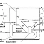
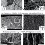
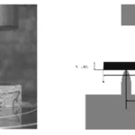
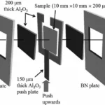
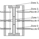
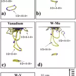
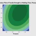
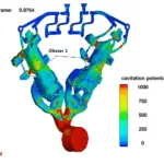
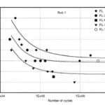
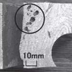
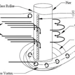
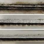
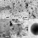


유체 흐름 및 열 전달 해석용 소프트웨어 패키지에는 여러 형태가 있습니다. 물리적 근사와 수치 해법의 기법이 패키지마다 크게 다르기 때문에 적절한 패키지를 선택하는 것은 매우 어렵습니다. 다음 설명에서는 열유동 시뮬레이션 소프트웨어를 선택할 때 고려해야 할 중요한 몇 가지를 소개합니다.
Software packages for fluid flow and heat transfer analysis come in many forms. These packages differ greatly in their physical approximations and numerical solution techniques, which makes the selection of a suitable package a challenging proposition. The following discussion covers some important items to consider when choosing flow simulation software.
유한 요소 또는 “body-fitted coordinates”를 채용하고 있는 수치해석 방법은 유체 영역의 기하학적 형상에 적합한 격자를 생성해야 합니다. 정확한 수치 근사치를 얻기 위해 허용 할 수 있는 요소 크기 및 형상에서 이러한 격자를 생성하는 것은 매우 중요한 작업입니다.
복잡한 경우에는 이와 같은 방법으로 격자를 생성하면 며칠 또는 몇 주가 걸릴 수 있습니다. 어떤 프로그램은 사각형의 격자 요소만을 사용함으로써 문제를 해결하려고 하지만, 그럴 경우에는 경계부분에 계단이 생기고 흐름과 열전달 특성이 달라지는 문제에 직면하게 됩니다.
FLOW-3D는 FAVOR™(면적율 / 부피 비율)법 을 사용하여 지오메트리의 특성을 원활하게 포함하므로써, 간단한 사각형 격자만으로도 두 문제를 해결할 수 있습니다. 또한, 간단하고 강력한 솔리드 모델러가 FLOW-3D 패키지에 기본 포함되어 있으며, CAD 프로그램에서 생성한 기하형상 데이터를 가져올 수 있습니다.
Solution methods that employ finite-element or “body-fitted coordinates” require the generation of a solution grid that conforms to the geometry of the flow region. It is a non-trivial task to generate these grids with acceptable element sizes and shapes for accurate numerical approximations. In complicated cases this type of grid generation may consume days or even weeks of effort. Some programs attemptto eliminate this generation problem by using only rectangular grid elements, but then they must contend with “stair-step” boundaries that alter flow and heat-transfer properties. FLOW-3D solves both problems by using easy-to-generate rectangular grids in which geometric features are smoothly embedded using the FAVOR™ (fractional area/volume) method. A simple and powerful solids modeler is packaged with FLOW-3D or users may import geometric data from a CAD program.
유체 운동량의 정확한 처리가 중요한 몇 가지 이유가 있습니다. 첫째, 이것은 복잡한 기하학적 형상에서 유체가 어떻게 흐르는지를 예측하는 유일한 방법입니다. 둘째, 액체에 의하여 걸린 동적인 힘(압력)은 운동량에서만 계산할 수 있습니다. 마지막으로, 열 에너지의 대류 수송을 계산하려면 다른 유체 입자 및 경계에 대한 개별 유체 입자의 상대적인 움직임을 정확하게 파악하는 것이 필요합니다. 이것은 운동량의 정확한 처리를 의미합니다. 운동량 보존을 대충 근사하기만 한 CFD 모델은 FLOW-3D에서는 사용되지 않습니다. 이러한 모델은 현실적인 유체 구성 및 온도 분포 예측에 사용할 수 없기 때문입니다.
An accurate treatment of fluid momentum is important for several reasons. First, it is the only way to predict how fluid will flow through complicated geometry. Second, the dynamic forces (i.e., pressures) exerted by the fluid can only be computed from momentum considerations. Finally, to compute the convective transport of thermal energy, it is necessary to have an accurate picture of how individual fluid particles move in relation to other fluid particles and confining boundaries. This implies an accurate treatment of momentum. Simplified flow models that only crudely approximate the conservation of momentum are not used in FLOW-3D because they cannot be used to predict realistic fluid configurations and temperature distributions.
액체와 고체 사이 (금속 주형 등)의 열전달은 경계면 면적의 정확한 추정이 필요합니다. 경계가 계단 모양으로 되어 있는 경우, 보통 이 면적이 크게 추정됩니다. 예를 들어, 실린더의 표면적은 약 27 %정도 크게 추정됩니다. FLOW-3D의 경우 정확한 경계면 면적은 FAVOR™법에 따라 FLOW-3D 전처리기에서 컨트롤 볼륨마다 자동으로 계산됩니다.
Heat transfer between a liquid and a solid (e.g., metal-to-mold) requires an accurate estimate of the interfacial area. Stair-step boundaries over-estimate this area; for example, the surface area of a cylinder would be over-estimated by a factor of 27%. Accurate interfacial areas are automatically computed by the FAVOR™ method for each control volume in the FLOW-3D pre-processor.
컨트롤 볼륨의 크기가 액체와 고체 사이에서 교환되는 열 비율과 양에 영향을 줄 수 있습니다. 이것은 열이 액체와 고체의 경계면을 포함하는 컨트롤 볼륨을 흐를 필요가 있기 때문입니다. FLOW-3D는 액체와 고체의 경계면에 걸쳐 열 전달률을 계산할 때 컨트롤 볼륨의 크기와 전도율이 고려됩니다.
The size of control volumes can influence the rate and amount of heat exchanged between a liquid and solid because heat must also flow in the control volumes containing the liquid/solid interface. In FLOW-3D control volume sizes and their conductivities are accounted for when computing heat transfer rates across liquid-solid interfaces.
비선형 방정식과 결합 방정식의 Implicit 방법은 반복 될 때마다 under-relaxation 특성을 갖는 반복적 해법이 필요합니다. 이 동작은 상황에 따라 심각한 오류 (또는 수렴 속도의 급격한 하락)가 발생할 수 있습니다. 예를 들어, 비율이 큰 컨트롤 볼륨을 사용하는 경우나, 실제로는 중요하지 않은 효과를 예상하고 암시적인 해법을 사용하는 경우 등입니다. FLOW-3D는 가능한 명시적인 수치해법이 사용되고 있습니다. 이것은 필요한 계산량이 적고, 수치 안정성의 요구 사항이 요구된 정밀도에 상응하기 때문입니다. 자세한 내용은 “암시적인 수치해법과 명시적인 수치해법“을 참조하십시오.
Implicit methods for nonlinear and coupled equations require iterative solution methods that have the character of an under-relaxation in each iteration. This behavior can cause significant errors (or very slow convergence) in some situations, for example, when using control volumes with large aspect ratios or when the implicitness is used in anticipation of an effect that is not actually significant. In FLOW-3D explicit numerical methods are used whenever possible because they require less computational effort, and their numerical stability requirements are equivalent to accuracy requirements. Read more in the Implicit vs. Explicit Numerical Methods article.
모든 크기의 타임 스텝 크기를 계산에 사용할 수 있는 암시적인 수치 기법은 CPU 시간을 줄이기 위해 많이 사용되는 방법입니다. 불행하게도, 이 방법은 대류 현상 해석에 대해 정확하지 않습니다. 암시적인 해법은 근사 방정식에 확산 효과를 도입함으로써 시간 단계의 독립성을 획득합니다. 수치 확산을 물리적 확산 (열전도 등)에 추가해도 확산율이 변경될 뿐이므로 심각한 문제가 되지 않을 수 있습니다. 그러나 수치 확산(발산)을 대류 과정에 추가하면 모델링 대상의 물리 현상의 특성은 완전히 다르게 됩니다. FLOW-3D는 시간의 정확한 근사치를 보장하기 위해 프로그램에 의해 time step이 자동으로 제어됩니다.
Implicit numerical techniques that allow arbitrarily large time-step sizes to be used in calculations are a popular way to reduce CPU time requirements. Unfortunately, these methods are not accurate for convective processes. Implicit methods gain their time-step independence by introducing diffusive effects into the approximating equations. The addition of numerical diffusion to physical diffusion, e.g., to heat conduction, may not cause a serious problem as it only modifies the diffusion rate. However, adding numerical diffusion to convective processes completely changes the character of the physical phenomena being modeled. In FLOW-3D time steps are automatically controlled by the program to ensure time-accurate approximations.
암시적으로 근사치를 사용하는 수치법은 하나 이상의 수렴 및 완화(이완)의 매개 변수를 선택해야 합니다. 이러한 매개 변수를 신중하게 선택하지 않으면 발산하거나 수렴에 시간이 걸리는 경우가 있습니다. FLOW-3D를 융합하는 매개 변수와 완화(이완) 매개 변수를 하나씩만 사용하여 두 매개 변수는 프로그램에 의해 동적으로 선택됩니다. 수치 해법을 제어하는 매개 변수를 사용자가 설정할 필요는 없습니다.
Numerical methods that use implicit approximations also require the selection of one or more convergence and relaxation parameters. Making poor choices for these parameters can lead to either divergences or slow convergence rates. Only one convergence and one relaxation parameter are used in FLOW-3D, and both parameters are dynamically selected by the program. Users are not required to set any parameters controlling the numerical solver.
액체와 기체의 경계면 (자유 표면 등)의 모델링에 사용되는 방법은 두 가지가 있습니다. 하나는 액체, 기체 두 영역의 흐름을 계산하고 경계면을 유체 밀도의 급격한 변화로 처리하는 방법입니다.
일반적으로 밀도의 불연속은 고차 수치 근사를 사용하여 모델링됩니다. 불행하게도 이 프로세스는 소수의 격자 셀에서 경계면이 평탄화되고, 이러한 경계면에 보통 존재하는 유체흐름의 접선 속도의 급격한 변화는 고려되지 않습니다.
기체가 계산 영역에 들어가는 액체로 대체되는 경우에는 이 방법에는 기체의 출구 포트 또는 출구 싱크도 보충 할 필요가 있습니다. 또한 이러한 방법은 일반적으로 유체의 비압축성를 충족하기 위해 더 많은 노력이 필요합니다. 이것이 발생하는 기체 영역에 거의 균일 한 압력 조정이 필요하며, 이를 통해 계산 수렴 시간이 소요되기 때문입니다.
FLOW-3D는 VOF (Volume-of-Fluid) 법 이라는 독창적인 방법이 사용되고 있습니다. 이것은 진정한 3 차원 경계면 추적 방식으로, 경계면을 3 차원 인터페이스로 추적하는 체계입니다. 또한 옵션의 표면 장력을 포함한 일반적인 접선 응력 경계 조건은 경계면에 적용됩니다. 기체 영역은 모델에 포함하도록 사용자가 요청하지 않는 한 계산되지 않습니다.
There are two methods used to model liquid-gas interfaces (i.e., free surfaces). One of these is to compute flow in both the liquid and gas regions and to treat the interface as a sharp change in fluid density. Typically, the density discontinuity is modeled using higher-order numerical approximations. Unfortunately, this treatment allows the interface to smooth out over a few grid cells and does not account for a corresponding sharp change in tangential flow velocity that generally exists at such interfaces. This technique must also be supplemented with escape ports or sinks for the gas if it is to be replaced by liquid entering a computational region. Further, such methods must typically work harder to satisfy the incompressibility of the fluids. This happens because gas regions must have nearly uniform pressure adjustments which tend to slow down the solution convergence rate. A different technique, the Volume-of-Fluid (VOF) method, is used in FLOW-3D. This is a true three-dimensional interface tracking scheme in which the interface is closely maintained as a step discontinuity. Moreover, normal and tangential stress boundary conditions, including optional surface tension forces, are applied at the interface. Gas regions are not computed unless the user requests these regions to be included in the model.
본 자료는 국내 사용자들의 편의를 위해 원문 번역을 해서 제공하기 때문에 일부 오역이 있을 수 있어서 원문과 함께 수록합니다. 자료를 이용하실 때 참고하시기 바랍니다.

본 자료는 전산유체역학(CFD)를 처음 접하시는 분들의 이해를 돕기 위해 작성되었습니다. 보통 열유동해석, 그냥 유동해석 또는 수치해석 중에서 유체를 다루는 해석이라고 쉽게 이해할 수 있겠습니다.
A general description of how to think about computational fluid dynamics (CFD) is given in the article, Simulating Fluid Flow with Free Surfaces. This article introduces the idea of reducing a simulation region into small volume control elements for which algebraic equations are constructed to describe the conservation of mass, momentum and energy exchanges with neighboring elements. Additionally, a simple method is introduced for a means of describing the motion of free fluid interfaces within the region of control elements.
전산 유체 역학 (CFD)의 개념에 대한 일반적인 설명은 자유 표면의 유동 시뮬레이션에 기술되어 있습니다. 이 절에서는 시뮬레이션 영역을 미소 체적 제어 요소로 세분화하는 아이디어를 적용하여, 볼륨 컨트롤 요소에 대해 질량 및 운동량 보존, 인접 요소와의 에너지 교환을 설명하는 대수 방정식이 구성됩니다. 또한 컨트롤 요소의 영역 내에서 자유롭게 유체 계면의 운동을 설명하는 간단한 방법도 설명되어 있습니다.
Also for beginners, the article, What you should know about CFD modeling when selecting a CFD software, contains brief summaries of a variety of issues that are important considerations for constructing numerical solutions to fluid dynamic problems. Many of these issues, such as meshing, geometry representation, implicit versus explicit numerical methods and relaxation/convergence parameters are explored in greater detail in the remaining articles in CFD-101.
또한 CFD를 처음 접하시는 분들을 위해, CFD 소프트웨어 선택시 전산 유체 역학 모델링에 대해 알아야 할 것에는 유체 역학 문제에서 수치 해석을 수행하기위한 중요하게 고려하는 다양한 이슈에 대한 내용도 포함되어 있습니다. 이러한 많은 이슈에는 메쉬, 기하 형상 표현, implicit 방법과 explicit 방법, relaxation/convergence 매개 변수 등이 있는데 본 CFD-101에 상세히 설명되어 있습니다.

본 자료는 국내 사용자들의 편의를 위해 원문 번역을 해서 제공하기 때문에 일부 오역이 있을 수 있어서 원문과 함께 수록합니다. 자료를 이용하실 때 참고하시기 바랍니다.
Advances in Nanotechnology
This article was contributed by Prof. Edward Furlani and his students from the University at Buffalo, SUNY.
Microfluidics와 nanofluidics는 나노와 나노사이의 기능을 가진 재료와 시스템을 통한 유체 흐름의 과학과 기술을 포함하는 분야입니다. 최근 몇 년 사이에 이 분야의 연구는 재료 개발과 시스템의 급속한 발전된 유체공정의 독특한 이점으로 증가해 왔습니다. Microfluidic 및 nanofluidic 시스템은 화학 반응, 유체 가열, 혼합 및 감지와 같은 순차적 또는 다중화된 공정을 포함할 수 있는 응용 분야에서 마이크로 사이즈의 유체 유동은 매우 효율적이고 반복 가능하며 신속한 처리를 가능하게 합니다. 풀 라니 (Furlani) 교수 그룹의 연구는 새로운 공정 및 장치 개발에 대한 모델링 및 시뮬레이션을 보여줍니다. 이 연구의 대부분은 뉴턴 및 비 뉴턴 유체, 열 전달, 상변화 분석, 자유표면 및 다상분석, 유체와 관련된 유체 현상을 연구하기 위해 최첨단 전산 유체역학을 강조합니다. 매체 상호작용, 다공성 매체를 통한 유동, 완전히 결합된 유체구조 및 입자, 유체 상호작용에 대해 콜로이드. 국제 나노 기술 학술 대회에서 3 편의 논문이 발표될 예정입니다. 2014년 6월 15일부터 18 일까지 워싱턴 DC의 Gaylord National Hotel 및 Convention Center에서 개최됩니다. 이들은 버팔로 대학교 (University at Buffalo)에서 진행되는 획기적인 결과를 선보입니다. 여기에서는 이러한 작품의 미리 보기와 FLOW-3D로 생성된 시뮬레이션 결과 중 일부를 제시합니다.
Analysis of Stem Cell Culture Performance in a Microcarrier Bioreactor System
Koushik Ponnuru1, Jincheng Wu1, Preeti Ashok1, Emmanuel S. Tzanakakis1,3,4,5,6 and Edward P. Furlani1,2
1Dept. of Chemical and Biological Engineering, 2 Dept. of Electrical Engineering, 3Dept. of Biomedical Engineering, 4New York State Center of Excellence in Bioinformatics and Life Sciences, 5Western New York Stem Cell Culture and Analysis Center, 6Genetics, Genomics and Bioinformatics, University at Buffalo, SUNY

(left) Shear stress distribution along with velocity vectors in a cross sectional plane of the bioreactor running at 60 rpm; (right) Kolmogorov length scale distribution at the same plane under the same conditions.
CFD 기반 시뮬레이션과 실험결과의 조합으로 교반 탱크의 마이크로 캐리어 생물 반응기 시스템에서 세포 배양에 대한 난류 전단응력의 영향에 대한 분석을 제시합니다. Corning’s bench-scale spinner flask의 3D 계산 모델은 최첨단 CFD 소프트웨어 인 FLOW-3D를 사용하여 제작되었습니다. 임펠러 속도, 배양액 및 입자 크기와 같은 매개변수가 마이크로 캐리어 입자에 작용되는 전단응력에 미치는 영향을 CFD 분석을 사용하여 연구하였습니다. 이것은 세포가 겪는 정확한 전단 조건을 예측하고 세포의 손상을 방지하는 최적의 작동조건을 확인하는데 사용됩니다. 또한, 다원능 마커 Oct4, Sox2 및 Nanog를 운반하는 세포의 비율을 세포 계측법 및 정량적 PCR을 사용하여 측정함으로써 hPSCs의 다능성 전단효과를 연구합니다.
Numerical Analysis of Fully-Coupled Particle-Fluid Transport and Free-Flow Magnetophoretic Sorting in Microfluidic Systems
Chenxu Liu1, Xiaozheng Xue1 and Edward P. Furlani 1,2
1Dept. of Chemical and Biological Engineering, 2Dept. of Electrical Engineering, University at Buffalo, SUNY
Magnetic nanoparticle chaining and rotating following an external field and causing the mixing of two different molecular concentrations.
Magnetic 입자는 생체 의학 및 임상 진단 응용을 위해 생체 재료를 선택적으로 분리 및 분류하는 마이크로 유체시스템에 점점 더 많이 사용되고 있습니다. 그러한 시스템의 합리적인 설계에 사용될 수 있는 전산모델이 도입되었습니다. 이 모델은 자기 및 유체 역학적 힘, 완전 결합 입자 – 유체 상호 작용 및 입자의 자기 조립을 유도하는 자기 쌍극자와 쌍극자의 상호 작용을 비롯한 입자 수송에 대한 지배적 메커니즘을 고려합니다. 응용 프로그램을 통해 연속흐름 분리시스템 및 회전 조립 체인을 기반으로 하는 미세 유체 혼합프로세스로 시연됩니다.
Numerical Analysis of Laser Induced Photothermal Effects using Colloidal Plasmonic Nanostructures
Ioannis H. Karampelas1, Young Hwa Kim2 and Edward P. Furlani 1,2
1Dept. of Chemical and Biological Engineering, 2 Dept. of Electrical Engineering, University at Buffalo, SUNY

Photothermal heat cycle of a nanocage (a=50nm, t=5nm) (perspective 1/8 view): plot of nanocage temperature vs. time, pulse duration indicated by the red arrow and dashed line and inset plots showing various phases of the thermo -fluidic cycle: (a) nanobubble formation, (b) nanobubble (maximum size), (c) nanobubble collapse, (d) cooling.
Colloidal 귀금속 (plasmonic) 나노 구조는 나노 입자 합성에서부터 바이오 이미징 (bioimaging), 의학 요법 (medical therapy)에 이르기까지 다양한 광열 (photothermal) 분야에서 점점 더 많이 사용되고 있습니다. 많은 응용분야에서, 펄스 레이저는 plasmonic 공진 주파수에서 나노 구조를 사용하며, 이는 광자의 흡수 및 고도로 국부화된 파장필드의 향상을 가져옵니다. 원격 소스로부터 효율적인 나노 스케일 가열하는 것 외에도, 합성동안 나노 입자의 구조를 조정함으로써 근적외선 스펙트럼을 통한 공진 가열파장을 조정할 수 있습니다. 우리 그룹은 nanosecond-pulsed, laser-heated colloidal metallic nanoparticles 및 열 유체 거동을 예측하는 전산모델을 개발했습니다. 이 모델은 플라즈몬 공명, 입자에서 주변 유체로의 열 전달 및 균일한 기포 핵 형성을 유도하는 유체의 위상변화에서 나노 입자 내의 에너지 전환을 시뮬레이션 하는데 사용되었습니다. nanorods, nanotori, nanorings 및 nanocages 등 다양한 nanoparticle 형상이 연구되었습니다. 이 분석은 레이저 강도, 입사 파장, 편광, 펄스 지속 시간 및 나노 입자의 방향 및 모양과 같은 공정 매개 변수가 광열 공정을 최적화하도록 조정될 수 있음을 보여줍니다. Plasmonic nanoparticles는 악성 조직의 약물 치료, 약물 전달 및 생체치료에 사용됩니다.

Kodak Develops New Printhead Design in 1/3rd the Time
Eastman Kodak Company가 잉크젯 프린팅 시장에 진입했을 때 회사는 낭비 할 시간이 없었습니다. Kodak은 프리미엄 안료-기반 잉크를 사용하여 잉크 카트리지를 교체하지 않고 프린트 헤드를 프린터에 통합하여 수명이 오래 지속되고 잉크 비용을 크게 절감하는 생생한 컬러의 사진 인쇄물을 제공함으로써 비즈니스 진출을 계획했습니다. 이러한 발전으로 완전히 새로운 프린트 헤드 개발이 필요했습니다. 업계 경험에 따르면 완전히 새로운 잉크젯 프린터 기술을 개발하는데 보통 8-10 년이 걸렸습니다. Kodak 연구원은 프로젝트의 시간 제약조건을 충족시키기 위해 매우 정확한 시뮬레이션 소프트웨어와 설계를 최적화하는 체계적인 방법이 모두 필요하다는 것을 알고 있었습니다. FLOW-3D 및 D-optimal 설계 실험 (DOE)을 사용하여 Kodak 연구원은 불과 3 년 만에 작업을 완료했습니다.

KODAK EASYSHARE 5500 all-in-one printer
Innovative Ink Leads to New Printer Line
Kodak의 EASYSHARE 프린터 라인을 형성하는 핵심 혁신은 염료-기반 잉크와 동일한 수준의 광택을 제공하지만 훨씬 오래 지속되는 안료-기반 잉크의 개발이었습니다. Kodak 엔지니어는 이 새로운 잉크를 용지 및 기타 용지에 정확하게 공급하면서 기존의 프린트 헤드보다 훨씬 긴 수명을 제공 할 수 있는 프린트 헤드를 개발할 필요가 있었습니다.
FLOW-3D는 우수한 경향 예측뿐만 아니라 시각적 관찰도 우수한 질적인 결과를 제공합니다. 마찬가지로 소프트웨어는 설계 민감도를 정확하게 예측합니다. 결과적으로, FLOW-3D는 Kodak의 첨단 연구 및 개발 활동을 지원하는 귀중한 통찰력을 제공했습니다.
– Christopher Delametter, Senior Research Scientist, Eastman Kodak Company
Simulation Spotlight: Homogeneous Bubble Model

Homogenous Thermal Bubble model
Kodak 엔지니어는 유체 및 열 흐름에 증기 기포의 형성을 연결하는 균일한 버블 모델을 통합하는 FLOW-3D를 사용하여 프린트 헤드 작동을 정확하게 시뮬레이션 했습니다. thin-film stack내의 열원은 고체 구조내에서의 전도 및 유체 / 고체 계면에서의 열전달에 의해 잉크로 운반됩니다. 유체에서 과열 온도에 이르면 증기 거품이 폭발적으로 형성됩니다. 기포는 균질 한 압력과 온도를 갖는 것으로 가정되며, 그 동역학은 증기에 대한 Clapeyron 방정식에 의해 지배된다. 기포 / 액체 계면에서의 질량 및 열교환은 기포가 팽창함에 따라 계속되고, 질량 유속은 운동 이론에 따라 결정됩니다. 표면장력과 점성영역도 시뮬레이션에 포함됩니다. 모델에서의 힘과 플럭스의 적절한 구현은 자유 표면의 정확한 추적에 달려 있는데, 이는 TruVOF 방법론을 사용하여 달성되며 계산의 중요한 부분입니다.
Design of Experiments
DOE를 사용하여 CFD를 구동함으로써 Kodak 연구원은 경쟁사보다 훨씬 짧은 시간에 프린트 헤드 디자인을 최적화 할 수 있었습니다. 시뮬레이션의 장점은 연구원이 색상 중 하나에 대해보다 최적의 잉크 배합을 발견했을 때 나타나며 프로젝트 후반부에 분명했습니다. 잉크는 이러한 장점을 이용하기 위해 신속하게 재구성되었습니다. 그러나 프린트 헤드를 1 년 이상 재설계해야 할 필요가 있을까요? 다행히 Kodak 연구원은 이미 잉크 특성에 대한 민감성 연구를 수행했으므로 단일 시뮬레이션을 추가하지 않고도 기존의 프린트 헤드 설계가 제대로 작동 할 것이라고 신속하게 판단했습니다. 따라서 EASYSHARE 프린터 제품군은 프로젝트가 시작된 지 불과 3 년 만에 출시되었으며, 일반적으로 새로운 잉크젯 기술을 시장에 출시하는 데 소요되는 시간은 약 3 분의 1입니다.
Comparison between physical experiments and simulation—Early experimental device configuration.
Learn more about the power and versatility of modeling microfluidic applications with FLOW-3D >

Investigation of Mould Leakages in a Gravity Casting
This article was contributed by Gabriele Taricco of CM Taricco and Stefano Mascetti of XC Engineering.

Metal leakages in the original gravity casting mould
몰드 설계는 유체 역학과 금속 응고 패턴뿐만 아니라 주형 자체에서 발생할 수 있는 문제와 응력에 대한 반응을 고려해야 하는 매우 복잡한 작업입니다. 이탈리아에 본사를 둔 주형 제작 업체인 CMTaricco 사는 최근에 새로운 주형 중 하나의 하부에서 금속 누출 문제에 직면했습니다. 주형 누출의 원인은 처음에는 분명하지 않았으며 몇 번의 공정 주기 후에만 나타났습니다. 제작 일정에 차질이 생기고 부품 주조 비용이 급격히 증가하기 때문에 문제가 중요한 것은 분명했습니다.
Investigation of an idea
공정 자체는 주입과 오버플로우 설계인 중력 주조 방식이었기 때문에 유체 역학 부분에서는 문제가 발생할 수 없었습니다. GabrieleTaricco (CMTaricco의 소유주)의 가설은 금속 누출이 주형의 열 손실의 설계 불량에서 기인하여 균일하지 않은 분포를 초래한다는 것이었습니다. 변형률과 그에 따라 주형 바닥에서 크고 원하지 않는 변형이 순환하면서 금속이 유출될 수 있는 중요한 영역의 개방까지 주기적으로 시행되었습니다. 이를 확인하고 문제에 대한 신속한 해결책을 찾기 위해 FLOW-3D시뮬레이션을 실행하여 주형이 가열될 때 발생하는 현상을 정확하게 파악했습니다.

Schematic of a critical area where metal was flowing out of the mould
A careful setup, to achieve a fast resolution of the issue
문제의 원인은 신속하게 파악할 수 있어야 했기 때문에 최신 Flow-3D기능을 모두 활용하여 정확한 설정이 필요했습니다. 특히, 채택된 meshing기법은 전통적인 설정과 거의 동일한 정확도를 유지하면서 전산 셀의 수를 크게 줄이는데 매우 도움이 되었습니다. 빠른 시뮬레이션으로 주형 세척에 사용된 첫 번째 방법은 주형 내부의 얇은 캐비티를 직교 축과 정렬하기 위해 주형을 수직 축 주위로 회전시키는 것이었습니다.

Rotating the mould around the vertical axis in order to align the inner thin cavity of the mould
두 번째 트릭은 내부 공동 (얇은 벽)에 new conformal mesh기능을 사용하는 한편 전체 도메인에 대해 기존의 더 큰 메쉬 블록을 유지하는 것 이었습니다. The conformal mesh는 open volume과 일치하고, 작은 간극을 갖는 cavity로 제한됩니다.
A global view of the mould with cores and its alignment with the mesh blocks
마지막으로, 외부 공간을 주형에 제한하기 위해(현재 구두 상자 모양이 되고, 20도 회전하며, 모델 축과 정렬상태) 일부’ 도메인제거’ 요소가 사용되었습니다.즉, FLOW-3D의 내부 솔리드 모델을 통해 직접 연결됩니다

Domain removing components (yellow) were used to limit the space externally to the mould.
나머지 설정은 소프트웨어의 권장 기본값 대부분을 이용하여 기존 체계를 따랐습니다. 이러한 기능과 FLOW-3D의 새로운 하위 도메인 분해 기능 덕분에 설계된 9 000 000 셀을 유체 하위 도메인의 경우에만 1 840 000 셀로, 고체 서브 도메인의 경우 2 430 000 셀로 줄이는 것이 가능했습니다.
The analysis
주입 시뮬레이션 후, 양호한 주입 패턴을 보장하기 위해 시뮬레이션의 초점이 열 다이 사이클링 분석으로 리디렉션 되었습니다. 이 경우 설정은 일반 데스크 톱 컴퓨터에서 10개의 생산 사이클을 재현하는 데 1시간이면 간단하고 빠릅니다(i7930 K, 상업적 가치 1500달러). 그 결과 CM의 초기 가설이 확인되었습니다. FlowSight를 사용하여 단일 이미지에서 여러 시점과 횡단면에서 온도 필드를 관찰한 결과 온도가 d라는 것이 분명했습니다. 주형의 침입은 예상되는 변형과 금속 누출을 쉽게 유발할 수 있습니다.
Simulation of the mould’s temperature during the die cyclings
Further analysis with the Fluid-Structure Interaction module
일단 문제가 확인되고 기술 요원이 향상된 금형 설계를 시작하면 CM Taricco는 다이 상의 응력 및 변형에 대한 FEM 해석을 실행하는 최종 확인을 원했습니다. 이 분석을 수행하기 위해 XC Engineering Srl은 CM이 계산을 설정하고 수행하는 것을 도왔습니다. 분석의 결과는 정확히 CM이 생각하고 있는 것을 보여주었습니다. FLOW-3D는 붓기가 거의 걸리지 않은 금형에서 발견 된 실제 변형과 동일한 위치와 크기를 극도의 정확도로 재현 할 수 있었습니다. 이것은 CM에 대한 좋은 소식이었으며, 실제 주조 조건을 기반으로 실제 금형 변형을 예측하기 위해 설계 단계에서 FSI 모듈을 사용하는 추가 권장 사항을 시행했습니다.
Deformation of the mould during the die cyclings, simulated using the Fluid Structure Interaction model. Deformations are amplified x20.
Conclusion
해석결과, CM직원은 CFD솔루션의 온도영역에 대한 모든정보를 사용하여 최적화된 새로운 주형을 설계할 수 있었습니다. 새로운 주형은 열 에너지를 보다 효율적인 방법으로 방출할 수 있었으며 주조물은 수 십번의 공정 주기 후에도 금속 누출의 영향을 받지 않았습니다.

The cast part after mould optimization. No critical leak defects are present.


FLOW-3D를 활용한 항공우주 분야의 주요한 사례는 슬로싱(sloshing)에 의한 유체의 유동 영향을 평가하는 해석과 기상(gas phase) 유체에 대한 아음속 및 초음속 유동 해석으로 크게 나눌 수 있다.
슬로싱 유동 해석
슬로싱(sloshing)은 탱크 내부에 적재된 유체가 외부의 가진에 의하여 발생하는 유동 현상이다. 이는 흔히 볼 수 있는 컵 내부 물의 유동부터 항공기 및 선박, 우주선의 연료탱크 내부 유동까지 다양한 분야에서 나타나는 유동 현상이다. 이러한 슬로싱의 영향은 유체와 탱크의 상호 작용으로 충격 압력이 발생하게 되며, 슬로싱에 의한 충격이 계속 반복되면서 탱크 내부에 피로로 인한 균열(crack)로 탱크의 파괴를 초래할 수 있다.
그 동안 슬로싱 현상을 연구하기 위해 많은 실험과 수치 해석이 수행되어 왔다. 우주 로켓의 연료 탱크와 관련된 슬로싱 유동에 대하여 많은 연구들이 진행된 바 있고, 1980년대 이후에는 LNG 수송선이 증가하면서 선박 내의 슬로싱 유동에 대한 많은 연구가 진행되었다. 실험적인 연구 방법은 많은 실험비용과 시간 및 장비가 요구되기 때문에 이를 대치하기 위하여 많은 수치해석이 시도되어 왔다.
Faltinsen은 진동하는 2차원 슬로싱 문제에 대하여 수치해석을 하였고, Wu et al은 유한 요소 법을 이용하여 3차원 수치해석을 시도하였다. 자유표면 문제에 대해서 수치적 확산을 줄이기 위하여 Takewaki and Yabe에 의하여 CIP(constrained interpolation profile) 기법이 개발 되었고, Yang and Kim은 2009년 물과 공기의 다상 문제를 해석하는 CCUP(Cip-combined and unified procedure) 기법을 이용하여 슬로싱 문제에 대한 수치해석을 수행하였다. 3차원 열유동 해석 프로그램인 FLOW-3D를 이용한 해석은 2006년 Lee et el.에 의하여 수행된 바 있다.
현재까지 슬로싱 현상을 해석하기 위하여 많은 수치기법들이 개발되고 이용되어 왔지만, 슬로싱의 특성상 강한 비선형 자유표면에 대한 정확한 해석에 어려움이 남아있다. 이러한 비선형 슬로싱 문제에 대하여 FLOW-3D를 이용하여 수치해석하였고, 앞서 진행되었던 실험 및 수치해석 연구 결과의 압력 및 자유표면의 형상을 비교하였다.
해석결과와 실험을 비교하기 위하여 해석을 진행하였으며, 탱크의 형상을 <그림 1>에 나타냈다. 이 모델에 대한 실험은 1991년 히타치(Hitachi) 조선 연구소와 대우조선해양에서 수행한 바 있다.

그림 1. 스키매틱 다이어그램(schematic diagram) without baffles, fluid filling 50%
초기에 탱크는 정지상태로부터, 다음 식과 같이 좌우로 병진운동을 하게 된다.
다운로드 : [ 5회_201805_analysis_flow3d ]
작성자 | 민창원_에스티아이C&D 솔루션 사업부 과장, 조애령_에스티아이C&D 솔루션 사업부 차장
이메일 | flow3d@stikorea.co.kr
홈페이지 | www.flow3d.co.kr
출처 : CAD&Graphics 2018년 05월호


(주)에스티아이씨앤디에서는 고객이 수치해석을 직접 수행하고 싶지만 경험이 없거나, 시간이 없어서 용역을 통해 수치해석 결과를 얻고자 하는 경우 전문 엔지니어를 통해 CFD 컨설팅 서비스를 제공합니다. 귀하께서 당면하고 있는 연구프로젝트를 최소의 비용으로, 최적의 해결방안을 찾을 수 있도록 지원합니다.
상담에는 비용은 전혀 들지 않습니다.
CFD는 엔지니어가 공기, 물 또는 모든 유체와의 상호 작용을 이해할 수 있게 하는 매우 효과적인 기술로 대부분의 유동현상에 해답을 제시 할 수있는 막대한 잠재력을 가지고 있습니다.
다양한 유체 흐름 현상이나 온도 및 열전달 분석 등 필요한 시나리오에 대한 맞춤 솔루션을 제공합니다.
당사에는 20년 이상 수치해석 연구에 전념하고 있는 전문 연구인력과 다양한 기술적 경험과 전문 시뮬레이션 기술을 제공하는 숙련된 기술컨설팅팀이 준비되어 있습니다.
귀하의 프로젝트 성공 가능성을 기술시연을 통해 제공 할 수 있습니다.
프로그램 소개나 자문이 필요하신 분들은 언제든지 아래 연락처로 문의하시기 바랍니다.


HVAC(난방, 냉방 및 환기)시스템 엔지니어가 고려해야 하는 최적 설계 배치에 대한 검토를 수행
발전소의 경우 대형(길이 90m, 너비 33m, 높이 26m)건물로 변압기, 전력선, 조명 등 열 발생 장비를 갖추고 있어서 여러가지 시설물의 상황을 고려할 수 있음
건물 내 공기를 올바르게 분배하고 적절한 쾌적한 온도를 확보하기 위해 건물 구조와 흡입그 크기 등의 검토 가능
고객이 의뢰하는 컨설팅 내용은 경쟁에 민감한 정보를 포함할 수 있기 때문에 (주)에스티아이씨앤디에서는 고객의 기밀정보를 보호하기 위한 엄격한 관리절차와 이행을 보장합니다.
고객의 기밀정보는 절대 외부에 누설되지 않습니다.
수치해석 용역 또는 기술컨설팅, Custom 개발이 필요하시면 언제든지 아래 연락처로 연락주시기 바랍니다.
연락처 : 02-2026-0455
이메일 : flow3d@stikorea.co.kr

□ 공공기관
□ 기계전자분야
□ 건설분야
□ 엔지니어링 분야


컨설팅 절차
컨설팅 분야

HVAC(난방, 냉방 및 환기)시스템 엔지니어가 고려해야 하는 최적 설계 배치에 대한 검토를 수행
발전소의 경우 대형(길이 90m, 너비 33m, 높이 26m)건물로 변압기, 전력선, 조명 등 열 발생 장비를 갖추고 있어서 여러가지 시설물의 상황을 고려할 수 있음
건물 내 공기를 올바르게 분배하고 적절한 쾌적한 온도를 확보하기 위해 건물 구조와 흡입그 크기 등의 검토 가능

Introduction and Problem Statement
신속, 반복, 작은 물방울의 생성 및 증착, 작은 형상의 프린팅 또는 패터닝 (예 : l = 10-3-1 mm), 스프레이로 균일한 두께의 박막 형성은 다양한 산업에 매우 중요합니다(1-5). 액체 이동과 액적 형성 / 증착 공정은 복잡한 자유 표면 흐름, 자연적인 모세관운동 형성, thinning, pinch-off를 수반한다 (1-5). 단순한 뉴턴 및 비탄성 유체에 대해 액적 생성 및 액적 이동을 분석하기위한 실험적, 이론적 및 1 차원 시뮬레이션 연구가 진행되었지만 프린팅 또는 패터닝에 대한 기계론적인 이해는 여전히 과제로 남아 있습니다. 현재의 계산에 대한 주된 목표는 뉴턴 유체의 pinch-off에 대한 기계론적 이해를 얻기 위해 FLOW-3D에 내장된 VOF(volume-of-fluid) 접근법으로 시험하는 것입니다. 전산해석은 모세관, 관성, 점성 응력의 복잡한 상호 작용을 포착하여 자기유사 모세관의 thinning and pinch-off를 결정합니다. 뉴턴 유체의 물방울 형성 및 분리현상은 전산해석으로부터 얻어진 자기유사 모세관현상 이론, 보편적인 축소화 기법인 1D 시뮬레이션 (1-7)과 실험 (1, 2, 8-12)을 이용하여 설명될 수 있음을 보여준다. 이러한 우리가 진행한 원형흐름 시뮬레이션은 유한한 시간의 비선형 역학, 위성 낙하현상, 복잡한 형상의 프린팅과 같이 어려운 전산해석의 기반이 될 것 입니다.
표면 장력 및 중력 모델을 적용한 FLOW-3D 에서 균일한 메쉬 크기를 사용하여 노즐에서 드롭 형성 및 분리에 대한 시뮬레이션을 수행하였습니다. 유한 체적의 유체를 떨어뜨리거나 분리하는 일은 물방울의 성장과 드롭, 노즐에 연결되는 모세관 현상, 관성, 점도 및 중력에 대한 상호 작용을 수반합니다. 시뮬레이션에서 스테인레스 강 노즐 ( 

| Fluid Property | Fluid 1 | Fluid 2 | Fluid 3 | Fluid 4 | Fluid 5 |
| Viscosity [Pa · s] | 0.05 | 0.02 | 0.01 | 0.0075 | 0.005 |
| Surface Tension [mN / m] | 68 | 68 | 68 | 68 | 68 |
| Density [g / cm 3 ] | 1 | 1 | 1 | 1 | 1 |
| Ohnesorge Number | 0.21 | 0.08 | 0.04 | 0.03 | 0.021 |
| Fluid Property | Fluid 6 | Fluid 7 | Fluid 8 | Fluid 9 |
| Viscosity [Pa · s] | 1.5 | 0.8 | 0.5 | 0.25 |
| Surface Tension [mN / m ] | 68 | 68 | 68 | 68 |
| Density [g / cm 3 ] | 1 | 1 | 1 | 1 |
| Ohnesorge Number | 6.24 | 3.33 | 2.08 | 1.04 |
고점도 유체 (표 2의 유체 8) 가 노즐에서 떨어지는 것을 시뮬레이션 합니다. 색상변수는 속도크기 (단위 : cm / s) 이며 속도 벡터가 표시됩니다.
Discussion of the Simulation Results
드롭 형성 및 분리는 표1과 표2에 열거 된 유체에 대해 FLOW-3D 를 사용하여 시뮬레이션 하였고, 시간 경과에 따른 necking 모양, 반경을 분석하였습니다. 물방울의 necking 모양과 저점도에서의 necking에 대한 역학(그림 1 참조)은 실험, 흐름 이론, 1D 시뮬레이션, 자기유사 관성에 대한 모세현상의 특성을 나타냅니다 (1, 2, 6, 7, 13) :
(1)
여기서 R (t)가 necking의 순간 반경이고, R0는 노즐의 외부반경이며, 

(2)
모세관 속도(표면 장력과 점도의 비)의 측정 값은 McKinley와 Tripathi (8)에 의해 Capillary Break-Up Extensional Rheometer (CaBER)라고 불리는 상업적으로 이용 가능한 장비를 사용하여 얻은 값과 모세관 속도는 공칭 표면 장력과 점도를 사용하여 계산됩니다.
FLOW-3D 는 물방울의 necking부분을 속도 벡터로 시각화하여 유체의 흐름을 나타낼 수 있습니다. 또한, 이는 그림 1과 같이 전단, 확장을 겪은 후 얇아지는 물방울이 흐르는 과정의 순간을 결정할 수 있는 가능성을 줍니다. 추가로, 낮은 점도의 뉴턴유체는 높은 점도의 뉴턴 유체에 비해 질적으로 다른 거동을 보여준다(그림 2참조). 낮은 점도의 뉴턴 유체에 대한 necking 프로파일은 이론(6,13)에 따라 자기 유사성이 됩니다.
우리의 예비결과는 FLOW-3D 기반의 전산해석이 액적 형성과 탈착의 기초가 되는 프로토타입의 자유 표면흐름을 시뮬레이션하는데 사용될 수 있음을 보여줍니다 . 시뮬레이션된 반경변화 프로파일이 실험적으로 관찰된 높은 유체 및 이론적으로 예측된 유체인 스케일링 법칙 및 pinch-off dynamics과 일치하는 것을 발견하였습니다.
자주 사용되는 1D 또는 2D 모델과 달리 FLOW-3D 는 기본 응력 및 확장 유동장 (균일도 및 크기)의 강도와 얇은 액체 필라멘트 내 흐름에 대한 시각화를 나타낼 수 있습니다(그림1과 2 참조). 확장 유동장과 연관된 흐름 방향 속도 구배는 모세관현상이 나타나는 물방울의 얇은 부분 내에서 발생합니다. 유동학적으로 복잡한 유체에서 non Newtonian shear 및 신장, 점도뿐만 아니라 그외의 탄성 응력이 nonlinear pinch-off dynamics을 급격하게 변화시킵니다(2, 10-12). 우리는 현재 점탄성과 non-Newtonian 유동학을 사용하여 FLow-3D에 복합 유체의 처리 성능평가를 위한 강력한 연산 프로토콜을 개발하고 있습니다.

FLOW-3D의 열 응력 진화 (TSE) 모델은 모델링 할 수있는 주조 공정의 범위를 확장합니다. FSI / TSE 모델은 주변 유체의 압력 력, 온도 구배 및 지정된 구속 조건에 대한 응답으로 솔리드 및 응고 부품의 모델 응력 및 변형에 대한 유한 요소 접근법을 사용하여 유체와 솔리드 간의 완전 결합 상호 작용을 설명합니다.
불균일 냉각으로 인해 응고 과정에서 열 응력이 발생합니다. 이러한 응력은 주형 벽의 수축과 주조 모양의 불규칙성에 영향을받습니다.
위의 시뮬레이션은 고형 알루미늄 V6 엔진 블록의 Von Mises 응력을 보여줍니다. 이 블록은 강철 다이 내에서 주조 된 알루미늄 A380 합금으로 구성됩니다. 알루미늄의 주입 온도는 527 ° C 였고 초기 다이 온도는 125 ° C였다. 부품을 다이에서 60 초 동안 냉각시킨 후 다이를 열고 주변 조건 (125 ° C)에서 부품을 9 분 동안 계속 냉각시켜 총 10 분의 시뮬레이션 시간을 가졌다. 보여진 폰 미제스 응력은 부품 내부의 전단 응력의 크기를 측정 한 것으로, 파열이 가장 많이 발생하는 부위를 나타냅니다. 응력은 금형과 응고 금속에서 동시에 계산 될 수 있습니다. 메싱은 FLOW-3D의 구조화 된 메쉬를 초기 템플릿으로 사용하여 자동으로 수행 할 수 있습니다. 사용자는 중첩 또는 링크 된 메쉬 블록을 생성하고 V11.0의 새로운 준수 메쉬 기능을 사용하여 메쉬의 로컬 해상도를 제어 할 수 있습니다. 또는 Exodus-II 형식의 타사 메쉬 생성 소프트웨어에서 Finite Element 메쉬를 가져 오는 옵션이 있습니다.
아래 그림은 강철 다이 내에 알루미늄 A380 합금 주물로 구성된 알루미늄 커버입니다. 주입 온도는 654 ℃이고 초기 다이 온도는 240 ℃이다. 부품은 6 초 동안 다이 내에서 냉각되어 부품이 완전히 고화되었다 (러너 시스템 제외). 그런 다음 다이를 열고 부품을 주변 조건 (25 ° C)에서 10 초 더 냉각시켰다. 러너 시스템을 제거한 후 주위 조건에서 10 초간 더 냉각시켰다. 여기에 표시된 일반 변위는 가장 큰 변형 영역을 강조하기 위해 30 번 확대 된 부품 표면의 동작을 나타냅니다.

FLOW-3D v11의 새로운 기능은 인접한 유체 구조 상호 작용 (FSI) 구성 요소 및 / 또는 열 응력 진화 (TSE) 응고 유체 영역 사이의 탄성 응력을 허용하는 기존의 유한 요소 역학 해석법으로의 업그레이드입니다. 결합. 이 새로운 기능은 복잡하고 변형이 심한 다중 재료 부품 (예 : 몰드에서 금속 주 조용 응고 또는 바이메탈 게이지)의 열 응력과 변형을 시뮬레이션하고 연결된 유압에서 힘을 시뮬레이션하는 것을 포함하여 풍부한 모델링 가능성을 열어줍니다. 레이디 얼 게이트 및 파이프 라인 지원 시스템과 같은
모델에는 복잡한 프로세스를 효율적으로 계산할 수있는 몇 가지 옵션이 있습니다.
이 옵션은 인접한 FSI 구성 요소가 스트레스를 교환하지 않는 단순화 된 사례를 나타냅니다. 이것은 계산 상 효율적이며 구성 요소 간의 응력 상호 작용이 중요하지 않은 시나리오에 적합합니다.
전체 커플 링 옵션은 함께 융합되었지만 재료 특성이 다른 이웃 FSI 구성 요소를 모델링하기위한 것입니다. 두 구성 요소는 서로 떨어져서 당기거나 서로 밀어 낼 수 없지만 인터페이스의 응력은 구성 요소간에 전송됩니다. 이는 바이메탈 스트립과 같은 접합 구조를 모델링하는 데 이상적입니다.
부분 커플 링 옵션은 인접한 FSI 구성 요소가 마찰 및 수직력을 통해 상호 작용하지만 분리 될 수있는 일반적인 문제를 모델링하기위한 것입니다. 이 옵션은 FSI 구성 요소와 TSE 응고 유체 영역을 결합하는 데 사용할 수 있으므로 다이에서 냉각되는 부품과 주조 부품에 대한 열 응력의 영향을 조사하는 데 이상적입니다.
모델의 새로운 기능을보다 자세히 보여주기 위해 두 가지 시뮬레이션이 제공됩니다. 첫 번째 상황은 전체 커플 링 옵션을 사용하여 시간에 따라 변화하는 온도에 따라 바이메탈 스트립 벤딩을 모델링하는 반면 두 번째 예는 다이 커플 링에서 V6 엔진 블록의 응고 중 열 응력을 보는 부분 커플 링 모델의 사용을 보여줍니다 .
전체 커플 링 옵션의 가장 단순한 예 중 하나는 온도 구배에 따른 바이메탈 스트립의 움직임입니다. 이러한 스트립은 두 개의 금속이 온도 변화에 반응하여 동일한 속도로 팽창하지 않기 때문에 열 스위치 및 굴곡에서 일반적으로 사용됩니다. 시뮬레이션에서 모델링 된 바이메탈 스트립은 그림 1에서와 같이 동일 치수의 구리 스트립에 접합 된 길이 15cm, 두께 0.5cm의 강철 스트립으로 구성된 캔틸레버 빔입니다.

그림 1 : 예제 시뮬레이션에 사용 된 바이메탈 스트립의 개략도. 검은 색 화살표는 처짐이 탐지 된 곳을 나타냅니다. 긍정적 인 처짐은 상향이다.
이어서, 스트립을 온도가 70 초 이상 균일하게 변화하는 환경에 두었다. 그림 2는 시뮬레이션을위한 스트립 팁의 편향과 시간 경과에 따른 다양한 온도에서의 분석 솔루션을 보여줍니다. 결과는 온도가 변했을 때와 스트립의 열 관성으로 인한 스트립의 응답 사이의 약간의 지연을 포함하여 몇 가지 흥미로운 특징을 보여줍니다. 이 지연은 해석 솔루션이 온도의 순간 변화를 가정하기 때문에 계산 된 해석 편차와 해석 편향 사이의 타이밍 차이에 영향을 미칩니다. 변위의 진폭 차이는 분석 결과에서 무한히 얇은 스트립의 가정에 기인 할 수 있습니다. 계산 모델의 두께는 장착 지점에서 추가 응력을 추가하여 처짐이 증가합니다.
그림 2 : 시뮬레이션 시간 동안 스트립의 끝에서의 처짐. 플롯에는 해석 적 (밝은 파란색) 및 계산 된 (빨간색) 편향과 스트립의 평균 온도 (진한 파란색)가 표시됩니다.
그림 3 : V6 엔진 블록의 온도 프로파일 단면도. 시뮬레이션 시작 7 초.
두 번째 예제 시뮬레이션은 부분 결합 모델을 사용하여 변형 가능한 스틸 다이 내의 금속 주조물에 응력이 발생하는 것을 보여줍니다. 다이의 두 반쪽과 응고 된 유체는 서로 부분적으로 결합되어있어 정상 응력과 마찰을 통해 상호 작용합니다. 이 시뮬레이션은 금형과 주조 부품의 열 응력 변화가 770K의 고 상선 온도 바로 아래에서 293K의 주변 온도까지 냉각되는 것을 보여줍니다. 주조 부품은 A380 알루미늄 합금으로 이루어져 있으며 금형 반은 H-13 강으로 구성됩니다.
캐스트 부품과 주변 다이의 유한 요소 메쉬는 그림 3과 같이 3,665,533 개의 요소와 3,862,378 개의 노드로 구성됩니다. 또한 다이 반쪽과 TSE 응고 된 유체 영역 각각에 대해 서로 다른 메쉬가 표시됩니다. 앞면에있는 빨간색 원은지지 피스톤 (그림에서는 보이지 않음)으로 인한 것입니다.

그림 4는 충진 후 고압 다이 캐스팅 부품 300s의 주조물 온도와 변위 크기로 채색 된 강철 다이 조각을 결합한 이미지를 보여줍니다. 이 시뮬레이션에서, 다이는 응고 알루미늄에 결합되어 응력이 그들 사이에 전달됩니다. 변위 크기는 다이의 에지에서 0에서부터 주조에 인접한 0.1mm 이상까지 다양합니다.
몰드와 응고 된 유체 표면 사이의 계면에서의 응력은 부분적으로 결합되고, 구속 된 수축이 보일 수있다. 그림 4는 시뮬레이션을 통해 주조 부품과 다이 반제품의 절반에 발생하는 변형을 보여줍니다. 다이 반쪽과 주물은 온도가 감소함에 따라 다른 속도로 줄어들므로 간섭 영역에 큰 응력이 발생하고 잠재적 문제 영역이 있음을 나타냅니다. 금형과 부품의 결합 응력을 계산하면 각 부품 내에서 발생하는 응력을 더 잘 예측하고 부품 품질을 개선하고 공구 수명을 연장하는 방법에 대한 통찰력을 얻을 수 있습니다.
서로 다른 솔리드 오브젝트의 상호 작용은 현대의 설계 및 엔지니어링에서 중요한 부분입니다. FLOW-3D에 대한 FSI 구성 요소와 TSE 응고 유체 영역 간의 새로운 커플 링 옵션을 추가하면 오늘날의 엔지니어가 정기적으로 겪게되는 복잡한 형상을 평가할 수있는 유용한 도구를 제공합니다.

실행중인 해석의 제어 파라미터는 History probes에서 사용자가 정의한 조건에 따라, 런타임 동안에 자동으로 변경 될 수 있습니다. History probes에 의해 기록된 시뮬레이션 변수는 경계 조건, mass source 및 General Moving Object 기능을 이용하여, 시간에 따른 개체의 동작을 제어하기 위해 사용될 수있습니다. 예를 들어, 고압다이캐스팅 해석에서 게이트에 설정한 History probes에 유체가 도달하면, 그 정보를 캡처하는 데이터 출력 주파수를 증가시켜 플런저의 속도를 고속으로 자동 전환 될 수있습니다. 고압다이캐스팅 해석은 유체가 게이트에 도달 할 때 자동으로 고속 전환됩니다. 이 프로세스는 새로운 실행 시뮬레이션 제어 기능을 통해 자동으로 진행됩니다. 저속 구간에서 플런저의 움직임은 trigger 슬리브의 용융물에 혼입되는 공기의 양을 최소화하기 위해 Barkhudarov 방법 1을 사용하여 계산됩니다. 이 결과는 훨씬 더 높은 품질의 주조품이 나올수 있도록 설계하는데 도움이 될 수 있습니다. Read the development note > Read the blog post >
Batch 후처리 및 보고서 생성은 해석 결과 분석시 사용자의 해석 처리 시간을 절약하기 위해 개발되었습니다. Batch 후처리는, 해석이 완료된 후, 사용자가 애니메이션, 시나리오, 그래프, 텍스트 데이터 시리즈를 정의하여 자동으로 생성되도록 할 수 있습니다. 그래픽 요청은 백그라운드에서 FlowSight를 실행하여 처리되도록 FLOW-3D Cast에 정의되어 있습니다. 원하는 해석 결과를 생성할 수 있는 컨텍스트 파일을 사용하면 Batch 후처리 기능을 사용할 수 있습니다. Batch 후처리가 완료되면, 사용자는 쉽게 자신의 관리자, 동료, 또는 클라이언트에 보낼 수있는 HTML5 형식의 완벽한 기능을 갖춘 보고서를 만들 수 있습니다. 이미지 및 동영상도 보고서에 포함 할 수 있고, 사용자는 텍스트, 캡션, 참고 문헌의 형식을 완벽하게 제어 하고 유지할 수 있습니다. Read the blog post >
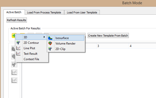


스퀴즈 핀은 주조시 주입 공급이 어려운 영역에서, 응고하는 동안 금속 수축을 보상하기 위해 사용되는 실제의 다이 캐스팅 머신의 동작을 모델링하는 해석을 할 수 있습니다. 스퀴즈 핀은 선택된 표면에 cylinderical squeeze pin을 추가하여, STL 파일 또는 대화식으로 생성 될 수 있습니다. Read the development note >
새로운 플런저 타입 형상이 추가 되었습니다. 강화된 압력 조건으로 macro-shrinkage 와 micro-porosity 제거를 지정할 수 있습니다.
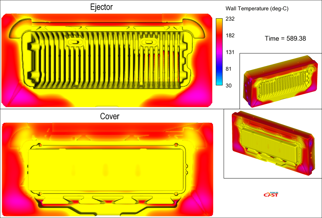
다이싸이클링 (Thermal die cycling, TDC) 모델에 새로운 두 가지의 단계가 추가되었습니다. 금형이 열린 상태에서 제품이 여전히 금형 내부에 있는 ejection 단계와, 금형이 닫혔지만 사출 바로전의 preparation 단계가 추가되었습니다. 또한, 마지막 싸이클만이 아닌 모든 금형 싸이클 모두 수렴된 결과를 전달하기 위해 TDC 솔버가 성능 손실 없이 최적화 되었습니다. Read the blog post >
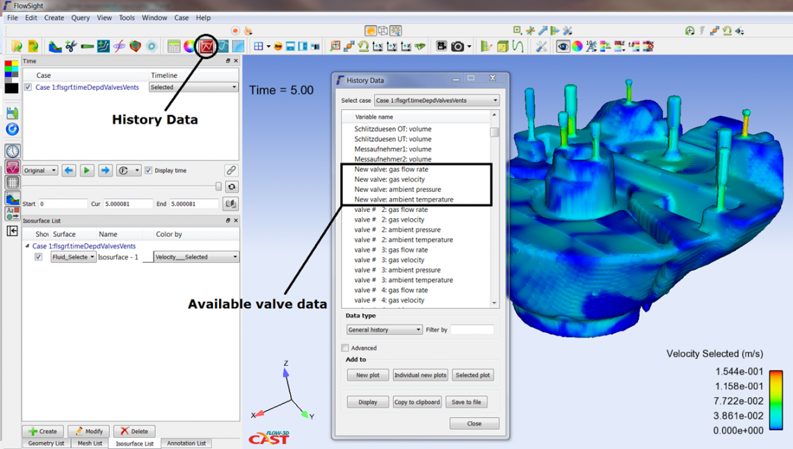
밸브와 밴트의 외부 압력과 온도는 이제 사용자가 다이 캐스팅 공정에서 충진중에 보다 실제적인 동작을 정의 할 수 있도록, 시간의 표 함수로서 정의 할 수있습니다. 밸브 및 벤트의 압력 및 온도는 프로세스 설계 단계에서 유용한 제품 내부에 설정된 프로브에 의해 제어 될 수 있습니다.
PQ2다이어그램의 사용은 사용자가 더 나은 슬리브의 플런저 실제 움직임과 유사하게 적용 할 수 있습니다. 새로운 기능은 실제 공정 변수가 아직 알려져 있지 않았을 때 다이캐스팅 설계 단계 중에 특히 유용합니다. Read the blog post >
냉각 채널은 금형 각각의 냉각 유로에 의해 제거되거나 추가된 열의 총량에 의해 제어 될 수 있습니다. Read the development note >
캐비테이션 모델은 유동 조건의 더 넓은 범위에 걸쳐 유체의 캐비테이션 거동을 나타내도록 개선되었습니다. 캐비테이션 생성에 대한 새로운 옵션은 경험적 관계를 기반으로, 기존의 일정한 속도로 생성되는 방식에서 보완되었습니다. 새로운 passive gas model 옵션은 open bubbles이 아닌 유체내에 cavitationg gas를 추적하여, 계산에 필요한 격자와 계산시간을 줄일 수 있습니다. Read the development note >
Two-fluid phase change model 은 과냉각을 포함하도록 확장되었습니다. 일정한 과냉각 온도를 정의하고 가스 온도가 응축이 일어나기 전에 포화점 이하로 내려갈 수 있게 함으로써 구현됩니다.
사용자가 FLOW-3D Cast v4.1 결과 파일들을 병합 및 제거 할 수 있는 편집 유틸리티
Restart 해석 결과 파일들(flsgrf.*)은 FlowSight 에서 하나의 연속적인 애니메이션 결과를 표시하기 위해 restart source 결과로 링크될 수 있습니다.
A new spatial quantity has been added to the solution output that stores the time that metal spent in contact with each geometric component, as well as the time spent by each component with metal.
열전달 계수, 열 침투 깊이, 밸브 손실 계수, 슬리브에 용탕량(깊이), 플런저의 속도를 계산할 수 있는 Calculators 기능이 Model Setup 창에서 바로 가능해졌습니다. 또한 유틸리티 메뉴에서도 가능합니다.


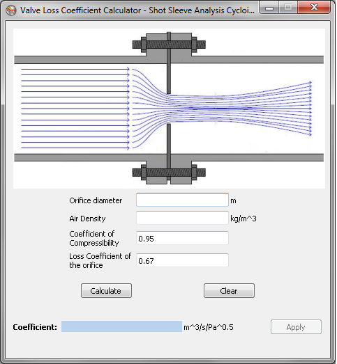
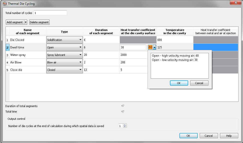
열전달 계수 데이터베이스와 각 싸이클 단계들이 입력되어있어 간편하게 다이싸이클링 해석을 하실 수 있습니다.
GMRES pressure solver의 속도가 솔버 데이터 구조의 최적화로 인해 2배까지 향상되었습니다. 이로 인해 메모리 사용량이 20% 미만으로 증가할 수 있습니다. Read the blog post >
Sampling volume 기능은 STL로 정의할 수 있습니다. 각 sampling volume에 의해 계산된 양들의 목록은 유체의 부피, 최대/최소 온도, 파티클의 갯수와 같은 전체 해석 영역에 대해 모두 같은 양이 되도록 확장되었습니다.
구조분석 모델의 성능이 부분적인 coupling으로 해석 솔버의 병렬화와 최적화를 통해 향상되었습니다.
Workspaces 를 이전에 설치된 FLOW-3D에서 가져올 수 있습니다. Workspaces 와 사용자가 선택한 시뮬레이션들을 복사할 수 있습니다.
Simulation pre-check 기능은 preprocessor checks를 포함하고, 문제가 발생하는 경우 링크됩니다.
Depth-peeling 옵션은 transparent geometries 를 좀 더 잘 표현하고, v4.0보다 10배 빨라졌습니다.
Baffles, history probes, void/fluid pointers, valves, mass-momentum sources, squeeze pins에 대한 새로운 대화형 생성 기능이 추가되었습니다. 또한 probing과 clipping 도구들이 대화형으로 개선되었습니다.
모든 objects (e.g., mesh blocks)은 활성화/비활성화 할 수 있습니다.
솔버 메세지 파일에 short-print로 추정된 잔여 해석 시간이 추가 되었습니다.
테이블 형식의 데이터에서 선택된 데이터를 마우스 오른쪽 버튼을 클릭하여 csv파일 또는 외부 파일에 복사, 저장할 수 있습니다.


 | |
| Industry | Computational Fluid Dynamics Software |
|---|---|
| Founded | 1980 |
| Founder | Dr. C.W. “Tony” Hirt |
| Headquarters |
Santa Fe, New Mexico, USA
United States
|
|
Key people
| Dr. Amir Isfahani, President & CEO |
| Products | FLOW-3D, FLOW-3D CAST, FLOW-3D AM, FLOW-3D CLOUD, FlowSight |
| Services | CFD consultation and services |
FLOW-3D는 미국 뉴멕시코주(New Mexico) 로스알라모스(Los Alamos)에 있는 Flow Scicence, Inc에서 개발한 범용 전산유체역학(Computational Fluid Dynamics) 프로그램입니다. 로스알라모스 국립연구소의 수치유체역학 연구실에서 F.Harlow, B. Nichols 및 T.Hirt 등에 의해 개발된 MAC(Marker and Cell) 방법과 SOLA-VOF 방식을 기초로 하여, Hirt 박사가 1980년에 Flow Science, Inc사를 설립하여 계속 프로그램을 발전시켰으며 1985년부터 FLOW-3D를 전세계에 배포하였습니다.
유체의 3차원 거동 해석을 수행하는데 사용되는 CFD모형은 몇몇 있으나, 유동해석에 적용할 물리모델 선정은 해석의 정밀도와 밀접한 관계가 있으므로, 해석하고자 하는 대상의 유동 특성을 분석하여 신중하게 결정하여야 합니다.
FLOW-3D는 자유표면(Free Surface) 해석에 있어서 매우 정확한 해석 결과를 제공합니다. 해석방법은 자유표면을 포함한 비정상 유동 상태를 기본으로 하며, 연속방정식, 3차원 운동량 보전방정식(Navier-Stokes eq.) 및 에너지 보존방정식 등을 적용할 수 있습니다.
FLOW-3D는 유한차분법을 사용하고 있으며, 유한요소법(FEM, Finite Element Method), 경계요소법(Boundary Element Method)등을 포함하여 자유표면을 포함하는 유동장 해석(Fluid Flow Analysis)에서 공기와 액체의 경계면을 정밀하게 표현 가능합니다.
유체의 난류 해석에 대해서는 혼합길이 모형, 난류 에너지 모형, RNG(Renormalized Group Theory) k-
FLOW-3D는 비압축성(Incompressible Fluid Flow), 압축성 유체(Compressible Fluid Flow)의 유동현상 뿐만 아니라 고체와의 열전달 현상을 해석할 수 있으며, 비정상 상태의 해석을 기본으로 합니다.

FLOW-3D v12.0은 모델 설정을 간소화하고 사용자 워크 플로우를 개선하는 GUI(그래픽 사용자 인터페이스)의 설계 및 기능에 있어 중요한 변화를 가져왔습니다. 최첨단 Immersed Boundary Method는 FLOW-3Dv12.0솔루션의 정확도를 높여 줍니다. 다른 특징적인 주요 개발에는 슬러지 안착 모델, 2-유체 2-온도 모델, 사용자가 자유 표면 흐름을 훨씬 더 빠르게 모델링 할 수 있는 Steady State Accelerator등이 있습니다.
힘과 에너지 손실에 대한 정확한 예측은 솔리드 바디 주변의 흐름과 관련된 많은 엔지니어링 문제를 모델링하는 데 중요합니다. FLOW-3D v12.0의 릴리스에는 이러한 문제 해결을 위해 설계된 새로운 고스트 셀 기반 Immersed Boundary Method (IBM)가 포함되어 있습니다. IBM은 내부 및 외부 흐름을 위해 벽 근처 해석을 위해 보다 정확한 솔루션을 제공하여 드래그 앤 리프트 힘의 계산을 개선합니다.
2유체 열 전달 모델은 각 유체에 대한 에너지 전달 공식을 분리하도록 확장되었습니다. 이제 각 유체에는 고유한 온도 변수가 있어 인터페이스 근처의 열 및 물질 전달 솔루션의 정확도를 향상시킵니다. 인터페이스에서의 열 전달은 시간의 표 함수가 될 수 있는 사용자 정의 열 전달 계수에 의해 제어됩니다.
중요 추가 기능인 새로운 슬러지 침전 모델은 도시 수처리 시설물 응용 분야에 사용하면 수처리 탱크 및 정화기의 고형 폐기물 역학을 모델링 할 수 있습니다. 침전 속도가 확산된 위상의 방울 크기에 대한 함수인 드리프트-플럭스 모델과 달리, 침전 속도는 슬러지 농도의 함수이며 기능적인 형태와 표 형태로 모두 입력 할 수 있습니다.
이름이 암시하듯이, 정상 상태 가속기는 안정된 상태의 솔루션에 대한 접근을 가속화합니다. 이는 작은 진폭의 중력과 모세관 현상을 감쇠하여 이루어지며 자유 표면 흐름에만 적용됩니다.
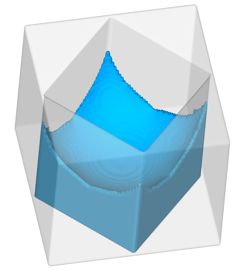
보이드 입자가 버블 및 위상 변경 모델에 추가되었습니다. 보이드 입자는 항력과 압력 힘을 통해 유체와 상호 작용하는 작은 기포의 역할을 하는 붕괴된 보이드 영역을 나타냅니다. 주변 유체 압력에 따라 크기가 변경되고 시뮬레이션이 끝난 후 최종 위치는 공기 침투 가능성을 나타냅니다.
침전물의 정확성과 안정성을 향상시키기 위해 침전물의 운반과 침식 모델을 정밀 조사하였다. 특히, 침전물 종에 대한 질량 보존이 크게 개선되었습니다.
고정 압력 경계 조건에는 이제 압력 및 유체 비율을 제외한 모든 유량이 해당 경계의 상류에 있는 흐름 조건을 반영하는 ‘유출’ 옵션이 포함됩니다. 유출 압력 경계 조건은 고정 압력 및 연속성 경계 조건의 혼합입니다.

시뮬레이션 중에 입자 소스는 이동할 수 있습니다. 시간에 따른 변환 및 회전 속도는 표 형식으로 정의됩니다. 입자 소스의 운동은 소스에서 방출 된 입자의 초기 속도에 추가됩니다.
중력 및 비 관성 기준 프레임 모델에서 시간 함수로서의 무게 중심의 위치는 외부 파일의 표로 정의할 수 있습니다. 이 기능은 연료를 소모하는 로켓을 모델링하고 단계를 분리할 때 유용합니다.
가장 간단한 부피 기반 공기 유입 모델 옵션이 기존 질량 기반 모델로 대체되었습니다. 질량 기반 모델은 부피와 달리 주변 유체 압력에 따라 부피가 변화하는 동안 흡입된 공기량이 보존되기 때문에 물리학적 모델입니다.
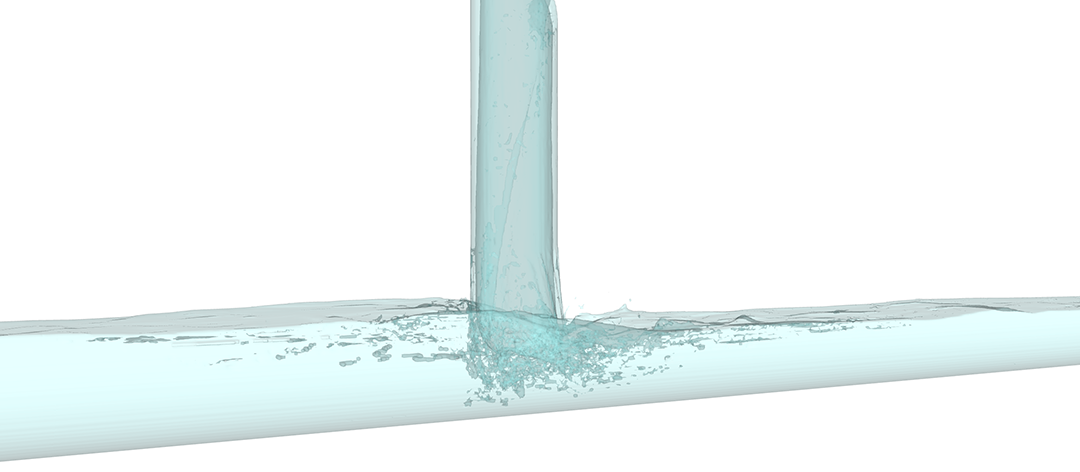
유동 표면에서 생성된 추적 물질은 분자 및 난류 확산 과정에 의해 확산될 수 있으며, 예를 들어 실제 오염 물질의 거동을 모방합니다.
이제 온도를 포함하여 단위계 시스템을 완전히 정의해야 합니다. 표준 단위 시스템이 제공됩니다. 또한 사용자는 선택한 옵션에서 질량, 시간 및 길이 단위를 정의하여 편리하며, 사용자 정의된 단위를 사용할 수 있습니다. 사용자는 또한 압력이 게이지 단위로 정의되는지 절대 단위로 정의되는지 여부를 지정해야 합니다. 기본 시뮬레이션 단위는 Preferences(기본 설정)에서 설정할 수 있습니다. 단위를 완벽하게 정의하면 FLOW-3D는 물리적 수량에 대한 기본 값을 정의하고 범용 상수를 설정할 수 있으므로 사용자가 필요로 하는 작업량을 최소화할 수 있습니다.
Manning의 거칠기 계수는 지형 표면의 전단 응력 평가를 위해 천수(shallow water) 모델에서 구현되었습니다. 표면 결함의 크기를 기반으로 기존 거칠기 모델을 보완하며이 모델과 함께 사용할 수 있습니다. 표준 거칠기와 마찬가지로 매닝 계수는 구성 요소 또는 하위 구성 요소의 속성이거나 지형 래스터 데이터 세트에서 가져올 수 있습니다.
하단 및 상단 경계 좌표의 정의만으로 수직 방향의 메시 설정이 단순화되었습니다.
사용자는 이제 여러 하위 구성 요소로 구성된 구성 요소에 회전, 변환 및 스케일링 변환을 적용하여 복잡한 형상 어셈블리 설정 프로세스를 단순화 할 수 있습니다. GMO (General Moving Object) 구성 요소의 경우, 이러한 변환을 구성 요소의 대칭 축과 정렬되도록 신체에 맞는 좌표계에 적용 할 수 있습니다.
시뮬레이션 중에 솔버가 사용하는 스레드 수를 변경하는 기능이 런타임 옵션 대화 상자에 추가되어 사용 가능한 스레드를 추가하거나 다른 태스크에 자원이 필요한 경우 스레드 수를 줄일 수 있습니다.
활성 시뮬레이션 제어가 형상 구성 요소와 관련된 heat sources로 확장되었습니다. history probes로 열 방출을 제어 할 수 있습니다.
질량 및 질량/모멘트 소스의 유체 온도는 이제 테이블 입력을 사용하여 시간의 함수로 정의 할 수 있습니다.
공극으로의 복사 열 전달을위한 방사율 계수는 이제 사용자가 방사율과 스테판-볼츠만 상수를 지정하도록 요구하지 않고 직접 정의됩니다. 후자는 이제 단위 시스템을 기반으로 솔버에 의해 자동으로 설정됩니다.
새로운 사용자 정의 가능 소스 루틴이 추가되었으며 사용자의 개발 환경에서 액세스 할 수 있습니다.
| 소스 루틴 이름 | 기술 |
| cav_prod_cal | Cavitation 생성과 소산 비율 |
| sldg_uset | 슬러지 침전 속도 |
| phchg_mass_flux | 증발 및 응축으로 인한 질량 플럭스 |
| flhtccl | 유체 # 1과 # 2 사이의 열전달 계수 |
| dsize_cal | 2 상 흐름에서 동적 액적 크기 모델의 응집 및 분해 속도 |
| elstc_custom | 점탄성 유체에 대한 응력 방정식의 Source Terms |
FLOW-3D 사용자 인터페이스는 완전히 새롭게 디자인되어 현대적이고 평평한 구조로 사용자의 작업 흐름을 획기적으로 간소화합니다.
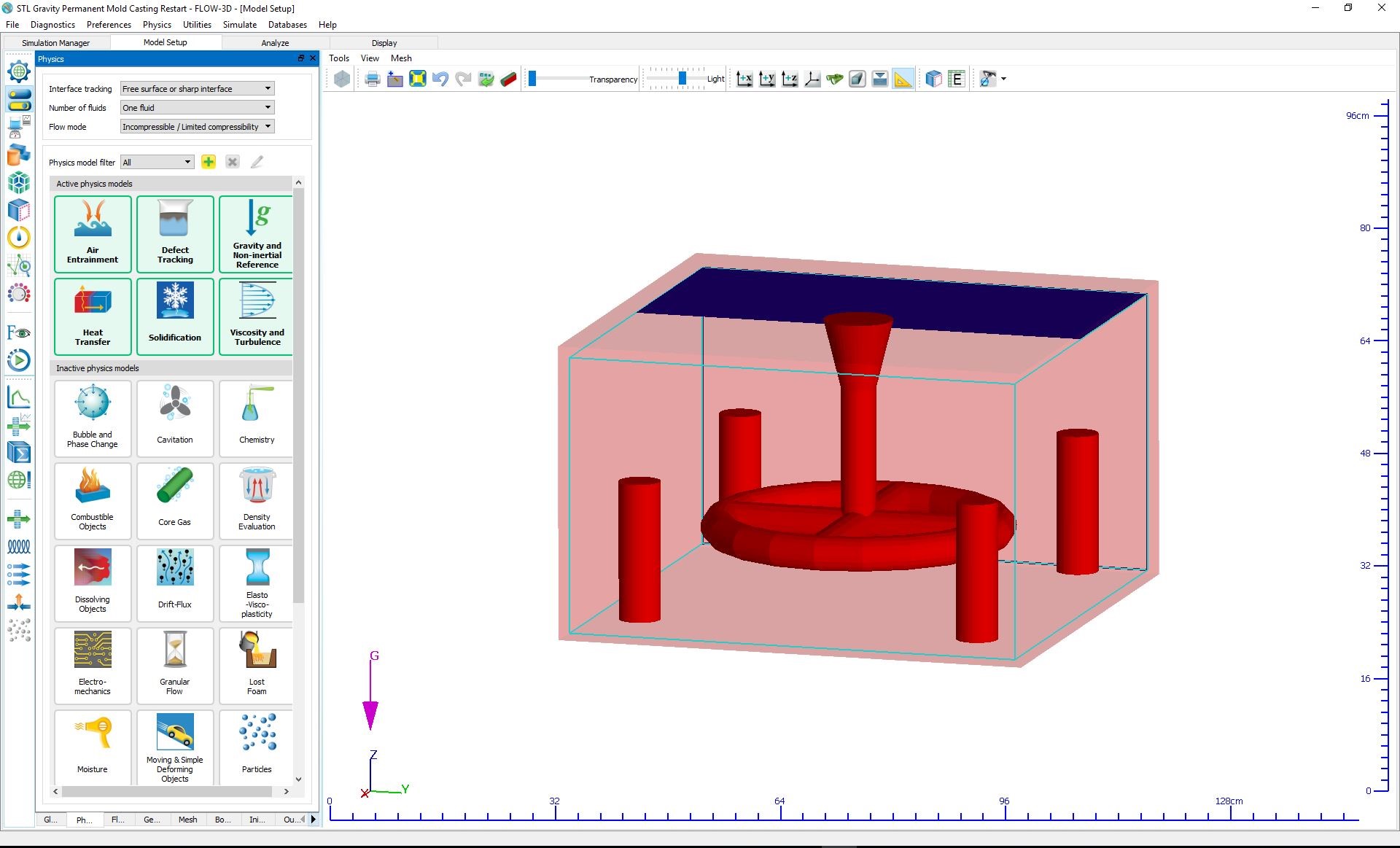
Physics, Fluids, Mesh 및 FAVOR ™를 포함한 모든 설정 작업이 지오 메트리 윈도우 주변에서 독 위젯으로 변환되어 모델 설정을 단일 탭으로 요약할 수 있습니다. 이러한 전환으로 인해 이전 버전의 복잡한 접이식 트리가 훨씬 깨끗하고 효율적인 메뉴 프레젠테이션으로 대체되어 사용자는 ModelSetup탭을 떠나지 않고도 모든 매개 변수에 쉽게 액세스 할 수 있습니다.
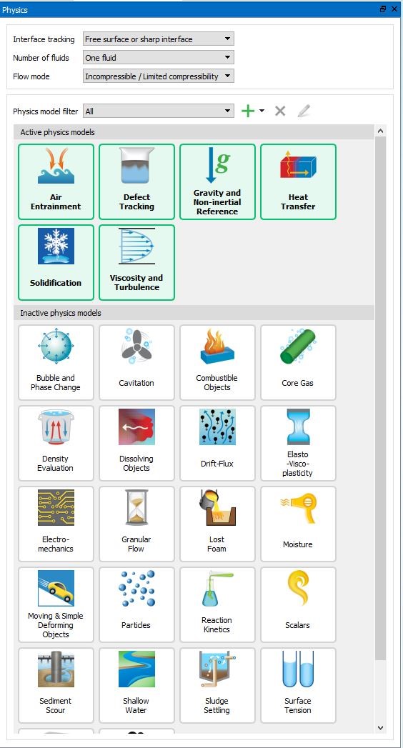
새로운 모델 설정 디자인에는 설정 프로세스의 각 단계를 나타내는 새로운 아이콘이 있습니다.
새 RSS 피드부터 FLOW-3D v12.0의 시뮬레이션 관리자 탭이 개선되었습니다. FLOW-3D 를 시작하면 사용자에게 Flow Science의 최신 뉴스, 이벤트 및 블로그 게시물이 표시됩니다.
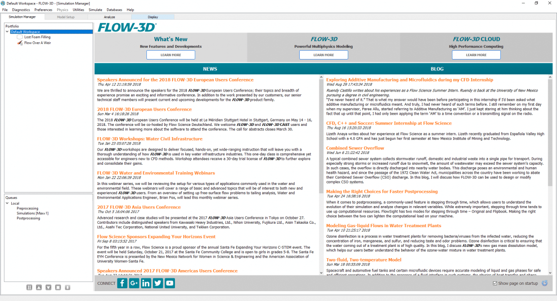
시뮬레이션을 실행할 때 중요한 작업은 모니터링입니다. FLOW-3Dv1.0에서는 사용자가 시뮬레이션을 더 잘 모니터링할 수 있도록 SimulationManager의 플로팅 기능이 향상되었습니다. 사용자는 시뮬레이션 런타임 그래프를 통해 모니터링할 사용 가능한 모든 일반 기록 데이터 변수를 선택하고 각 그래프에 여러 변수를 추가할 수 있습니다. 이제 런타임에서 사용할 수 있는 일반 기록 데이터는 다음과 같습니다.

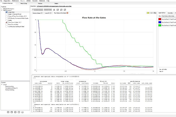
용자는 이제 새로운 FAVOR ™ 독 위젯을 통해 적합한 메쉬 블록을 시각화 할 수 있습니다.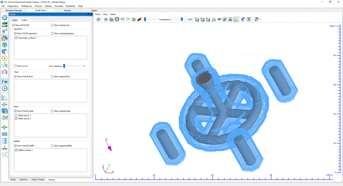
응고 모델은 열전달이 활성화되고(Physics → Heat Transfer → Fluid internal energy advection) 유체비열(Fluids → Fluid 1 → Thermal Properties → Specific heat)과 전도도(Fluids → Fluid 1 → Thermal Properties → Thermal Conductivity) 이 지정될 때 사용될 수 있다. 단지 유체 1만 상 변화를 겪을 수 있다.
응고모델을 활성화하기 위해 Fluids → Fluid 1 → Solidification Model 을 체크하고 물성 Fluids → Fluid 1 → Solidification Model 가지에서 Liquidus temperature, Solidus temperature, 그리고 Latent heat of fusion 를 지정한다. 가장 간단한 모델(Latent Heat Release Definition 에 펼쳐지는 메뉴에서 Linearly with constant 를 선택)에서, 잠열은 물체가 Liquidus 에서 Solidus 온도로 냉각될 때 선형적으로 방출된다. 고상에서의 상변화열을 포함하는, 잠열 방출의 더 자세한 모델을 위해 온도의 함수로 잠열방출을 정의하기 위해 Specific energy vs. temperature 또는 Solid fraction vs. temperature 선택을 사용한다. 이 지정에 대한 더 자세한 내용은 이론 매뉴얼의 Heat of Transformation 를 참조한다.
응고는 유체의 강직성 및 유동저항을 뜻한다. 이 강직성은 두 가지로 모델링 된다. 낮은 고상율에 대해 즉 Fluids → Fluid 1 → Solidification Model → Solidified Fluid 1 Properties → Coherent Solid Fraction 의 coherency 점 밑에서는 점도는 고상율의 함수이다. 간섭 고상율보다 큰 고상율에 대해서는 고상율의 함수에 비례하는 항력계수를 갖는 Darcy 형태의 항력이 이용된다. 이 항력은 모멘텀 방정식에 (bx,by,bz) 로써 추가된다- Momentum Equations 를 보라. 이 항력의 계산은 Solidification Drag Model 에서 기술된다. 항력계수는 사용자가 유동저항에 양을 조절할 수 있는 Coefficient of Solidification Drag 인자를 포함한다. 항력계수는 FLOW-3D 출력에서 기록된 속도에 상응하는 지역 상 평균 속도에 의해 곱해진다.
Fluid 1 Properties)을 지나면 항력은 무한대가 되고 계산격자 관련하여 유동이 있을 수 없다(단 예외로 Moving Solid Phase를 참조).
Note
모든 유체가 완전히 응고하면 모사를 정지시키기 위해 General → Finish condition → Solidified fluid fraction 를 이용한다. General → Finish condition → Finish fraction 은 모사를 중지하기 위한 고상율 값을 정한다.
주조 시 mushy zone 은 액상과 고상이 혼합물로 존재하는 지역이다. 이 지역 혼합점도는 동축의 수지상 조직(과냉각된 액체 안에서 방사상으로 자라는 결정으로 된 구조) 이 액체 안에서 자유롭게 부유할 때 영향을 미친다.
일단 수지상 조직의 간섭성이 발생하여 고정된 고상 망이 형성되면 액상이 고정된 다공 수지상 구조를 통과해야 하므로 추가의 유동손실이 발생한다. 다른 방법으로는 간섭점을 지난 액/고상 혼합물은 다공물질을 통한 유동 대신에 고점도의 유체로 간주될 수 있다. 점성유체로 간주하는 접근은 예를 들면 연속 이중 롤 주조 과정같이 고상이 계속 이동 및 변형할 때 유용하다.
응고에 의한 항력계수를 정의하기 위해 사용자는 우선 열전달 및 응고모델을 활성화 해야 한다. 이들은 Model Setup → Physics 탭 에서 활성화될 수 있다. 수축모델 또한 응고모델 창에서 활성화될 수 있다.
일단 Solidification 모델이 활성화되면 항력의 공식이 지정될 필요가 있다. Solidification대화의 밑 좌측 모퉁이에서 Porous media drag-based 와 Viscosity-based 의 항력공식 중의 선택을 한다.
밑에 주어진 Darcy법칙은 수지상 구조를 위한 다공매질내의 수학적 유동기술이다.[Poi87].
(19)
여기서 u 는 수지상 구조 내 유동의 속도이고 ∇P 는 지역 압력구배, 그리고 K 는 mushy 구역의 특정 투수성이다. 이 방정식은 단지 유동이 거의 정상 상태이고, 관성효과가 없으며 유체의 체적율이 일정하고 균일하며 액체-액체의 상호작용 힘이 없을 때 유효하다. 투수성을 정의하는데 이용될 수 있는 대 여섯 개의 모델이 있으나 FLOW-3D 는 밑에 보여주는 Blake-Kozeny 을 이용한다. 다른 모델들은 코드와 함께 제공되는 소스코드를 사용자 사양에 맞게 수정하여 추가할 수 있다.
(20)
여기서
C2 는 전형적으로 와 같은 비틀림
fs 는 고상율이고
λ1는 유동을 위한 특정 치수
이 응용에서 수지상 가지 간격(DAS)이 이용된다.
(21)
수지상 가지 간격(DAS)에 대한 일반적인 값들은 밑에 주어져 있다.
| COOLING RATE, K/s | PRODUCTION PROCESSES | DENDRITE ARM SPACING,  |
|---|---|---|
 to to  |
large castings | 5000 to 200 |
to  |
small castings, continuous castings, die castings, strip castings, coarse powder atomization | 200 to 5 |
to  |
fine powder atomization, melt spinning, spray deposition, electron beam or laser surface melting | 5 to 0.05 |
Range of cooling rates in solidification processes [CF85]
FLOW-3D 는 액고상 변화를 모델링하기 위해 다공매질항력을 이용한다. 항력은 고상율의 함수이다. 사용자에게 두 수축모델이 이용 가능하다; 급속 수축 모델 과 완전 유동모델. 급속 수축 모델은 상변화와 연관된 체적변화를 고려하지 않으며 유체는 정지해 있다고 가정한다. 완전 유동모델은 상변화가 관련된 체적변화를 고려한다. 항력은 투수성에 역으로 비례하므로 다음과 같이 표현될 수 있다.
(22)
여기서, Fd 는 FLOW-3D 에서 사용된 항력계수이다. 이 항력계수는 지역 속도에 의해 곱해지고 모멘텀 방정식의 오른쪽에서 차감된다 (Momentum Equations 참조). 식 (11.22) 를 재정리하고 식 (11.21) 로부터의 투수성에 치환하면 다음을 얻는다.
 ,
, .
.See also
편절 모델은 대류와 확산에 의한 용질 이동에 따른 이원합금 요소에서의 변화를 모델링 하도록 되어 있다. 이 모델링은 Physics → Solidification 로 부터 될 수 있다.
Activate binary alloy segregation model 을 체크하고 편절 모델을 활성화한다.
여러 온도에서 평형에 있는2원합금 요소농도를 정의하는 상태도는 직선의 고상선 및 액상선을 가진다고 가정된다. 상태도는 입력데이터에 의해 구성되고 전처리 그림파일 prpplt 에 포함된다. Analyze → Existing 에서 이용 가능하다
Macro-Segregation Model (under Fluids → Fluid 1 → Solidification Model)에 관련된 일부 유체물성 트리가 밑에 보여진다. 상태도는 Reference Solute Concentration 에서의 the Solidus 와 Liquidus Temperatures 값들에 의해 정의된다. 추가로 Concentration Variables 밑의 Partition coefficient 도 정의되어야 한다. 그렇지 않으면 Pure Solvent Melting Temperature 가 정의될 수 있다. Partition coefficient 와 Pure Solvent Melting Temperature 둘 다가 지정되면 용매 용융 온도는 상태도로부터 재 정의된다.
Eutectic Temperature 또는 Eutectic Concentration 는 융해작용을 정의하기 위해 지정될 수 있다. 또 이 두 변수가 다 지정되면 Eutectic Concentration 은 상태도에서 재 정의된다.
Diffusion Coefficients 는 고상과 액상 사이의 용질의 확산계수 비율을 정의한다. 액체 내의 용질의 분자 확산계수는 Physics → Solidification 에서 specifying Solute diffusion coefficient 를 지정함으로써 정해진다. RMSEG 는 용질의 난류 확산계수 승수를 정의한다; 이는 입력파일에서 직접 지정된다.
용질 재 분배에 의한 농도변화가 중요하면 Physics → Density evaluation → Density evaluated as a function of other quantities를 정하고 용질농도의 선형함수로써 금속농도를 정의하기 위해 Fluids → Segregation model 밑의 Solutal Expansion Coefficient 를 용질 확장계수로 지정한다. 이 경우 Reference Solute Concentration 이 기준농도로 사용될 것이다. 추가로 Fluids → Fluid 1 → Density Properties → Volumetric Thermal Expansion 은 액체 내 열부력 효과를 참작하기 위해 지정될 수 있다(또한 Buoyant Flow참조).
초기 용질농도는 Meshing & Geometry → Initial → Global → Uniform alloy solute concentration 에서 지정될 수 있다. 불 균일한 초기 분포는 Alloy solute concentration 밑의 초기유체 구역 안에서 정의될 수 있다. 추가로 농도는 Initial Conditions: Region Values 에서 기술된 바와 같이 2차함수를 사용하는 부분을 편집하여 공간상의2차함수로 변화할 수 있다. 압력과속도 경계에서 용질 경계조건을 정하기 위해 Boundaries → Boundary face → Solute concentration 를 이용한다.
액상 및 고상 구성은 후처리에서 데이터 변환을 이용하여 그려질 수 있다. 용융 응고금속은 금속 내 용융의 질량 분율을 저장하는 SLDEUT 를 그림으로써 가시화될 수 있다.
액상 내 열구배가 크면 Physics → Heat Transfer → Second order monotonicity preserving 를 지정함으로써 더 나은 정확성을 위해 고차원 이류법을 사용한다.
mushy 지역에서의 유동손실은 수지상 가지 간격(DAS)의 함수인 Fluids → Fluid 1 → Solidification Model → Solidified Fluid 1 Properties → Coefficient of Solidification Drag 에 의해 조절된다. 후자는 이 모델에 의해 계산되지 않으므로 사용자는 Coefficient of Solidification Drag 를 지정해야 한다
Note
미세다공모델은 단지 응고(Solidification참조)를 모델링할 때 사용될 수 있고 Physics → Solidification → Activate micro-porosity model 에서 활성화된다. 필요한 입력은 Fluids → Densities → Fluid 1 and Fluids → Solidification Properties → Solidified Fluid 1 Properties → Density 에서 정의되는 액체와 고상 유체밀도이며 고상유체밀도는 액체밀도보다 크다. 또한 Fluids → Fluid 1 → Solidification Model → Solidified Fluid 1 Properties 안에 있는 Critical Solid Fraction 은 1.0보다작게 설정되어야 한다.
Square of the speed of sound at critical solid fraction 값이 정의될 수 있다. 이는 수축에 의해 mushy 지역에서 전개되는 커다란 음압에서의 응고유체의 압축성을 기술한다. Critical pressure at which gas pores can form 값은 모델이 Initial tab 탭에서 또는 재 시작 데이터에서 정의되는 유체내의 초기 압력과 결합되도록 한다.
Intensification pressure 또한 다공 생성을 지연시키기 위해 응고 시 shot sleeve plunger 에 의해 형성되는 추가압력을 고려하기 위한 고압 주조모사를 위해 정의될 수 있다. Intensification pressure 가 클수록 더 적은 양의 다공이 주조 시 응고 과정에서 발생할 것이다.
미세 다공 모델은 응고 모델의 활성화 이외의 어떤 다른 설정을 필요로 하지 않는다. 이는 완전 유동방정식이나 속도장이 0인 경우, 즉 순수한 열 문제에서도 함께 사용될 수 있다.
이 모델은 후처리 과정의 공간 및 이력에서 사용 가능한 Percent micro-porosity 라고 불리는 추가 출력 양을 생성한다.
Note
A Flow Science technical note on modeling micro-porosity (TN66) can be found at http://users.flow3d.com/technical-notes/.
| MAIN VARIABLES: | OBS: | IFOB, UTOBS, VTOBS, WTOBS |
이동고상 선택은 연속주조 모델링을 가능하게 한다. Continuous Casting Phantom 요소는 응고된 이동 유체가 있는 지역에서 정의된다. 이는 지정된 영역을 차지하지만 정의에만 존재하므로 환영요소라고 한다. 이는 실제로 면적이나 체적을 차지하지 않으므로 체적이 없고 결과에서도 고체요소로 보이지 않는다. 이는 Meshing & Geometry → Geometry → Component → Component Type 옆 펼쳐지는 메뉴에서 정의된다.
다른 방법으로는 입력파일(prepin.*)에서 IFOB(N) 변수가 4로 지정되고 N 은 요소 번호이다. 이 파일은 File → Edit Simulation…. 을 선택하여 이용될 수 있다. 또한 입력파일에서 시간의 함수(TOBS(t) 에 의해 지정되는)일 수 있는 가상 요소의 속도성분 UTOBS(t,N), VTOBS(t,N) 그리고 WTOBS(t,N) 이 지정된다.
Fluids → Fluid 1 → Solidification Properties → Solidified Fluid 1 Properties → Coherent Solid Fraction 에 의해 정의된 간섭 고상율 보다 큰 고상율에 대해서는 Darcy 형태의 항력 이 유체를 가상 요소의 속도로 움직이게 하는데 사용된다. 고상율이 Fluids → Fluid 1 → Solidification Properties → Solidified Fluid 1 Properties → Critical Solid Fraction 에서 지정된 경직점을 능가하게 되면 가상 요소의 속도를 따라 움직일 것이다.
Note
체적 수축은 소재가 응고하고 응고소재의 밀도가 액체소재의 밀도보다 클 때 나타난다(즉, Fluids → Fluid 1 → Solidification Model → Solidified Fluid 1 Properties → Density > Fluids → Fluid 1 → Density Properties → Density). 수축모델은 그러므로 Solidification 모델이 활성화되어야 하고 고상/액상의 두 밀도가 정의되어야 한다. 수축은 단지 1유체의 뚜렷한 경계면 문제에서만 모델링 될 수 있다.
두 가지 수축모델이 있다. Shrinkage model with flow effects 를 선택하면 완전 열 유체방정식을 해석한다(이론 매뉴얼의Solidification Shrinkage and Porosity Models 참조). 그러나 이 모델은 특히 장시간의 응고가 고려되면 컴퓨터 계산시간이 많이 소요된다. 다른 방법으로 사용자 Interface 에 Shrinkage model 이라고 불리는 단순모델이 있다.
이 모델은 단지 열전달 방정식의 해석에 의존하며 특히 내재적 열전달 모델 (Numerics → Explicit/implicit options → Heat transfer → Implicit –Thermal solution 참조)과 사용시에 빨리 해석할 수 있다. 액체 체적 내로의 유동 통로가 없을 때 내부공동이 발생한다.
이 두 모델에서 유입은 mushy 지역 유동에 대한 항력계수를 계산함으로써 정의된다. 격자 내 모든 점에서의 항력함수는 상수승수 Fluids → Solidification properties → Other → Coefficient of Solidification Drag (Solidification Drag Model 참조)를 가지는 지역 고상율의 함수로 계산된다. 항력함수의 역의 값은 공간 그림에서 가시화 될 수 있다: 이 그림을 위한 변수이름은 ‘drag coefficient’ 이다.
Mushy 지역에서의 커다란 유동 손실에 따른 부분적 유입이 Shrinkage model with flow effects 에서 발생할 수 있지만 단순화된 Shrinkage model 은 완전 유입이 아니면 유입이 없게 된다. 후자는 유입 통로를 따라 지역 고상율이 Fluids → Fluid 1 → Solidification Model → Solidified Fluid 1 Properties → Critical Solid Fraction (디폴트는1.0)에서 정의된 임계값보다 커질 때 발생한다. 추가로 고립된 액체 내의 금속의 고상율이 Coherent Solid Fraction 에 도달할 때까지 단순모델에서의 유입은 고립부 상부로부터 발생한다. 그 후로는 유입이 고립부의 가장 뜨거운 부분에서부터 발생한다.
모든 유체가 완전히 응고되면 모사가 정지하도록 General → Additional finish condition → Solidified fluid fraction 를 사용한다. 변수 Finish fraction 는 유체가 지정된 고상율에 도달할 때 모사가 정지하도록 하는데 사용될 수 있다.
Note
이송 방향을 결정하기 위해 단순 수축 모델에서 중력이 필요하며 좌표축 중 하나를 따라야합니다. 둘 이상의 중력 구성 요소가 0이 아닌 경우, 가장 큰 중력 구성 요소가 공급 방향을 결정하는 데 사용됩니다.
See also

FLOW-3D의 TSE(Thermalstressdiversion)모델은 모델링 가능한 주조 프로세스의 범위를 확장합니다. FSI/SETSE모델은 주변 유체, 열 구배 및 지정된 구속 조건의 압력에 대응하여 솔리드 및 단단한 구성 요소의 응력 및 변형을 모델링 하는 유한 요소 접근 방식을 사용하여 유체와 솔리드 사이의 완전 결합 상호 작용을 설명합니다.
균일하지 않은 냉각에 의해 발생하는 응고 과정 동안 열 스트레스가 발생합니다. 이러한 응력은 주형 벽의 수축 및 주물 형상의 불규칙에 의해 영향을 받습니다.
Von Mises stresses in a solidified aluminum V6 engine block
위의 시뮬레이션은 VonMises가 단단한 알루미늄 V6엔진 블록에서 응력을 나타냅니다. 이 블록은 강철 다이 내에서 주조된 알루미늄 A380합금으로 구성되어 있습니다.
알루미늄의 주입 온도는 527°C였으며 초기 다이 온도는 125°C였습니다. 부품을 60초 동안 다이 내에서 냉각한 후 주변 조건(125°C)에서 9분 동안 부품을 계속 냉각시켜 총 10분의 시뮬레이션 시간을 제공했습니다. 표시된 VonMises 응력은 부품 내 전단 응력의 크기를 측정한 것이며, 따라서 찢어지기 쉬운 부위를 보여 줍니다.
응력은 금형과 응고 금속에서 동시에 계산할 수 있습니다. FLOW-3D의 구조화된 메쉬를 초기 템플릿으로 사용하여 자동으로 메쉬 작업을 수행할 수 있습니다. 사용자는 중첩 또는 링크된 메쉬 블록을 만들고 V1.1.0의 새로운 적합한 메쉬 기능을 사용하여 메쉬의 로컬 해상도를 제어할 수 있습니다. 또는, Exodus-II형식의 타사 메쉬 생성 소프트웨어에서 유한 요소 메쉬를 가져올 수 있습니다.
아래에 표시된 알루미늄 커버는 강철 다이 내 알루미늄 A380합금으로 구성되어 있습니다. 주입 온도는 654°C였으며 초기 다이 온도는 240°C였습니다. 부품이 다이 내에서 6s동안 냉각되었으며 이때 부품이 완전히 경화되었습니다(러너 시스템 제외). 그런 다음 다이를 열고 부품이 주변 조건(25°C)에서 10초 이상 냉각되도록 했습니다. 그런 다음 탕도(runner)시스템을 제거했고, 이후 주변 조건에서 10초간 더 냉각했습니다. 여기에 표시된 정상 변위는 부품 표면의 움직임을 나타내며, 최대 변형 영역을 강조하기 위해 30회 증폭됩니다.
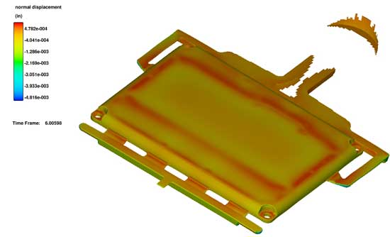
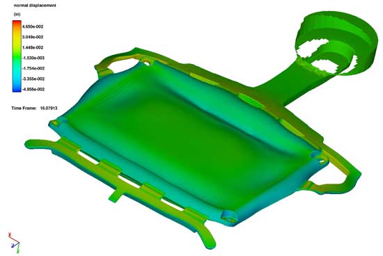
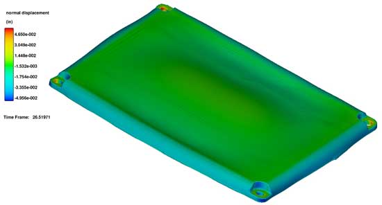
FLOW-3Dv11의 새로운 기능은 인접한 FSI(유체-구조물 상호 작용)구성 요소 및/또는 TSE(열 스트레스 진화)고체화된 유체 영역 간의 탄성 응력을 결합할 수 있는 기존의 유한 요소 고체 역학 용제의 업그레이드입니다. 이 새로운 기능은 복합 재료 부품(예:주형에서 응고되는 금속 주물 응고제 또는 바이메탈 게이지)의 열 응력과 변형을 시뮬레이션하고 반경 게이트 및 파이프 라인 지지 시스템과 같은 연결된 유압 구조에 가해지는 힘을 시뮬레이션하는 등 다양한 모델링 가능성을 열어 줍니다.
모델에는 복잡한 프로세스를 효율적으로 계산할 수 있는 여러가지 옵션이 있습니다.
이 옵션은 인접 FSI구성 요소가 응력을 교환하지 않는 단순화된 경우를 나타냅니다. 그것은 계산적으로 효율적이며 요소들 간의 스트레스 상호 작용이 중요하지 않은 시나리오에 적합하다.
전체 커플링 옵션은 서로 다른 재료 특성을 가진 인접 FSI구성 요소를 모델링 하기 위한 것입니다. 두 구성 요소는 서로 당기거나 미끄러질 수 없지만 인터페이스의 응력은 구성 요소 간에 전달됩니다. 이는 바이메탈과 같이 접합된 구조물을 모델링 하는 데 이상적입니다.
부분 커플링 옵션은 인접 FSI구성 요소가 마찰력과 정상적인 힘을 통해 상호 작용하지만 분리될 수 있는 일반적인 문제를 모델링 하기 위한 것. 이 옵션은 FSI구성 요소와 TSE의 고체화된 유체 영역을 결합하는 데 사용될 수 있으므로 부품이 다이에서 냉각될 때 주조 부품 및 다이에 대한 열 응력의 영향을 조사하는 데 이상적입니다.
두가지 시뮬레이션이 제시되어 모델의 새로운 특징을 보다 자세히 보여 줍니다. 첫번째 상황에서는 완전한 커플링 옵션을 사용하여 시간이 변화하는 온도에 대응하여 바이메탈 벤딩을 모델링 하는 반면, 두번째 예에서는 다이에서 V6엔진 블록을 응고하는 동안 부분 커플링 모델을 사용하여 열 응력을 확인하는 것을 보여 줍니다.
전체 커플링 옵션의 가장 간단한 예 중 하나는 온도 구배에 대한 반응으로 바이메탈이 움직이는 것입니다. 이러한 스트립은 온도 변화에 대응하여 두 금속이 동일한 속도로 팽창하지 않기 때문에 열 스위치 및 벤딩에 일반적으로 사용됩니다. 시뮬레이션에서 모델링 된 바이메탈은 그림 1과 같이 길이 15cm, 두께 0.5cm의 강철 스트립으로 구성된 캔틸레버 빔입니다.
그리고 나서 스트립은 온도가 70초에 걸쳐 균일하게 변화하는 환경에 배치되었다. 그림 2는 시간 경과에 따른 다양한 온도에서 시뮬레이션 및 분석 용액을 위한 스트립 팁의 편향을 보여 준다. 결과는 온도가 변한 시기와 스트립의 열적 관성으로 인한 스트립의 반응 사이의 약간의 지연을 포함하여 몇가지 흥미로운 특징을 보여 준다. 이러한 지연은 분석 솔루션이 온도의 즉각적인 변화를 가정하기 때문에 계산된 편향과 분석적 편향 사이의 타이밍 차이에도 영향을 미친다. 변위의 진폭 차이는 분석 결과에서 무한대의 얇은 스트립의 가정에 기인할 수 있다. 계산 모델의 두께는 장착 지점에 응력을 추가하여 편향을 증가시킵니다.
두번째 예제 시뮬레이션에서는 부분 커플링 모델을 사용하여 변형 가능한 강철 다이 내 금속 주물의 응력 개발을 보여 줍니다. 다이의 두 절반과 응고된 유체는 부분적으로 서로 결합되어 정상적인 응력과 마찰을 통해 상호 작용합니다. 시뮬레이션은 다이와 주물 부품의 열 응력 변화를 770,000 K의 solidus온도 바로 아래에서 298K의 주변 온도로 냉각하는 모습을 보여 줍니다. 주물 부분은 A380알루미늄 합금으로 구성되어 있고 다이 반쪽은 H-13강철로 구성되어 있습니다.
주조 부품과 주변 다이의 유한 요소 메시는 그림 3과 같이 3,665,533 요소와 3,862,378개 노드로 구성됩니다. 또한 각 다이의 절반에 대해 분리된 메쉬와 TSE고형화된 유체 영역도 나와 있습니다. 전면의 빨간 색 원은 서포트 피스톤 때문입니다(그림과 같이 표시되지 않음).
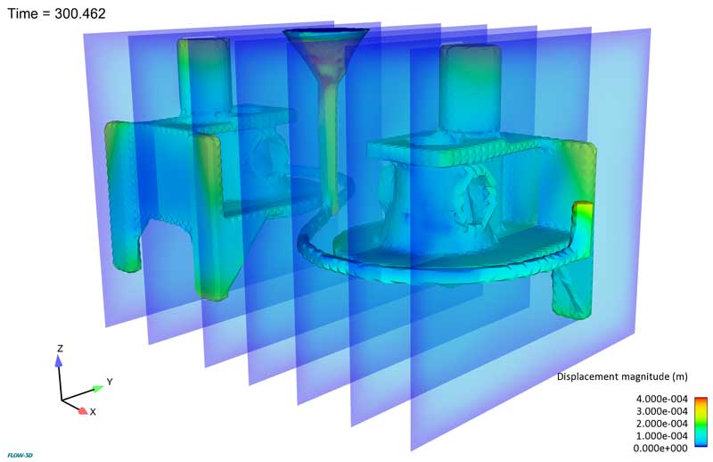
금형과 응고된 유체 표면 사이의 경계면에서 발생하는 응력이 부분적으로 결합되어 제한된 수축을 확인할 수 있습니다. 그림 4는 시뮬레이션을 통해 주형 부분의 변형과 다이 부분의 절반의 변형을 보여 줍니다. 온도가 감소함에 따라 다이 캐스트와 주물이 서로 다른 속도로 수축하여 간섭 영역에 큰 응력이 발생하고 잠재적인 문제 영역이 나타납니다. 다이와 부품에서 결합된 응력을 계산하면 사용자가 각 구성 요소 내에서 발생하는 응력을 더 잘 예측하고 부품 품질을 개선하고 도구 수명을 연장하는 방법에 대한 통찰력을 제공할 수 있습니다.
다른 단단한 물체들의 상호 작용은 현대 디자인과 공학의 중요한 부분입니다. FSI구성 요소와 TSE고정 유체 영역 간의 새로운 결합 옵션이 FLOW-3D에 추가되어 오늘날의 엔지니어들이 정기적으로 접하는 복잡한 기하학적 구조를 평가하는 데 유용한 도구가 되었습니다.

Microfluidics 모델링 , 그래디언트 생성 장치 시뮬레이션 및 검증 작업을 계속하는 것은 Flow Science의 최신 연구분야입니다. 확산 기반 그라디언트는 많은 복잡한 생물학적 과정에서 없어서는 안될 부분입니다. 한 예로 세포가 화학적 구배를 따라 이동하는 화학 주성 (chemotaxis )으로 인한 상처의 치료 방법입니다. 지난 몇 년 동안 확산 구배를 설정하고 연구하기 위한 다양한 접근법이 등장했지만 모두 문제 해결에 어려움을 겪고 있습니다.
Atencia 등은 이전 접근법의 알려진 문제점을 극복하기 위해 혁신적인 미세 유체 구배 생성기 (마이크로 유체 팔레트)를 제안했습니다.
확산 그라디언트를 설정하는 세 가지 주요 접근법으로 층류, 멤브레인 및 하이드로 겔 및 자유 확산 방법이 있으며 각각의 특징이 았습니다. 그러나, 언급한 것처럼 문제를 해결하는데 동반되는 어려움이 있습니다.
microfluidic 장치에서 그라디언트를 연구하고 확립하기 위한 표준 접근법은 층류의 사용을 포함합니다. 이 접근법은 매우 간단하지만 대류로 인해 전단 응력이 발생합니다. 전단 응력은 세포 반응을 변화시킬 수 있습니다. 예를 들어, 바이어스 된 세포 이동 및 비대칭 대량 수송이 발생할 수있습니다.
보다 최근의 개발은 강성 멤브레인 및 하이드로 겔을 사용하는 것을 포함하여 확산 구배를 설정하여 대류 흐름을 피하는 것입니다. 그러나 막과 겔은 확산 속도를 감소시켜 그라데이션의 일시적인 현상에 영향을줍니다.
마지막으로, 2 개의 유체 플러그를 접촉시켜 자유로운 확산을 가능하게 하는 접근법이 개발되었습니다. 그러나 이 접근 방식은 1-D 흐름에만 국한됩니다. 또한, 일단 그래디언트가 설정되면, 확산류 구배를 수정하기 위해 대류 흐름을 사용해야 하며, 이는 층류 유동에서 전단 응력 발생의 초기 문제로 되돌아갑니다.
여기에서는 Atencia 등이 제안한 확산성 구배 생성에 대한 새로운 접근법의 원리에 대해 논의하고 FLOW-3D 시뮬레이션 결과를 제시합니다.

Atencia 등이 제안한 미세 유체 팔레트의 디자인은 위에 나와 있습니다. 1-D의 경우, 대류 장치 1의 질량 균형은 입구 1과 출구 1의 유속을 일치 시키면 확산을 통해 전달을 허용하면서 주 마이크로 채널을 통한 흐름을 방지합니다. 대류 장치 1은 완벽한 소스 역할을 합니다. 2 차원의 경우는 2 차원 이상의 대류 단위가있는 1 차원의 경우를 단순히 확장한 것입니다.
아래의 1 차원 마이크로 유체 팔레트 애니메이션에서 주 중앙 마이크로 채널로부터의 대류 세포의 깨끗한 분리는 플롯 된 유선을 통해 볼 수 있습니다. 유선형은 모두 대류 단위에만 제한되며 단일 채널도 마이크로 채널로 누출되지 않아 대류와 확산의 탁월한 분리를 나타냅니다. 소스 농도의 진화는 플롯에서 볼 수 있습니다. 플롯은 애니메이션이 끝날 때까지 일정하게 보입니다.
2D 마이크로 유체 팔레트는 생성 된 그라데이션에 대한 시공간 제어를 보여줍니다. 소스와 싱크는 각속도로 회전합니다. 또한 매 초마다 활성 액세스 포트가 비활성화되고 다음 포트가 켜집니다. 챔버 내부의 확산 상태를 확인하기 위해 3 개의 라인 프로브가 시뮬레이션에 배치됩니다 (아래 시뮬레이션의 오른쪽 하단 창에서 각각 빨간색, 파란색 및 검은 색으로 표시됨).
2D 3D 마이크로 유체 팔레트의 FLOW-3D 시뮬레이션 결과.
FLOW-3D 결과는 챔버 내부의 농도 변화 측면에서 실험 결과와 잘 일치합니다. 아래 이미지는 실험 결과와 시뮬레이션 결과 모두에 대한 시간 스냅 샷을 보여줍니다. 실험 결과가 정규화되었습니다. 또한 실험은 형광 강도를 사용하여 소스의 농도를 나타냅니다. 시뮬레이션에서 FlowSight 의 라인 프로브는 3 개의 액세스 포트 사이의 농도를 연구하는 데 사용됩니다.
Atencia J, Morrow J, Locascio L.E., The microfluidic palette: A diffusive gradient generator with spatio-temporal control, The Royal Society of Chemistry 2009
Introduction
There is increasing interest in the lost foam casting technique because of its ability to produce near-net-shaped components of high complexity. The idea is to first make a prototype of the part to be cast in foam. This is then used as a pattern that can be placed in a box and surrounded by sand. Finally, metal is poured such that it smoothly replaces the foam by melting and/or evaporating it.
The stiffness of the foam makes it possible to cast parts having thin walls or other fine-scale features, and since the foam does not have to be removed at the end of the casting process, parts can be made that require fewer gaskets to assemble. Furthermore, because the foam pattern holds the sand (mold) in place there is little need to use binders in the sand, which means that the sand doesn’t have to be disposed of and can be used again. All these features make the lost foam process highly attractive to manufacturers.
Unfortunately, one rarely gets a free lunch and lost foam casting is no exception. For the process to be successful there must be a high degree of process control. Foams must have the proper characteristics and be coated with just the right material, and pouring sprues and gates for delivering metal to the mold must be carefully arranged. Metal pour temperatures must be sufficiently high to prevent premature solidification. And finally, the filling pattern of a mold should be such that metal fronts do not merge in a way that traps liquefied foam material, which could cause internal defects in the cast part.
To help casters address some of these difficult problems the computational fluid dynamics (CFD) program FLOW-3DÒ has been outfitted with special modeling capabilities to simulate the lost foam process. Using these models, it is possible to simulate the filling of a lost foam mold and the subsequent solidification of the metal. An extra feature in FLOW-3DÒ is the capability to predict where folds or other defects associated with trapped foam products are likely to be located.
The purpose of this paper is to demonstrate the usefulness and accuracy of lost foam predictions made with FLOW-3DÒ by presenting a direct comparison between experimental and computational results. The example chosen for this comparison is described in the next section. Subsequent sections present the comparisons with an emphasis on how the computational results can be used to understand why things happened as they did. This last point is most important, because it offers the user direct evidence and insight into how a casting could be improved.
[다운로드]
One of the unique features of FLOW-3Dr is the FAVORTM advantage used to accurately represent complex geometry in a rectangular Cartesian mesh.
The tedious work of generating a mesh for complex geometry is avoided. Due to this advantage, FLOW-3Dr can be used to simulate °ow in complex mi-crochannels accurately and e±ciently. Figure 1 shows a novel design of a microchannel with obliquely ori-ented or staggered herringbone ridges on its bottom wall to generate chaotic mixing of °uids (Stroock et al., Science, 295, 647-651, 2002). Fluid °ow and mix-ing through this device can be easily simulated with complicated geometry resolved using FAVOR TM. Fig-ure 2 displays the secondary °ow in two typical cross sections along the channel axis of this device. The predicted °ow ¯elds matches the experimental obser-vations of Stroock et al. very well.
[다운로드]
Applications of FLOW-3Dr to MEMS (Multiphysics Capabilities)
Background
From time to time it has been observed that large velocities may appear in the vicinity of grid elements that are severely, but not completely, blocked by solid obstacles. On some occasions these regions even exhibit an instability in which these velocities continue to grow with time. In this note the reason for these problems, or at least for some of these problems, is discussed and a solution is given.
Problems Associated with Abrupt Area Changes
Instabilities that sometimes arise in a flow solution can often be traced to locations where there is a large change in flow area across a grid element. For example, consider an element having a small area fraction on its left side and a full open area on its right side. When flow is moving fluid from the left to the right there is a large reduction in velocity at the right in order to have a conserved volume of flow (i.e., uA should be constant in the direction of flow, where A is the fractional area open at the side of an element). At the right side the velocity receives a larger advective flux from the left side than it should because no mechanism is in place to allow for an expansion of the flow between the left and right sides. To recover the correct velocity at the right side the pressure in the element must decrease more than it otherwise should. In some circumstances this decrease may then pull in a cross–flow that grows with time.
It is well known that there should be significant flow losses at abrupt area expansions and contractions. Such losses were never considered in the original development of the FAVOR™ method, so it is not surprising that their absence could cause some distortions in the flow. In the next section a brief discussion of flow losses is given, which is then followed by a proposed addition to the advective flow that aims to account for these losses.
[다운로드]
Overview
In free-surface flows the turbulence in the liquid may be sufficient to disturb the surface to the point of entraining air into the flow. This process is important, for example, in water treatment where air is needed to sustain microorganisms for water purification and in rivers and streams for sustaining a healthy fish population. Air entrainment is typically engineered into spillways downstream of hydropower plants to reduce the possibility of cavitation damage at the base of the spillway. Situations where air entrainment is undesirable are in the sprue and runner systems used by metal casters, and in the filling of liquid containers used for consumer products.
The importance of being able to predict the amount and distribution of entrained air at a free liquid surface has led to the development of a unique model in FLOW-3D®. The model has two options. One option, to be used when the volume fraction of entrained air is relatively low, uses a passive scalar variable to record and transport the air volume fraction. This model is passive in that it does not alter the dynamics of the flow.
The second air-entrainment model option is based on a variable density formulation. This model includes the “bulking” of fluid volume by the addition of air and the buoyancy effects associated with entrained air. This dynamically coupled model cannot, however, be used in conjunction with heat transport and natural (thermal) convection.
In addition, when using the variable density formulation, the model can include a relative drifting of air in water, the possible escape of air if it rises to the surface of the water and the removal or addition of air to trapped bubble regions represented as adiabatic bubbles.
The same basic entrainment process is used in both options. It is based on a competition between the stabilizing forces of gravity and surface tension and the destabilizing effects of surface turbulence.
Because turbulence is the main cause of entrainment, a turbulence-transport model must be used in connection with the air-entrainment model. It is recommended that the RNG version of the more traditional k-epsilon turbulence model be employed. All the validation tests reported in this Technical Note were performed using the RNG model.
[다운로드]
1. Introduction
The three-dimensional sediment scour model for non-cohesive soils was first introduced to FLOW-3D in Version 8.0 to simulate sediment erosion and deposition (Brethour, 2003). It was coupled with the three-dimensional fluid dynamics and considered entrainment, drifting and settling of sediment grains. In Version 9.4 the model was improved by introducing bedload transport and multiple sediment species (Brethour and Burnham, 2010). Although applications were successfully simulated, a major limitation of the model was the approximate treatment of the interface between the packed and suspended sediments. The packed bed was represented by scalars rather than FAVORTM (Fractional Area Volume Obstacle Representation, the standard treatment for solid components in FLOW-3D). As a result, limited information about the packed bed interface was available. That made accurate calculation of bed shear stress, a critical factor determining the model accuracy, challenging.
In this work, the 3D sediment scour model is mostly redeveloped and rewritten. The model is still fully coupled with fluid flow, allows multiple non-cohesive species and considers entrainment, deposition, bedload transport and suspended load transport. The fundamental difference from the old model is that the packed bed is described by the FAVORTM technique. At each time step, area and volume fractions describing the packed sediments are calculated throughout the domain. In the mesh cells at the bed interface, the location, orientation and area of the interface are calculated and used to determine the bed shear stress, the critical Shields parameter, the erosion rate and the bedload transport rate. Bed shear stress is evaluated using the standard wall function with consideration of bed surface roughness that is related to the median grain size d50. A sub-mesh method is developed and implemented to calculate bedload transport. Computation of erosion considers entrainment and deposition simultaneously in addition to bedload transport.
Furthermore, a shallow-water sediment scour model is developed in this work by adapting the new 3D model. It is coupled with the 2D shallow water flows to calculate depth-averaged properties for both suspended and packed sediments. Its main differences from the 3D model are 1) the settling velocity of grains is calculated using an existing equation instead of the drift-flux approach in the 3D model, and 2) turbulent bed shear stress is calculated using a well-accepted quadratic law rather than the log wall function. The drag coefficient for the bed shear stress is either user-given or locally evaluated using the water depth and the bed surface roughness that is proportional to d50 of the bed material. The following sections present the sediment theory used in the model and application and validation cases.
Introduction
A recent effort to compare the performance of four commercial computational fluid dynamics (CFD) software packages for microfluidic applications (T. Glatzel, 2008) was recently brought to the attention of the staff at Flow Science, Inc. The paper reported simulation results from the four CFD packages for a set of flow problems typically encountered in microfluidics. The intent of the paper was to compare the quality of the solvers by removing differentiating features (meshing, special numerical algorithms, etc.) from the analysis. While we acknowledge the worthiness and difficulty of the task, we believe there are some significant limitations to the usefulness of the comparisons made in the paper.
To begin, the modeling restrictions employed prevented the individual software programs from making use of particular options they might have for obtaining better simulations of particular flow problems. A second point, at least in connection with our software product, FLOW-3D®, we have noted numerous inaccuracies in the software’s description, an incorrect use of boundary conditions and several other failures to operate the software properly. This note is intended to correct these deficiencies and omissions as well as to present a repetition of the computational examples, as near as possible, from data given in the original paper. It will be shown that FLOW-3D® performs all the comparison problems as well or better than other software tools included in the original study.
Introduction
Dissolution of salt in liquid is of interest in several applications – from solution mining to food processing to medical applications. This article describes a new model in FLOW-3D1 version 10.0 for dissolving salt in fluids and tracking the solute in the brine.
The dissolution of salt increases the density of the fluid and thus may affect the flow. In addition, as salt is dissolved, the flow domain increases. It is of interest, therefore, to predict these changes in the flow as well as the transport of the dissolved salt in the fluid.
The model accounts for the basic physical phenomena, such as mass transfer at the interface between salt and fluid, the change of volume and shape of the solid salt, diffusion and convection of dissolved salt in fluid and, finally, the change in fluid density, viscosity and surface tension coefficient.
Introduction
There is frequently a need to have a faster way to generate a steady free-surface flow than by simply trying to compute the asymptotic state of a transient flow. The situation is similar to solving for incompressible flow by trying to use a compressible flow solver. In the latter case, compression waves can take an extremely long time to decay and leave a resultant “incompressible” flow. Correspondingly, in free-surface flows the fluid is incompressible, but surface waves may require a very long time to damp out to produce a steady surface configuration.
Overview
In fluids composed of multiple components, e.g., fluid/particles, fluid/bubbles, fluid/fluid mixtures, where the components have different densities, it is observed that the components can assume different flow velocities. Velocity differences arise because the density differences result in non-uniform body forces. Often the differences in velocities can be very pronounced, for example, large raindrops falling through air or gravel sinking in water. Under many conditions, however, the relative velocities are small enough to be described as a “drift” of one component through the other. Examples are dust in air and silt in water.
The “drift” distinction has to do with whether or not the inertia of a dispersed component moving in a continuous component is significant. If the inertia of relative motion can be ignored, and the relative velocity reduced to a balance between a driving force (say gravity or a pressure gradient) and an opposing drag force between the components, then we can speak of a “drift-flux” approximation. Drift velocities are primarily responsible for the transport of mass and energy. Some momentum may be transported as well, but this is usually quite small and has been neglected in the FLOW-3D1 drift model. A more complete analysis of when the “drift” assumption is valid can be found in the Flow Science, Inc.