Lab-on-a-Chip 시스템의 혈류 역학에 대한 검토: 엔지니어링 관점

Review on Blood Flow Dynamics in Lab-on-a-Chip Systems: An Engineering Perspective

  • Bin-Jie Lai
  • Li-Tao Zhu
  • Zhe Chen*
  • Bo Ouyang*
  • , and 
  • Zheng-Hong Luo*

Abstract

다양한 수송 메커니즘 하에서, “LOC(lab-on-a-chip)” 시스템에서 유동 전단 속도 조건과 밀접한 관련이 있는 혈류 역학은 다양한 수송 현상을 초래하는 것으로 밝혀졌습니다.

본 연구는 적혈구의 동적 혈액 점도 및 탄성 거동과 같은 점탄성 특성의 역할을 통해 LOC 시스템의 혈류 패턴을 조사합니다. 모세관 및 전기삼투압의 주요 매개변수를 통해 LOC 시스템의 혈액 수송 현상에 대한 연구는 실험적, 이론적 및 수많은 수치적 접근 방식을 통해 제공됩니다.

전기 삼투압 점탄성 흐름에 의해 유발되는 교란은 특히 향후 연구 기회를 위해 혈액 및 기타 점탄성 유체를 취급하는 LOC 장치의 혼합 및 분리 기능 향상에 논의되고 적용됩니다. 또한, 본 연구는 보다 정확하고 단순화된 혈류 모델에 대한 요구와 전기역학 효과 하에서 점탄성 유체 흐름에 대한 수치 연구에 대한 강조와 같은 LOC 시스템 하에서 혈류 역학의 수치 모델링의 문제를 식별합니다.

전기역학 현상을 연구하는 동안 제타 전위 조건에 대한 보다 실용적인 가정도 강조됩니다. 본 연구는 모세관 및 전기삼투압에 의해 구동되는 미세유체 시스템의 혈류 역학에 대한 포괄적이고 학제적인 관점을 제공하는 것을 목표로 한다.

KEYWORDS: 

1. Introduction

1.1. Microfluidic Flow in Lab-on-a-Chip (LOC) Systems

Over the past several decades, the ability to control and utilize fluid flow patterns at microscales has gained considerable interest across a myriad of scientific and engineering disciplines, leading to growing interest in scientific research of microfluidics. 

(1) Microfluidics, an interdisciplinary field that straddles physics, engineering, and biotechnology, is dedicated to the behavior, precise control, and manipulation of fluids geometrically constrained to a small, typically submillimeter, scale. 

(2) The engineering community has increasingly focused on microfluidics, exploring different driving forces to enhance working fluid transport, with the aim of accurately and efficiently describing, controlling, designing, and applying microfluidic flow principles and transport phenomena, particularly for miniaturized applications. 

(3) This attention has chiefly been fueled by the potential to revolutionize diagnostic and therapeutic techniques in the biomedical and pharmaceutical sectorsUnder various driving forces in microfluidic flows, intriguing transport phenomena have bolstered confidence in sustainable and efficient applications in fields such as pharmaceutical, biochemical, and environmental science. The “lab-on-a-chip” (LOC) system harnesses microfluidic flow to enable fluid processing and the execution of laboratory tasks on a chip-sized scale. LOC systems have played a vital role in the miniaturization of laboratory operations such as mixing, chemical reaction, separation, flow control, and detection on small devices, where a wide variety of fluids is adapted. Biological fluid flow like blood and other viscoelastic fluids are notably studied among the many working fluids commonly utilized by LOC systems, owing to the optimization in small fluid sample volumed, rapid response times, precise control, and easy manipulation of flow patterns offered by the system under various driving forces. 

(4)The driving forces in blood flow can be categorized as passive or active transport mechanisms and, in some cases, both. Under various transport mechanisms, the unique design of microchannels enables different functionalities in driving, mixing, separating, and diagnosing blood and drug delivery in the blood. 

(5) Understanding and manipulating these driving forces are crucial for optimizing the performance of a LOC system. Such knowledge presents the opportunity to achieve higher efficiency and reliability in addressing cellular level challenges in medical diagnostics, forensic studies, cancer detection, and other fundamental research areas, for applications of point-of-care (POC) devices. 

(6)

1.2. Engineering Approach of Microfluidic Transport Phenomena in LOC Systems

Different transport mechanisms exhibit unique properties at submillimeter length scales in microfluidic devices, leading to significant transport phenomena that differ from those of macroscale flows. An in-depth understanding of these unique transport phenomena under microfluidic systems is often required in fluidic mechanics to fully harness the potential functionality of a LOC system to obtain systematically designed and precisely controlled transport of microfluids under their respective driving force. Fluid mechanics is considered a vital component in chemical engineering, enabling the analysis of fluid behaviors in various unit designs, ranging from large-scale reactors to separation units. Transport phenomena in fluid mechanics provide a conceptual framework for analytically and descriptively explaining why and how experimental results and physiological phenomena occur. The Navier–Stokes (N–S) equation, along with other governing equations, is often adapted to accurately describe fluid dynamics by accounting for pressure, surface properties, velocity, and temperature variations over space and time. In addition, limiting factors and nonidealities for these governing equations should be considered to impose corrections for empirical consistency before physical models are assembled for more accurate controls and efficiency. Microfluidic flow systems often deviate from ideal conditions, requiring adjustments to the standard governing equations. These deviations could arise from factors such as viscous effects, surface interactions, and non-Newtonian fluid properties from different microfluid types and geometrical layouts of microchannels. Addressing these nonidealities supports the refining of theoretical models and prediction accuracy for microfluidic flow behaviors.

The analytical calculation of coupled nonlinear governing equations, which describes the material and energy balances of systems under ideal conditions, often requires considerable computational efforts. However, advancements in computation capabilities, cost reduction, and improved accuracy have made numerical simulations using different numerical and modeling methods a powerful tool for effectively solving these complex coupled equations and modeling various transport phenomena. Computational fluid dynamics (CFD) is a numerical technique used to investigate the spatial and temporal distribution of various flow parameters. It serves as a critical approach to provide insights and reasoning for decision-making regarding the optimal designs involving fluid dynamics, even prior to complex physical model prototyping and experimental procedures. The integration of experimental data, theoretical analysis, and reliable numerical simulations from CFD enables systematic variation of analytical parameters through quantitative analysis, where adjustment to delivery of blood flow and other working fluids in LOC systems can be achieved.

Numerical methods such as the Finite-Difference Method (FDM), Finite-Element-Method (FEM), and Finite-Volume Method (FVM) are heavily employed in CFD and offer diverse approaches to achieve discretization of Eulerian flow equations through filling a mesh of the flow domain. A more in-depth review of numerical methods in CFD and its application for blood flow simulation is provided in Section 2.2.2.

1.3. Scope of the Review

In this Review, we explore and characterize the blood flow phenomena within the LOC systems, utilizing both physiological and engineering modeling approaches. Similar approaches will be taken to discuss capillary-driven flow and electric-osmotic flow (EOF) under electrokinetic phenomena as a passive and active transport scheme, respectively, for blood transport in LOC systems. Such an analysis aims to bridge the gap between physical (experimental) and engineering (analytical) perspectives in studying and manipulating blood flow delivery by different driving forces in LOC systems. Moreover, the Review hopes to benefit the interests of not only blood flow control in LOC devices but also the transport of viscoelastic fluids, which are less studied in the literature compared to that of Newtonian fluids, in LOC systems.

Section 2 examines the complex interplay between viscoelastic properties of blood and blood flow patterns under shear flow in LOC systems, while engineering numerical modeling approaches for blood flow are presented for assistance. Sections 3 and 4 look into the theoretical principles, numerical governing equations, and modeling methodologies for capillary driven flow and EOF in LOC systems as well as their impact on blood flow dynamics through the quantification of key parameters of the two driving forces. Section 5 concludes the characterized blood flow transport processes in LOC systems under these two forces. Additionally, prospective areas of research in improving the functionality of LOC devices employing blood and other viscoelastic fluids and potentially justifying mechanisms underlying microfluidic flow patterns outside of LOC systems are presented. Finally, the challenges encountered in the numerical studies of blood flow under LOC systems are acknowledged, paving the way for further research.

2. Blood Flow Phenomena

ARTICLE SECTIONS

Jump To


2.1. Physiological Blood Flow Behavior

Blood, an essential physiological fluid in the human body, serves the vital role of transporting oxygen and nutrients throughout the body. Additionally, blood is responsible for suspending various blood cells including erythrocytes (red blood cells or RBCs), leukocytes (white blood cells), and thrombocytes (blood platelets) in a plasma medium.Among the cells mentioned above, red blood cells (RBCs) comprise approximately 40–45% of the volume of healthy blood. 

(7) An RBC possesses an inherent elastic property with a biconcave shape of an average diameter of 8 μm and a thickness of 2 μm. This biconcave shape maximizes the surface-to-volume ratio, allowing RBCs to endure significant distortion while maintaining their functionality. 

(8,9) Additionally, the biconcave shape optimizes gas exchange, facilitating efficient uptake of oxygen due to the increased surface area. The inherent elasticity of RBCs allows them to undergo substantial distortion from their original biconcave shape and exhibits high flexibility, particularly in narrow channels.RBC deformability enables the cell to deform from a biconcave shape to a parachute-like configuration, despite minor differences in RBC shape dynamics under shear flow between initial cell locations. As shown in Figure 1(a), RBCs initiating with different resting shapes and orientations displaying display a similar deformation pattern 

(10) in terms of its shape. Shear flow induces an inward bending of the cell at the rear position of the rim to the final bending position, 

(11) resulting in an alignment toward the same position of the flow direction.

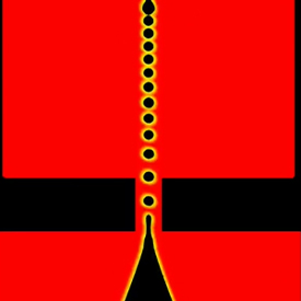
Figure 1. Images of varying deformation of RBCs and different dynamic blood flow behaviors. (a) The deforming shape behavior of RBCs at four different initiating positions under the same experimental conditions of a flow from left to right, (10) (b) RBC aggregation, (13) (c) CFL region. (18) Reproduced with permission from ref (10). Copyright 2011 Elsevier. Reproduced with permission from ref (13). Copyright 2022 The Authors, under the terms of the Creative Commons (CC BY 4.0) License https://creativecommons.org/licenses/by/4.0/. Reproduced with permission from ref (18). Copyright 2019 Elsevier.

The flexible property of RBCs enables them to navigate through narrow capillaries and traverse a complex network of blood vessels. The deformability of RBCs depends on various factors, including the channel geometry, RBC concentration, and the elastic properties of the RBC membrane. 

(12) Both flexibility and deformability are vital in the process of oxygen exchange among blood and tissues throughout the body, allowing cells to flow in vessels even smaller than the original cell size prior to deforming.As RBCs serve as major components in blood, their collective dynamics also hugely affect blood rheology. RBCs exhibit an aggregation phenomenon due to cell to cell interactions, such as adhesion forces, among populated cells, inducing unique blood flow patterns and rheological behaviors in microfluidic systems. For blood flow in large vessels between a diameter of 1 and 3 cm, where shear rates are not high, a constant viscosity and Newtonian behavior for blood can be assumed. However, under low shear rate conditions (0.1 s

–1) in smaller vessels such as the arteries and venules, which are within a diameter of 0.2 mm to 1 cm, blood exhibits non-Newtonian properties, such as shear-thinning viscosity and viscoelasticity due to RBC aggregation and deformability. The nonlinear viscoelastic property of blood gives rise to a complex relationship between viscosity and shear rate, primarily influenced by the highly elastic behavior of RBCs. A wide range of research on the transient behavior of the RBC shape and aggregation characteristics under varied flow circumstances has been conducted, aiming to obtain a better understanding of the interaction between blood flow shear forces from confined flows.

For a better understanding of the unique blood flow structures and rheological behaviors in microfluidic systems, some blood flow patterns are introduced in the following section.

2.1.1. RBC Aggregation

RBC aggregation is a vital phenomenon to be considered when designing LOC devices due to its impact on the viscosity of the bulk flow. Under conditions of low shear rate, such as in stagnant or low flow rate regions, RBCs tend to aggregate, forming structures known as rouleaux, resembling stacks of coins as shown in Figure 1(b). 

(13) The aggregation of RBCs increases the viscosity at the aggregated region, 

(14) hence slowing down the overall blood flow. However, when exposed to high shear rates, RBC aggregates disaggregate. As shear rates continue to increase, RBCs tend to deform, elongating and aligning themselves with the direction of the flow. 

(15) Such a dynamic shift in behavior from the cells in response to the shear rate forms the basis of the viscoelastic properties observed in whole blood. In essence, the viscosity of the blood varies according to the shear rate conditions, which are related to the velocity gradient of the system. It is significant to take the intricate relationship between shear rate conditions and the change of blood viscosity due to RBC aggregation into account since various flow driving conditions may induce varied effects on the degree of aggregation.

2.1.2. Fåhræus-Lindqvist Effect

The Fåhræus–Lindqvist (FL) effect describes the gradual decrease in the apparent viscosity of blood as the channel diameter decreases. 

(16) This effect is attributed to the migration of RBCs toward the central region in the microchannel, where the flow rate is higher, due to the presence of higher pressure and asymmetric distribution of shear forces. This migration of RBCs, typically observed at blood vessels less than 0.3 mm, toward the higher flow rate region contributes to the change in blood viscosity, which becomes dependent on the channel size. Simultaneously, the increase of the RBC concentration in the central region of the microchannel results in the formation of a less viscous region close to the microchannel wall. This region called the Cell-Free Layer (CFL), is primarily composed of plasma. 

(17) The combination of the FL effect and the following CFL formation provides a unique phenomenon that is often utilized in passive and active plasma separation mechanisms, involving branched and constriction channels for various applications in plasma separation using microfluidic systems.

2.1.3. Cell-Free Layer Formation

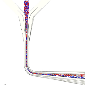
In microfluidic blood flow, RBCs form aggregates at the microchannel core and result in a region that is mostly devoid of RBCs near the microchannel walls, as shown in Figure 1(c). 

(18) The region is known as the cell-free layer (CFL). The CFL region is often known to possess a lower viscosity compared to other regions within the blood flow due to the lower viscosity value of plasma when compared to that of the aggregated RBCs. Therefore, a thicker CFL region composed of plasma correlates to a reduced apparent whole blood viscosity. 

(19) A thicker CFL region is often established following the RBC aggregation at the microchannel core under conditions of decreasing the tube diameter. Apart from the dependence on the RBC concentration in the microchannel core, the CFL thickness is also affected by the volume concentration of RBCs, or hematocrit, in whole blood, as well as the deformability of RBCs. Given the influence CFL thickness has on blood flow rheological parameters such as blood flow rate, which is strongly dependent on whole blood viscosity, investigating CFL thickness under shear flow is crucial for LOC systems accounting for blood flow.

2.1.4. Plasma Skimming in Bifurcation Networks

The uneven arrangement of RBCs in bifurcating microchannels, commonly termed skimming bifurcation, arises from the axial migration of RBCs within flowing streams. This uneven distribution contributes to variations in viscosity across differing sizes of bifurcating channels but offers a stabilizing effect. Notably, higher flow rates in microchannels are associated with increased hematocrit levels, resulting in higher viscosity compared with those with lower flow rates. Parametric investigations on bifurcation angle, 

(20) thickness of the CFL, 

(21) and RBC dynamics, including aggregation and deformation, 

(22) may alter the varying viscosity of blood and its flow behavior within microchannels.

2.2. Modeling on Blood Flow Dynamics

2.2.1. Blood Properties and Mathematical Models of Blood Rheology

Under different shear rate conditions in blood flow, the elastic characteristics and dynamic changes of the RBC induce a complex velocity and stress relationship, resulting in the incompatibility of blood flow characterization through standard presumptions of constant viscosity used for Newtonian fluid flow. Blood flow is categorized as a viscoelastic non-Newtonian fluid flow where constitutive equations governing this type of flow take into consideration the nonlinear viscometric properties of blood. To mathematically characterize the evolving blood viscosity and the relationship between the elasticity of RBC and the shear blood flow, respectively, across space and time of the system, a stress tensor (τ) defined by constitutive models is often coupled in the Navier–Stokes equation to account for the collective impact of the constant dynamic viscosity (η) and the elasticity from RBCs on blood flow.The dynamic viscosity of blood is heavily dependent on the shear stress applied to the cell and various parameters from the blood such as hematocrit value, plasma viscosity, mechanical properties of the RBC membrane, and red blood cell aggregation rate. The apparent blood viscosity is considered convenient for the characterization of the relationship between the evolving blood viscosity and shear rate, which can be defined by Casson’s law, as shown in eq 1.

𝜇=𝜏0𝛾˙+2𝜂𝜏0𝛾˙⎯⎯⎯⎯⎯⎯⎯√+𝜂�=�0�˙+2��0�˙+�

(1)where τ

0 is the yield stress–stress required to initiate blood flow motion, η is the Casson rheological constant, and γ̇ is the shear rate. The value of Casson’s law parameters under blood with normal hematocrit level can be defined as τ

0 = 0.0056 Pa and η = 0.0035 Pa·s. 

(23) With the known property of blood and Casson’s law parameters, an approximation can be made to the dynamic viscosity under various flow condition domains. The Power Law model is often employed to characterize the dynamic viscosity in relation to the shear rate, since precise solutions exist for specific geometries and flow circumstances, acting as a fundamental standard for definition. The Carreau and Carreau–Yasuda models can be advantageous over the Power Law model due to their ability to evaluate the dynamic viscosity at low to zero shear rate conditions. However, none of the above-mentioned models consider the memory or other elastic behavior of blood and its RBCs. Some other commonly used mathematical models and their constants for the non-Newtonian viscosity property characterization of blood are listed in Table 1 below. 

(24−26)Table 1. Comparison of Various Non-Newtonian Models for Blood Viscosity 

(24−26)

ModelNon-Newtonian ViscosityParameters
Power Law(2)n = 0.61, k = 0.42
Carreau(3)μ0 = 0.056 Pa·s, μ = 0.00345 Pa·s, λ = 3.1736 s, m = 2.406, a = 0.254
Walburn–Schneck(4)C1 = 0.000797 Pa·s, C2 = 0.0608 Pa·s, C3 = 0.00499, C4 = 14.585 g–1, TPMA = 25 g/L
Carreau–Yasuda(5)μ0 = 0.056 Pa·s, μ = 0.00345 Pa·s, λ = 1.902 s, n = 0.22, a = 1.25
Quemada(6)μp = 0.0012 Pa·s, k = 2.07, k0 = 4.33, γ̇c = 1.88 s–1

The blood rheology is commonly known to be influenced by two key physiological factors, namely, the hematocrit value (H

t) and the fibrinogen concentration (c

f), with an average value of 42% and 0.252 gd·L

–1, respectively. Particularly in low shear conditions, the presence of varying fibrinogen concentrations affects the tendency for aggregation and rouleaux formation, while the occurrence of aggregation is contingent upon specific levels of hematocrit. 

(27) The study from Apostolidis et al. 

(28) modifies the Casson model through emphasizing its reliance on hematocrit and fibrinogen concentration parameter values, owing to the extensive knowledge of the two physiological blood parameters.The viscoelastic response of blood is heavily dependent on the elasticity of the RBC, which is defined by the relationship between the deformation and stress relaxation from RBCs under a specific location of shear flow as a function of the velocity field. The stress tensor is usually characterized by constitutive equations such as the Upper-Convected Maxwell Model 

(29) and the Oldroyd-B model 

(30) to track the molecule effects under shear from different driving forces. The prominent non-Newtonian features, such as shear thinning and yield stress, have played a vital role in the characterization of blood rheology, particularly with respect to the evaluation of yield stress under low shear conditions. The nature of stress measurement in blood, typically on the order of 1 mPa, is challenging due to its low magnitude. The occurrence of the CFL complicates the measurement further due to the significant decrease in apparent viscosity near the wall over time and a consequential disparity in viscosity compared to the bulk region.In addition to shear thinning viscosity and yield stress, the formation of aggregation (rouleaux) from RBCs under low shear rates also contributes to the viscoelasticity under transient flow 

(31) and thixotropy 

(32) of whole blood. Given the difficulty in evaluating viscoelastic behavior of blood under low strain magnitudes and limitations in generalized Newtonian models, the utilization of viscoelastic models is advocated to encompass elasticity and delineate non-shear components within the stress tensor. Extending from the Oldroyd-B model, Anand et al. 

(33) developed a viscoelastic model framework for adapting elasticity within blood samples and predicting non-shear stress components. However, to also address the thixotropic effects, the model developed by Horner et al. 

(34) serves as a more comprehensive approach than the viscoelastic model from Anand et al. Thixotropy 

(32) typically occurs from the structural change of the rouleaux, where low shear rate conditions induce rouleaux formation. Correspondingly, elasticity increases, while elasticity is more representative of the isolated RBCs, under high shear rate conditions. The model of Horner et al. 

(34) considers the contribution of rouleaux to shear stress, taking into account factors such as the characteristic time for Brownian aggregation, shear-induced aggregation, and shear-induced breakage. Subsequent advancements in the model from Horner et al. often revolve around refining the three aforementioned key terms for a more substantial characterization of rouleaux dynamics. Notably, this has led to the recently developed mHAWB model 

(35) and other model iterations to enhance the accuracy of elastic and viscoelastic contributions to blood rheology, including the recently improved model suggested by Armstrong et al. 

(36)

2.2.2. Numerical Methods (FDM, FEM, FVM)

Numerical simulation has become increasingly more significant in analyzing the geometry, boundary layers of flow, and nonlinearity of hyperbolic viscoelastic flow constitutive equations. CFD is a powerful and efficient tool utilizing numerical methods to solve the governing hydrodynamic equations, such as the Navier–Stokes (N–S) equation, continuity equation, and energy conservation equation, for qualitative evaluation of fluid motion dynamics under different parameters. CFD overcomes the challenge of analytically solving nonlinear forms of differential equations by employing numerical methods such as the Finite-Difference Method (FDM), Finite-Element Method (FEM), and Finite-Volume Method (FVM) to discretize and solve the partial differential equations (PDEs), allowing for qualitative reproduction of transport phenomena and experimental observations. Different numerical methods are chosen to cope with various transport systems for optimization of the accuracy of the result and control of error during the discretization process.FDM is a straightforward approach to discretizing PDEs, replacing the continuum representation of equations with a set of finite-difference equations, which is typically applied to structured grids for efficient implementation in CFD programs. 

(37) However, FDM is often limited to simple geometries such as rectangular or block-shaped geometries and struggles with curved boundaries. In contrast, FEM divides the fluid domain into small finite grids or elements, approximating PDEs through a local description of physics. 

(38) All elements contribute to a large, sparse matrix solver. However, FEM may not always provide accurate results for systems involving significant deformation and aggregation of particles like RBCs due to large distortion of grids. 

(39) FVM evaluates PDEs following the conservation laws and discretizes the selected flow domain into small but finite size control volumes, with each grid at the center of a finite volume. 

(40) The divergence theorem allows the conversion of volume integrals of PDEs with divergence terms into surface integrals of surface fluxes across cell boundaries. Due to its conservation property, FVM offers efficient outcomes when dealing with PDEs that embody mass, momentum, and energy conservation principles. Furthermore, widely accessible software packages like the OpenFOAM toolbox 

(41) include a viscoelastic solver, making it an attractive option for viscoelastic fluid flow modeling. 

(42)

2.2.3. Modeling Methods of Blood Flow Dynamics

The complexity in the blood flow simulation arises from deformability and aggregation that RBCs exhibit during their interaction with neighboring cells under different shear rate conditions induced by blood flow. Numerical models coupled with simulation programs have been applied as a groundbreaking method to predict such unique rheological behavior exhibited by RBCs and whole blood. The conventional approach of a single-phase flow simulation is often applied to blood flow simulations within large vessels possessing a moderate shear rate. However, such a method assumes the properties of plasma, RBCs and other cellular components to be evenly distributed as average density and viscosity in blood, resulting in the inability to simulate the mechanical dynamics, such as RBC aggregation under high-shear flow field, inherent in RBCs. To accurately describe the asymmetric distribution of RBC and blood flow, multiphase flow simulation, where numerical simulations of blood flows are often modeled as two immiscible phases, RBCs and blood plasma, is proposed. A common assumption is that RBCs exhibit non-Newtonian behavior while the plasma is treated as a continuous Newtonian phase.Numerous multiphase numerical models have been proposed to simulate the influence of RBCs on blood flow dynamics by different assumptions. In large-scale simulations (above the millimeter range), continuum-based methods are wildly used due to their lower computational demands. 

(43) Eulerian multiphase flow simulations offer the solution of a set of conservation equations for each separate phase and couple the phases through common pressure and interphase exchange coefficients. Xu et al. 

(44) utilized the combined finite-discrete element method (FDEM) to replicate the dynamic behavior and distortion of RBCs subjected to fluidic forces, utilizing the Johnson–Kendall–Roberts model 

(45) to define the adhesive forces of cell-to-cell interactions. The iterative direct-forcing immersed boundary method (IBM) is commonly employed in simulations of the fluid–cell interface of blood. This method effectively captures the intricacies of the thin and flexible RBC membranes within various external flow fields. 

(46) The study by Xu et al. 

(44) also adopts this approach to bridge the fluid dynamics and RBC deformation through IBM. Yoon and You utilized the Maxwell model to define the viscosity of the RBC membrane. 

(47) It was discovered that the Maxwell model could represent the stress relaxation and unloading processes of the cell. Furthermore, the reduced flexibility of an RBC under particular situations such as infection is specified, which was unattainable by the Kelvin–Voigt model 

(48) when compared to the Maxwell model in the literature. The Yeoh hyperplastic material model was also adapted to predict the nonlinear elasticity property of RBCs with FEM employed to discretize the RBC membrane using shell-type elements. Gracka et al. 

(49) developed a numerical CFD model with a finite-volume parallel solver for multiphase blood flow simulation, where an updated Maxwell viscoelasticity model and a Discrete Phase Model are adopted. In the study, the adapted IBM, based on unstructured grids, simulates the flow behavior and shape change of the RBCs through fluid-structure coupling. It was found that the hybrid Euler–Lagrange (E–L) approach 

(50) for the development of the multiphase model offered better results in the simulated CFL region in the microchannels.To study the dynamics of individual behaviors of RBCs and the consequent non-Newtonian blood flow, cell-shape-resolved computational models are often adapted. The use of the boundary integral method has become prevalent in minimizing computational expenses, particularly in the exclusive determination of fluid velocity on the surfaces of RBCs, incorporating the option of employing IBM or particle-based techniques. The cell-shaped-resolved method has enabled an examination of cell to cell interactions within complex ambient or pulsatile flow conditions 

(51) surrounding RBC membranes. Recently, Rydquist et al. 

(52) have looked to integrate statistical information from macroscale simulations to obtain a comprehensive overview of RBC behavior within the immediate proximity of the flow through introduction of respective models characterizing membrane shape definition, tension, bending stresses of RBC membranes.At a macroscopic scale, continuum models have conventionally been adapted for assessing blood flow dynamics through the application of elasticity theory and fluid dynamics. However, particle-based methods are known for their simplicity and adaptability in modeling complex multiscale fluid structures. Meshless methods, such as the boundary element method (BEM), smoothed particle hydrodynamics (SPH), and dissipative particle dynamics (DPD), are often used in particle-based characterization of RBCs and the surrounding fluid. By representing the fluid as discrete particles, meshless methods provide insights into the status and movement of the multiphase fluid. These methods allow for the investigation of cellular structures and microscopic interactions that affect blood rheology. Non-confronting mesh methods like IBM can also be used to couple a fluid solver such as FEM, FVM, or the Lattice Boltzmann Method (LBM) through membrane representation of RBCs. In comparison to conventional CFD methods, LBM has been viewed as a favorable numerical approach for solving the N–S equations and the simulation of multiphase flows. LBM exhibits the notable advantage of being amenable to high-performance parallel computing environments due to its inherently local dynamics. In contrast to DPD and SPH where RBC membranes are modeled as physically interconnected particles, LBM employs the IBM to account for the deformation dynamics of RBCs 

(53,54) under shear flows in complex channel geometries. 

(54,55) However, it is essential to acknowledge that the utilization of LBM in simulating RBC flows often entails a significant computational overhead, being a primary challenge in this context. Krüger et al. 

(56) proposed utilizing LBM as a fluid solver, IBM to couple the fluid and FEM to compute the response of membranes to deformation under immersed fluids. This approach decouples the fluid and membranes but necessitates significant computational effort due to the requirements of both meshes and particles.Despite the accuracy of current blood flow models, simulating complex conditions remains challenging because of the high computational load and cost. Balachandran Nair et al. 

(57) suggested a reduced order model of RBC under the framework of DEM, where the RBC is represented by overlapping constituent rigid spheres. The Morse potential force is adapted to account for the RBC aggregation exhibited by cell to cell interactions among RBCs at different distances. Based upon the IBM, the reduced-order RBC model is adapted to simulate blood flow transport for validation under both single and multiple RBCs with a resolved CFD-DEM solver. 

(58) In the resolved CFD-DEM model, particle sizes are larger than the grid size for a more accurate computation of the surrounding flow field. A continuous forcing approach is taken to describe the momentum source of the governing equation prior to discretization, which is different from a Direct Forcing Method (DFM). 

(59) As no body-conforming moving mesh is required, the continuous forcing approach offers lower complexity and reduced cost when compared to the DFM. Piquet et al. 

(60) highlighted the high complexity of the DFM due to its reliance on calculating an additional immersed boundary flux for the velocity field to ensure its divergence-free condition.The fluid–structure interaction (FSI) method has been advocated to connect the dynamic interplay of RBC membranes and fluid plasma within blood flow such as the coupling of continuum–particle interactions. However, such methodology is generally adapted for anatomical configurations such as arteries 

(61,62) and capillaries, 

(63) where both the structural components and the fluid domain undergo substantial deformation due to the moving boundaries. Due to the scope of the Review being blood flow simulation within microchannels of LOC devices without deformable boundaries, the Review of the FSI method will not be further carried out.In general, three numerical methods are broadly used: mesh-based, particle-based, and hybrid mesh–particle techniques, based on the spatial scale and the fundamental numerical approach, mesh-based methods tend to neglect the effects of individual particles, assuming a continuum and being efficient in terms of time and cost. However, the particle-based approach highlights more of the microscopic and mesoscopic level, where the influence of individual RBCs is considered. A review from Freund et al. 

(64) addressed the three numerical methodologies and their respective modeling approaches of RBC dynamics. Given the complex mechanics and the diverse levels of study concerning numerical simulations of blood and cellular flow, a broad spectrum of numerical methods for blood has been subjected to extensive review. 

(64−70) Ye at al. 

(65) offered an extensive review of the application of the DPD, SPH, and LBM for numerical simulations of RBC, while Rathnayaka et al. 

(67) conducted a review of the particle-based numerical modeling for liquid marbles through drawing parallels to the transport of RBCs in microchannels. A comparative analysis between conventional CFD methods and particle-based approaches for cellular and blood flow dynamic simulation can be found under the review by Arabghahestani et al. 

(66) Literature by Li et al. 

(68) and Beris et al. 

(69) offer an overview of both continuum-based models at micro/macroscales and multiscale particle-based models encompassing various length and temporal dimensions. Furthermore, these reviews deliberate upon the potential of coupling continuum-particle methods for blood plasma and RBC modeling. Arciero et al. 

(70) investigated various modeling approaches encompassing cellular interactions, such as cell to cell or plasma interactions and the individual cellular phases. A concise overview of the reviews is provided in Table 2 for reference.

Table 2. List of Reviews for Numerical Approaches Employed in Blood Flow Simulation

ReferenceNumerical methods
Li et al. (2013) (68)Continuum-based modeling (BIM), particle-based modeling (LBM, LB-FE, SPH, DPD)
Freund (2014) (64)RBC dynamic modeling (continuum-based modeling, complementary discrete microstructure modeling), blood flow dynamic modeling (FDM, IBM, LBM, particle-mesh methods, coupled boundary integral and mesh-based methods, DPD)
Ye et al. (2016) (65)DPD, SPH, LBM, coupled IBM-Smoothed DPD
Arciero et al. (2017) (70)LBM, IBM, DPD, conventional CFD Methods (FDM, FVM, FEM)
Arabghahestani et al. (2019) (66)Particle-based methods (LBM, DPD, direct simulation Monte Carlo, molecular dynamics), SPH, conventional CFD methods (FDM, FVM, FEM)
Beris et al. (2021) (69)DPD, smoothed DPD, IBM, LBM, BIM
Rathnayaka (2022) (67)SPH, CG, LBM

3. Capillary Driven Blood Flow in LOC Systems

ARTICLE SECTIONS

Jump To


3.1. Capillary Driven Flow Phenomena

Capillary driven (CD) flow is a pivotal mechanism in passive microfluidic flow systems 

(9) such as the blood circulation system and LOC systems. 

(71) CD flow is essentially the movement of a liquid to flow against drag forces, where the capillary effect exerts a force on the liquid at the borders, causing a liquid–air meniscus to flow despite gravity or other drag forces. A capillary pressure drops across the liquid–air interface with surface tension in the capillary radius and contact angle. The capillary effect depends heavily on the interaction between the different properties of surface materials. Different values of contact angles can be manipulated and obtained under varying levels of surface wettability treatments to manipulate the surface properties, resulting in different CD blood delivery rates for medical diagnostic device microchannels. CD flow techniques are appealing for many LOC devices, because they require no external energy. However, due to the passive property of liquid propulsion by capillary forces and the long-term instability of surface treatments on channel walls, the adaptability of CD flow in geometrically complex LOC devices may be limited.

3.2. Theoretical and Numerical Modeling of Capillary Driven Blood Flow

3.2.1. Theoretical Basis and Assumptions of Microfluidic Flow

The study of transport phenomena regarding either blood flow driven by capillary forces or externally applied forces under microfluid systems all demands a comprehensive recognition of the significant differences in flow dynamics between microscale and macroscale. The fundamental assumptions and principles behind fluid transport at the microscale are discussed in this section. Such a comprehension will lay the groundwork for the following analysis of the theoretical basis of capillary forces and their role in blood transport in LOC systems.

At the macroscale, fluid dynamics are often strongly influenced by gravity due to considerable fluid mass. However, the high surface to volume ratio at the microscale shifts the balance toward surface forces (e.g., surface tension and viscous forces), much larger than the inertial force. This difference gives rise to transport phenomena unique to microscale fluid transport, such as the prevalence of laminar flow due to a very low Reynolds number (generally lower than 1). Moreover, the fluid in a microfluidic system is often assumed to be incompressible due to the small flow velocity, indicating constant fluid density in both space and time.Microfluidic flow behaviors are governed by the fundamental principles of mass and momentum conservation, which are encapsulated in the continuity equation and the Navier–Stokes (N–S) equation. The continuity equation describes the conservation of mass, while the N–S equation captures the spatial and temporal variations in velocity, pressure, and other physical parameters. Under the assumption of the negligible influence of gravity in microfluidic systems, the continuity equation and the Eulerian representation of the incompressible N–S equation can be expressed as follows:

∇·𝐮⇀=0∇·�⇀=0

(7)

−∇𝑝+𝜇∇2𝐮⇀+∇·𝝉⇀−𝐅⇀=0−∇�+�∇2�⇀+∇·�⇀−�⇀=0

(8)Here, p is the pressure, u is the fluid viscosity, 

𝝉⇀�⇀ represents the stress tensor, and F is the body force exerted by external forces if present.

3.2.2. Theoretical Basis and Modeling of Capillary Force in LOC Systems

The capillary force is often the major driving force to manipulate and transport blood without an externally applied force in LOC systems. Forces induced by the capillary effect impact the free surface of fluids and are represented not directly in the Navier–Stokes equations but through the pressure boundary conditions of the pressure term p. For hydrophilic surfaces, the liquid generally induces a contact angle between 0° and 30°, encouraging the spread and attraction of fluid under a positive cos θ condition. For this condition, the pressure drop becomes positive and generates a spontaneous flow forward. A hydrophobic solid surface repels the fluid, inducing minimal contact. Generally, hydrophobic solids exhibit a contact angle larger than 90°, inducing a negative value of cos θ. Such a value will result in a negative pressure drop and a flow in the opposite direction. The induced contact angle is often utilized to measure the wall exposure of various surface treatments on channel walls where different wettability gradients and surface tension effects for CD flows are established. Contact angles between different interfaces are obtainable through standard values or experimental methods for reference. 

(72)For the characterization of the induced force by the capillary effect, the Young–Laplace (Y–L) equation 

(73) is widely employed. In the equation, the capillary is considered a pressure boundary condition between the two interphases. Through the Y–L equation, the capillary pressure force can be determined, and subsequently, the continuity and momentum balance equations can be solved to obtain the blood filling rate. Kim et al. 

(74) studied the effects of concentration and exposure time of a nonionic surfactant, Silwet L-77, on the performance of a polydimethylsiloxane (PDMS) microchannel in terms of plasma and blood self-separation. The study characterized the capillary pressure force by incorporating the Y–L equation and further evaluated the effects of the changing contact angle due to different levels of applied channel wall surface treatments. The expression of the Y–L equation utilized by Kim et al. 

(74) is as follows:

𝑃=−𝜎(cos𝜃b+cos𝜃tℎ+cos𝜃l+cos𝜃r𝑤)�=−�(cos⁡�b+cos⁡�tℎ+cos⁡�l+cos⁡�r�)

(9)where σ is the surface tension of the liquid and θ

bθ

tθ

l, and θ

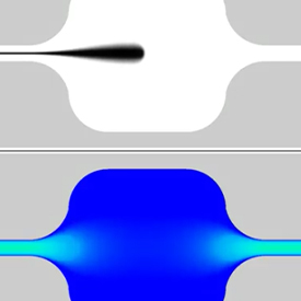
r are the contact angle values between the liquid and the bottom, top, left, and right walls, respectively. A numerical simulation through Coventor software is performed to evaluate the dynamic changes in the filling rate within the microchannel. The simulation results for the blood filling rate in the microchannel are expressed at a specific time stamp, shown in Figure 2. The results portray an increasing instantaneous filling rate of blood in the microchannel following the decrease in contact angle induced by a higher concentration of the nonionic surfactant treated to the microchannel wall.

Figure 2. Numerical simulation of filling rate of capillary driven blood flow under various contact angle conditions at a specific timestamp. (74) Reproduced with permission from ref (74). Copyright 2010 Elsevier.

When in contact with hydrophilic or hydrophobic surfaces, blood forms a meniscus with a contact angle due to surface tension. The Lucas–Washburn (L–W) equation 

(75) is one of the pioneering theoretical definitions for the position of the meniscus over time. In addition, the L–W equation provides the possibility for research to obtain the velocity of the blood formed meniscus through the derivation of the meniscus position. The L–W equation 

(75) can be shown below:

𝐿(𝑡)=𝑅𝜎cos(𝜃)𝑡2𝜇⎯⎯⎯⎯⎯⎯⎯⎯⎯⎯⎯⎯⎯⎯⎯⎯⎯⎯√�(�)=��⁡cos(�)�2�

(10)Here L(t) represents the distance of the liquid driven by the capillary forces. However, the generalized L–W equation solely assumes the constant physical properties from a Newtonian fluid rather than considering the non-Newtonian fluid behavior of blood. Cito et al. 

(76) constructed an enhanced version of the L–W equation incorporating the power law to consider the RBC aggregation and the FL effect. The non-Newtonian fluid apparent viscosity under the Power Law model is defined as

𝜇=𝑘·(𝛾˙)𝑛−1�=�·(�˙)�−1

(11)where γ̇ is the strain rate tensor defined as 

𝛾˙=12𝛾˙𝑖𝑗𝛾˙𝑗𝑖⎯⎯⎯⎯⎯⎯⎯⎯⎯⎯⎯√�˙=12�˙���˙��. The stress tensor term τ is computed as τ = μγ̇

ij. The updated L–W equation by Cito 

(76) is expressed as

𝐿(𝑡)=𝑅[(𝑛+13𝑛+1)(𝜎cos(𝜃)𝑅𝑘)1/𝑛𝑡]𝑛/𝑛+1�(�)=�[(�+13�+1)(�⁡cos(�)��)1/��]�/�+1

(12)where k is the flow consistency index and n is the power law index, respectively. The power law index, from the Power Law model, characterizes the extent of the non-Newtonian behavior of blood. Both the consistency and power law index rely on blood properties such as hematocrit, the appearance of the FL effect, the formation of RBC aggregates, etc. The updated L–W equation computes the location and velocity of blood flow caused by capillary forces at specified time points within the LOC devices, taking into account the effects of blood flow characteristics such as RBC aggregation and the FL effect on dynamic blood viscosity.Apart from the blood flow behaviors triggered by inherent blood properties, unique flow conditions driven by capillary forces that are portrayed under different microchannel geometries also hold crucial implications for CD blood delivery. Berthier et al. 

(77) studied the spontaneous Concus–Finn condition, the condition to initiate the spontaneous capillary flow within a V-groove microchannel, as shown in Figure 3(a) both experimentally and numerically. Through experimental studies, the spontaneous Concus–Finn filament development of capillary driven blood flow is observed, as shown in Figure 3(b), while the dynamic development of blood flow is numerically simulated through CFD simulation.

Figure 3. (a) Sketch of the cross-section of Berthier’s V-groove microchannel, (b) experimental view of blood in the V-groove microchannel, (78) (c) illustration of the dynamic change of the extension of filament from FLOW 3D under capillary flow at three increasing time intervals. (78) Reproduced with permission from ref (78). Copyright 2014 Elsevier.

Berthier et al. 

(77) characterized the contact angle needed for the initiation of the capillary driving force at a zero-inlet pressure, through the half-angle (α) of the V-groove geometry layout, and its relation to the Concus–Finn filament as shown below:

𝜃<𝜋2−𝛼sin𝛼1+2(ℎ2/𝑤)sin𝛼<cos𝜃{�<�2−�sin⁡�1+2(ℎ2/�)⁡sin⁡�<cos⁡�

(13)Three possible regimes were concluded based on the contact angle value for the initiation of flow and development of Concus–Finn filament:

𝜃>𝜃1𝜃1>𝜃>𝜃0𝜃0no SCFSCF without a Concus−Finn filamentSCF without a Concus−Finn filament{�>�1no SCF�1>�>�0SCF without a Concus−Finn filament�0SCF without a Concus−Finn filament

(14)Under Newton’s Law, the force balance with low Reynolds and Capillary numbers results in the neglect of inertial terms. The force balance between the capillary forces and the viscous force induced by the channel wall is proposed to derive the analytical fluid velocity. This relation between the two forces offers insights into the average flow velocity and the penetration distance function dependent on time. The apparent blood viscosity is defined by Berthier et al. 

(78) through Casson’s law, 

(23) given in eq 1. The research used the FLOW-3D program from Flow Science Inc. software, which solves transient, free-surface problems using the FDM in multiple dimensions. The Volume of Fluid (VOF) method 

(79) is utilized to locate and track the dynamic extension of filament throughout the advancing interface within the channel ahead of the main flow at three progressing time stamps, as depicted in Figure 3(c).

4. Electro-osmotic Flow (EOF) in LOC Systems

ARTICLE SECTIONS

Jump To


The utilization of external forces, such as electric fields, has significantly broadened the possibility of manipulating microfluidic flow in LOC systems. 

(80) Externally applied electric field forces induce a fluid flow from the movement of ions in fluid terms as the “electro-osmotic flow” (EOF).Unique transport phenomena, such as enhanced flow velocity and flow instability, induced by non-Newtonian fluids, particularly viscoelastic fluids, under EOF, have sparked considerable interest in microfluidic devices with simple or complicated geometries within channels. 

(81) However, compared to the study of Newtonian fluids and even other electro-osmotic viscoelastic fluid flows, the literature focusing on the theoretical and numerical modeling of electro-osmotic blood flow is limited due to the complexity of blood properties. Consequently, to obtain a more comprehensive understanding of the complex blood flow behavior under EOF, theoretical and numerical studies of the transport phenomena in the EOF section will be based on the studies of different viscoelastic fluids under EOF rather than that of blood specifically. Despite this limitation, we believe these studies offer valuable insights that can help understand the complex behavior of blood flow under EOF.

4.1. EOF Phenomena

Electro-osmotic flow occurs at the interface between the microchannel wall and bulk phase solution. When in contact with the bulk phase, solution ions are absorbed or dissociated at the solid–liquid interface, resulting in the formation of a charge layer, as shown in Figure 4. This charged channel surface wall interacts with both negative and positive ions in the bulk sample, causing repulsion and attraction forces to create a thin layer of immobilized counterions, known as the Stern layer. The induced electric potential from the wall gradually decreases with an increase in the distance from the wall. The Stern layer potential, commonly termed the zeta potential, controls the intensity of the electrostatic interactions between mobile counterions and, consequently, the drag force from the applied electric field. Next to the Stern layer is the diffuse mobile layer, mainly composed of a mobile counterion. These two layers constitute the “electrical double layer” (EDL), the thickness of which is directly proportional to the ionic strength (concentration) of the bulk fluid. The relationship between the two parameters is characterized by a Debye length (λ

D), expressed as

𝜆𝐷=𝜖𝑘B𝑇2(𝑍𝑒)2𝑐0⎯⎯⎯⎯⎯⎯⎯⎯⎯⎯⎯⎯⎯⎯⎯⎯√��=��B�2(��)2�0

(15)where ϵ is the permittivity of the electrolyte solution, k

B is the Boltzmann constant, T is the electron temperature, Z is the integer valence number, e is the elementary charge, and c

0 is the ionic density.

Figure 4. Schematic diagram of an electro-osmotic flow in a microchannel with negative surface charge. (82) Reproduced with permission from ref (82). Copyright 2012 Woodhead Publishing.

When an electric field is applied perpendicular to the EDL, viscous drag is generated due to the movement of excess ions in the EDL. Electro-osmotic forces can be attributed to the externally applied electric potential (ϕ) and the zeta potential, the system wall induced potential by charged walls (ψ). As illustrated in Figure 4, the majority of ions in the bulk phase have a uniform velocity profile, except for a shear rate condition confined within an extremely thin Stern layer. Therefore, EOF displays a unique characteristic of a “near flat” or plug flow velocity profile, different from the parabolic flow typically induced by pressure-driven microfluidic flow (Hagen–Poiseuille flow). The plug-shaped velocity profile of the EOF possesses a high shear rate above the Stern layer.Overall, the EOF velocity magnitude is typically proportional to the Debye Length (λ

D), zeta potential, and magnitude of the externally applied electric field, while a more viscous liquid reduces the EOF velocity.

4.2. Modeling on Electro-osmotic Viscoelastic Fluid Flow

4.2.1. Theoretical Basis of EOF Mechanisms

The EOF of an incompressible viscoelastic fluid is commonly governed by the continuity and incompressible N–S equations, as shown in eqs 7 and 8, where the stress tensor and the electrostatic force term are coupled. The electro-osmotic body force term F, representing the body force exerted by the externally applied electric force, is defined as 

𝐹⇀=𝑝𝐸𝐸⇀�⇀=���⇀, where ρ

E and 

𝐸⇀�⇀ are the net electric charge density and the applied external electric field, respectively.Numerous models are established to theoretically study the externally applied electric potential and the system wall induced potential by charged walls. The following Laplace equation, expressed as eq 16, is generally adapted and solved to calculate the externally applied potential (ϕ).

∇2𝜙=0∇2�=0

(16)Ion diffusion under applied electric fields, together with mass transport resulting from convection and diffusion, transports ionic solutions in bulk flow under electrokinetic processes. The Nernst–Planck equation can describe these transport methods, including convection, diffusion, and electro-diffusion. Therefore, the Nernst–Planck equation is used to determine the distribution of the ions within the electrolyte. The electric potential induced by the charged channel walls follows the Poisson–Nernst–Plank (PNP) equation, which can be written as eq 17.

∇·[𝐷𝑖∇𝑛𝑖−𝑢⇀𝑛𝑖+𝑛𝑖𝐷𝑖𝑧𝑖𝑒𝑘𝑏𝑇∇(𝜙+𝜓)]=0∇·[��∇��−�⇀��+����������∇(�+�)]=0

(17)where D

in

i, and z

i are the diffusion coefficient, ionic concentration, and ionic valence of the ionic species I, respectively. However, due to the high nonlinearity and numerical stiffness introduced by different lengths and time scales from the PNP equations, the Poisson–Boltzmann (PB) model is often considered the major simplified method of the PNP equation to characterize the potential distribution of the EDL region in microchannels. In the PB model, it is assumed that the ionic species in the fluid follow the Boltzmann distribution. This model is typically valid for steady-state problems where charge transport can be considered negligible, the EDLs do not overlap with each other, and the intrinsic potentials are low. It provides a simplified representation of the potential distribution in the EDL region. The PB equation governing the EDL electric potential distribution is described as

∇2𝜓=(2𝑒𝑧𝑛0𝜀𝜀0)sinh(𝑧𝑒𝜓𝑘b𝑇)∇2�=(2���0��0)⁡sinh(����b�)

(18)where n

0 is the ion bulk concentration, z is the ionic valence, and ε

0 is the electric permittivity in the vacuum. Under low electric potential conditions, an even further simplified model to illustrate the EOF phenomena is the Debye–Hückel (DH) model. The DH model is derived by obtaining a charge density term by expanding the exponential term of the Boltzmann equation in a Taylor series.

4.2.2. EOF Modeling for Viscoelastic Fluids

Many studies through numerical modeling were performed to obtain a deeper understanding of the effect exhibited by externally applied electric fields on viscoelastic flow in microchannels under various geometrical designs. Bello et al. 

(83) found that methylcellulose solution, a non-Newtonian polymer solution, resulted in stronger electro-osmotic mobility in experiments when compared to the predictions by the Helmholtz–Smoluchowski equation, which is commonly used to define the velocity of EOF of a Newtonian fluid. Being one of the pioneers to identify the discrepancies between the EOF of Newtonian and non-Newtonian fluids, Bello et al. attributed such discrepancies to the presence of a very high shear rate in the EDL, resulting in a change in the orientation of the polymer molecules. Park and Lee 

(84) utilized the FVM to solve the PB equation for the characterization of the electric field induced force. In the study, the concept of fractional calculus for the Oldroyd-B model was adapted to illustrate the elastic and memory effects of viscoelastic fluids in a straight microchannel They observed that fluid elasticity and increased ratio of viscoelastic fluid contribution to overall fluid viscosity had a significant impact on the volumetric flow rate and sensitivity of velocity to electric field strength compared to Newtonian fluids. Afonso et al. 

(85) derived an analytical expression for EOF of viscoelastic fluid between parallel plates using the DH model to account for a zeta potential condition below 25 mV. The study established the understanding of the electro-osmotic viscoelastic fluid flow under low zeta potential conditions. Apart from the electrokinetic forces, pressure forces can also be coupled with EOF to generate a unique fluid flow behavior within the microchannel. Sousa et al. 

(86) analytically studied the flow of a standard viscoelastic solution by combining the pressure gradient force with an externally applied electric force. It was found that, at a near wall skimming layer and the outer layer away from the wall, macromolecules migrating away from surface walls in viscoelastic fluids are observed. In the study, the Phan-Thien Tanner (PTT) constitutive model is utilized to characterize the viscoelastic properties of the solution. The approach is found to be valid when the EDL is much thinner than the skimming layer under an enhanced flow rate. Zhao and Yang 

(87) solved the PB equation and Carreau model for the characterization of the EOF mechanism and non-Newtonian fluid respectively through the FEM. The numerical results depict that, different from the EOF of Newtonian fluids, non-Newtonian fluids led to an increase of electro-osmotic mobility for shear thinning fluids but the opposite for shear thickening fluids.Like other fluid transport driving forces, EOF within unique geometrical layouts also portrays unique transport phenomena. Pimenta and Alves 

(88) utilized the FVM to perform numerical simulations of the EOF of viscoelastic fluids considering the PB equation and the Oldroyd-B model, in a cross-slot and flow-focusing microdevices. It was found that electroelastic instabilities are formed due to the development of large stresses inside the EDL with streamlined curvature at geometry corners. Bezerra et al. 

(89) used the FDM to numerically analyze the vortex formation and flow instability from an electro-osmotic non-Newtonian fluid flow in a microchannel with a nozzle geometry and parallel wall geometry setting. The PNP equation is utilized to characterize the charge motion in the EOF and the PTT model for non-Newtonian flow characterization. A constriction geometry is commonly utilized in blood flow adapted in LOC systems due to the change in blood flow behavior under narrow dimensions in a microchannel. Ji et al. 

(90) recently studied the EOF of viscoelastic fluid in a constriction microchannel connected by two relatively big reservoirs on both ends (as seen in Figure 5) filled with the polyacrylamide polymer solution, a viscoelastic fluid, and an incompressible monovalent binary electrolyte solution KCl.

Figure 5. Schematic diagram of a negatively charged constriction microchannel connected to two reservoirs at both ends. An electro-osmotic flow is induced in the system by the induced potential difference between the anode and cathode. (90) Reproduced with permission from ref (90). Copyright 2021 The Authors, under the terms of the Creative Commons (CC BY 4.0) License https://creativecommons.org/licenses/by/4.0/.

In studying the EOF of viscoelastic fluids, the Oldroyd-B model is often utilized to characterize the polymeric stress tensor and the deformation rate of the fluid. The Oldroyd-B model is expressed as follows:

𝜏=𝜂p𝜆(𝐜−𝐈)�=�p�(�−�)

(19)where η

p, λ, c, and I represent the polymer dynamic viscosity, polymer relaxation time, symmetric conformation tensor of the polymer molecules, and the identity matrix, respectively.A log-conformation tensor approach is taken to prevent convergence difficulty induced by the viscoelastic properties. The conformation tensor (c) in the polymeric stress tensor term is redefined by a new tensor (Θ) based on the natural logarithm of the c. The new tensor is defined as

Θ=ln(𝐜)=𝐑ln(𝚲)𝐑Θ=ln(�)=�⁡ln(�)�

(20)in which Λ is the diagonal matrix and R is the orthogonal matrix.Under the new conformation tensor, the induced EOF of a viscoelastic fluid is governed by the continuity and N–S equations adapting the Oldroyd-B model, which is expressed as

∂𝚯∂𝑡+𝐮·∇𝚯=𝛀Θ−ΘΩ+2𝐁+1𝜆(eΘ−𝐈)∂�∂�+�·∇�=�Θ−ΘΩ+2�+1�(eΘ−�)

(21)where Ω and B represent the anti-symmetric matrix and the symmetric traceless matrix of the decomposition of the velocity gradient tensor ∇u, respectively. The conformation tensor can be recovered by c = exp(Θ). The PB model and Laplace equation are utilized to characterize the charged channel wall induced potential and the externally applied potential.The governing equations are numerically solved through the FVM by RheoTool, 

(42) an open-source viscoelastic EOF solver on the OpenFOAM platform. A SIMPLEC (Semi-Implicit Method for Pressure Linked Equations-Consistent) algorithm was applied to solve the velocity-pressure coupling. The pressure field and velocity field were computed by the PCG (Preconditioned Conjugate Gradient) solver and the PBiCG (Preconditioned Biconjugate Gradient) solver, respectively.Ranging magnitudes of an applied electric field or fluid concentration induce both different streamlines and velocity magnitudes at various locations and times of the microchannel. In the study performed by Ji et al., 

(90) notable fluctuation of streamlines and vortex formation is formed at the upper stream entrance of the constriction as shown in Figure 6(a) and (b), respectively, due to the increase of electrokinetic effect, which is seen as a result of the increase in polymeric stress (τ

xx). 

(90) The contraction geometry enhances the EOF velocity within the constriction channel under high E

app condition (600 V/cm). Such phenomena can be attributed to the dependence of electro-osmotic viscoelastic fluid flow on the system wall surface and bulk fluid properties. 

(91)

Figure 6. Schematic diagram of vortex formation and streamlines of EOF depicting flow instability at (a) 1.71 s and (b) 1.75 s. Spatial distribution of the elastic normal stress at (c) high Eapp condition. Streamline of an electro-osmotic flow under Eapp of 600 V/cm (90) for (d) non-Newtonian and (e) Newtonian fluid through a constriction geometry. Reproduced with permission from ref (90). Copyright 2021 The Authors, under the terms of the Creative Commons (CC BY 4.0) License https://creativecommons.org/licenses/by/4.0/.

As elastic normal stress exceeds the local shear stress, flow instability and vortex formation occur. The induced elastic stress under EOF not only enhances the instability of the flow but often generates an irregular secondary flow leading to strong disturbance. 

(92) It is also vital to consider the effect of the constriction layout of microchannels on the alteration of the field strength within the system. The contraction geometry enhances a larger electric field strength compared with other locations of the channel outside the constriction region, resulting in a higher velocity gradient and stronger extension on the polymer within the viscoelastic solution. Following the high shear flow condition, a higher magnitude of stretch for polymer molecules in viscoelastic fluids exhibits larger elastic stresses and enhancement of vortex formation at the region. 

(93)As shown in Figure 6(c), significant elastic normal stress occurs at the inlet of the constriction microchannel. Such occurrence of a polymeric flow can be attributed to the dominating elongational flow, giving rise to high deformation of the polymers within the viscoelastic fluid flow, resulting in higher elastic stress from the polymers. Such phenomena at the entrance result in the difference in velocity streamline as circled in Figure 6(d) compared to that of the Newtonian fluid at the constriction entrance in Figure 6(e). 

(90) The difference between the Newtonian and polymer solution at the exit, as circled in Figure 6(d) and (e), can be attributed to the extrudate swell effect of polymers 

(94) within the viscoelastic fluid flow. The extrudate swell effect illustrates that, as polymers emerge from the constriction exit, they tend to contract in the flow direction and grow in the normal direction, resulting in an extrudate diameter greater than the channel size. The deformation of polymers within the polymeric flow at both the entrance and exit of the contraction channel facilitates the change in shear stress conditions of the flow, leading to the alteration in streamlines of flows for each region.

4.3. EOF Applications in LOC Systems

4.3.1. Mixing in LOC Systems

Rather than relying on the micromixing controlled by molecular diffusion under low Reynolds number conditions, active mixers actively leverage convective instability and vortex formation induced by electro-osmotic flows from alternating current (AC) or direct current (DC) electric fields. Such adaptation is recognized as significant breakthroughs for promotion of fluid mixing in chemical and biological applications such as drug delivery, medical diagnostics, chemical synthesis, and so on. 

(95)Many researchers proposed novel designs of electro-osmosis micromixers coupled with numerical simulations in conjunction with experimental findings to increase their understanding of the role of flow instability and vortex formation in the mixing process under electrokinetic phenomena. Matsubara and Narumi 

(96) numerically modeled the mixing process in a microchannel with four electrodes on each side of the microchannel wall, which generated a disruption through unstable electro-osmotic vortices. It was found that particle mixing was sensitive to both the convection effect induced by the main and secondary vortex within the micromixer and the change in oscillation frequency caused by the supplied AC voltage when the Reynolds number was varied. Qaderi et al. 

(97) adapted the PNP equation to numerically study the effect of the geometry and zeta potential configuration of the microchannel on the mixing process with a combined electro-osmotic pressure driven flow. It was reported that the application of heterogeneous zeta potential configuration enhances the mixing efficiency by around 23% while the height of the hurdles increases the mixing efficiency at most 48.1%. Cho et al. 

(98) utilized the PB model and Laplace equation to numerically simulate the electro-osmotic non-Newtonian fluid mixing process within a wavy and block layout of microchannel walls. The Power Law model is adapted to describe the fluid rheological characteristic. It was found that shear-thinning fluids possess a higher volumetric flow rate, which could result in poorer mixing efficiency compared to that of Newtonian fluids. Numerous studies have revealed that flow instability and vortex generation, in particular secondary vortices produced by barriers or greater magnitudes of heterogeneous zeta potential distribution, enhance mixing by increasing bulk flow velocity and reducing flow distance.To better understand the mechanism of disturbance formed in the system due to externally applied forces, known as electrokinetic instability, literature often utilize the Rayleigh (Ra) number, 

(1) as described below:

𝑅𝑎𝑣=𝑢ev𝑢eo=(𝛾−1𝛾+1)2𝑊𝛿2𝐸el2𝐻2𝜁𝛿Ra�=�ev�eo=(�−1�+1)2��2�el2�2��

(22)where γ is the conductivity ratio of the two streams and can be written as 

𝛾=𝜎el,H𝜎el,L�=�el,H�el,L. The Ra number characterizes the ratio between electroviscous and electro-osmotic flow. A high Ra

v value often results in good mixing. It is evident that fluid properties such as the conductivity (σ) of the two streams play a key role in the formation of disturbances to enhance mixing in microsystems. At the same time, electrokinetic parameters like the zeta potential (ζ) in the Ra number is critical in the characterization of electro-osmotic velocity and a slip boundary condition at the microchannel wall.To understand the mixing result along the channel, the concentration field can be defined and simulated under the assumption of steady state conditions and constant diffusion coefficient for each of the working fluid within the system through the convection–diffusion equation as below:

∂𝑐𝒊∂𝑡+∇⇀(𝑐𝑖𝑢⇀−𝐷𝑖∇⇀𝑐𝒊)=0∂��∂�+∇⇀(���⇀−��∇⇀��)=0

(23)where c

i is the species concentration of species i and D

i is the diffusion coefficient of the corresponding species.The standard deviation of concentration (σ

sd) can be adapted to evaluate the mixing quality of the system. 

(97) The standard deviation for concentration at a specific portion of the channel may be calculated using the equation below:

𝜎sd=∫10(𝐶∗(𝑦∗)−𝐶m)2d𝑦∗∫10d𝑦∗⎯⎯⎯⎯⎯⎯⎯⎯⎯⎯⎯⎯⎯⎯⎯⎯⎯⎯⎯⎯⎯⎯⎯⎯⎯⎯⎯⎯⎯⎯⎯⎯⎯⎯⎯⎯⎯⎯�sd=∫01(�*(�*)−�m)2d�*∫01d�*

(24)where C*(y*) and C

m are the non-dimensional concentration profile and the mean concentration at the portion, respectively. C* is the non-dimensional concentration and can be calculated as 

𝐶∗=𝐶𝐶ref�*=��ref, where C

ref is the reference concentration defined as the bulk solution concentration. The mean concentration profile can be calculated as 

𝐶m=∫10(𝐶∗(𝑦∗)d𝑦∗∫10d𝑦∗�m=∫01(�*(�*)d�*∫01d�*. With the standard deviation of concentration, the mixing efficiency 

(97) can then be calculated as below:

𝜀𝑥=1−𝜎sd𝜎sd,0��=1−�sd�sd,0

(25)where σ

sd,0 is the standard derivation of the case of no mixing. The value of the mixing efficiency is typically utilized in conjunction with the simulated flow field and concentration field to explore the effect of geometrical and electrokinetic parameters on the optimization of the mixing results.

5. Summary

ARTICLE SECTIONS

Jump To


5.1. Conclusion

Viscoelastic fluids such as blood flow in LOC systems are an essential topic to proceed with diagnostic analysis and research through microdevices in the biomedical and pharmaceutical industries. The complex blood flow behavior is tightly controlled by the viscoelastic characteristics of blood such as the dynamic viscosity and the elastic property of RBCs under various shear rate conditions. Furthermore, the flow behaviors under varied driving forces promote an array of microfluidic transport phenomena that are critical to the management of blood flow and other adapted viscoelastic fluids in LOC systems. This review addressed the blood flow phenomena, the complicated interplay between shear rate and blood flow behaviors, and their numerical modeling under LOC systems through the lens of the viscoelasticity characteristic. Furthermore, a theoretical understanding of capillary forces and externally applied electric forces leads to an in-depth investigation of the relationship between blood flow patterns and the key parameters of the two driving forces, the latter of which is introduced through the lens of viscoelastic fluids, coupling numerical modeling to improve the knowledge of blood flow manipulation in LOC systems. The flow disturbances triggered by the EOF of viscoelastic fluids and their impact on blood flow patterns have been deeply investigated due to their important role and applications in LOC devices. Continuous advancements of various numerical modeling methods with experimental findings through more efficient and less computationally heavy methods have served as an encouraging sign of establishing more accurate illustrations of the mechanisms for multiphase blood and other viscoelastic fluid flow transport phenomena driven by various forces. Such progress is fundamental for the manipulation of unique transport phenomena, such as the generated disturbances, to optimize functionalities offered by microdevices in LOC systems.

The following section will provide further insights into the employment of studied blood transport phenomena to improve the functionality of micro devices adapting LOC technology. A discussion of the novel roles that external driving forces play in microfluidic flow behaviors is also provided. Limitations in the computational modeling of blood flow and electrokinetic phenomena in LOC systems will also be emphasized, which may provide valuable insights for future research endeavors. These discussions aim to provide guidance and opportunities for new paths in the ongoing development of LOC devices that adapt blood flow.

5.2. Future Directions

5.2.1. Electro-osmosis Mixing in LOC Systems

Despite substantial research, mixing results through flow instability and vortex formation phenomena induced by electro-osmotic mixing still deviate from the effective mixing results offered by chaotic mixing results such as those seen in turbulent flows. However, recent discoveries of a mixing phenomenon that is generally observed under turbulent flows are found within electro-osmosis micromixers under low Reynolds number conditions. Zhao 

(99) experimentally discovered a rapid mixing process in an AC applied micromixer, where the power spectrum of concentration under an applied voltage of 20 V

p-p induces a −5/3 slope within a frequency range. This value of the slope is considered as the O–C spectrum in macroflows, which is often visible under relatively high Re conditions, such as the Taylor microscale Reynolds number Re > 500 in turbulent flows. 

(100) However, the Re value in the studied system is less than 1 at the specific location and applied voltage. A secondary flow is also suggested to occur close to microchannel walls, being attributed to the increase of convective instability within the system.Despite the experimental phenomenon proposed by Zhao et al., 

(99) the range of effects induced by vital parameters of an EOF mixing system on the enhanced mixing results and mechanisms of disturbance generated by the turbulent-like flow instability is not further characterized. Such a gap in knowledge may hinder the adaptability and commercialization of the discovery of micromixers. One of the parameters for further evaluation is the conductivity gradient of the fluid flow. A relatively strong conductivity gradient (5000:1) was adopted in the system due to the conductive properties of the two fluids. The high conductivity gradients may contribute to the relatively large Rayleigh number and differences in EDL layer thickness, resulting in an unusual disturbance in laminar flow conditions and enhanced mixing results. However, high conductivity gradients are not always achievable by the working fluids due to diverse fluid properties. The reliance on turbulent-like phenomena and rapid mixing results in a large conductivity gradient should be established to prevent the limited application of fluids for the mixing system. In addition, the proposed system utilizes distinct zeta potential distributions at the top and bottom walls due to their difference in material choices, which may be attributed to the flow instability phenomena. Further studies should be made on varying zeta potential magnitude and distribution to evaluate their effect on the slip boundary conditions of the flow and the large shear rate condition close to the channel wall of EOF. Such a study can potentially offer an optimized condition in zeta potential magnitude through material choices and geometrical layout of the zeta potential for better mixing results and manipulation of mixing fluid dynamics. The two vital parameters mentioned above can be varied with the aid of numerical simulation to understand the effect of parameters on the interaction between electro-osmotic forces and electroviscous forces. At the same time, the relationship of developed streamlines of the simulated velocity and concentration field, following their relationship with the mixing results, under the impact of these key parameters can foster more insight into the range of impact that the two parameters have on the proposed phenomena and the microfluidic dynamic principles of disturbances.

In addition, many of the current investigations of electrokinetic mixers commonly emphasize the fluid dynamics of mixing for Newtonian fluids, while the utilization of biofluids, primarily viscoelastic fluids such as blood, and their distinctive response under shear forces in these novel mixing processes of LOC systems are significantly less studied. To develop more compatible microdevice designs and efficient mixing outcomes for the biomedical industry, it is necessary to fill the knowledge gaps in the literature on electro-osmotic mixing for biofluids, where properties of elasticity, dynamic viscosity, and intricate relationship with shear flow from the fluid are further considered.

5.2.2. Electro-osmosis Separation in LOC Systems

Particle separation in LOC devices, particularly in biological research and diagnostics, is another area where disturbances may play a significant role in optimization. 

(101) Plasma analysis in LOC systems under precise control of blood flow phenomena and blood/plasma separation procedures can detect vital information about infectious diseases from particular antibodies and foreign nucleic acids for medical treatments, diagnostics, and research, 

(102) offering more efficient results and simple operating procedures compared to that of the traditional centrifugation method for blood and plasma separation. However, the adaptability of LOC devices for blood and plasma separation is often hindered by microchannel clogging, where flow velocity and plasma yield from LOC devices is reduced due to occasional RBC migration and aggregation at the filtration entrance of microdevices. 

(103)It is important to note that the EOF induces flow instability close to microchannel walls, which may provide further solutions to clogging for the separation process of the LOC systems. Mohammadi et al. 

(104) offered an anti-clogging effect of RBCs at the blood and plasma separating device filtration entry, adjacent to the surface wall, through RBC disaggregation under high shear rate conditions generated by a forward and reverse EOF direction.

Further theoretical and numerical research can be conducted to characterize the effect of high shear rate conditions near microchannel walls toward the detachment of binding blood cells on surfaces and the reversibility of aggregation. Through numerical modeling with varying electrokinetic parameters to induce different degrees of disturbances or shear conditions at channel walls, it may be possible to optimize and better understand the process of disrupting the forces that bind cells to surface walls and aggregated cells at filtration pores. RBCs that migrate close to microchannel walls are often attracted by the adhesion force between the RBC and the solid surface originating from the van der Waals forces. Following RBC migration and attachment by adhesive forces adjacent to the microchannel walls as shown in Figure 7, the increase in viscosity at the region causes a lower shear condition and encourages RBC aggregation (cell–cell interaction), which clogs filtering pores or microchannels and reduces flow velocity at filtration region. Both the impact that shear forces and disturbances may induce on cell binding forces with surface walls and other cells leading to aggregation may suggest further characterization. Kinetic parameters such as activation energy and the rate-determining step for cell binding composition attachment and detachment should be considered for modeling the dynamics of RBCs and blood flows under external forces in LOC separation devices.

Figure 7. Schematic representations of clogging at a microchannel pore following the sequence of RBC migration, cell attachment to channel walls, and aggregation. (105) Reproduced with permission from ref (105). Copyright 2018 The Authors under the terms of the Creative Commons (CC BY 4.0) License https://creativecommons.org/licenses/by/4.0/.

5.2.3. Relationship between External Forces and Microfluidic Systems

In blood flow, a thicker CFL suggests a lower blood viscosity, suggesting a complex relationship between shear stress and shear rate, affecting the blood viscosity and blood flow. Despite some experimental and numerical studies on electro-osmotic non-Newtonian fluid flow, limited literature has performed an in-depth investigation of the role that applied electric forces and other external forces could play in the process of CFL formation. Additional studies on how shear rates from external forces affect CFL formation and microfluidic flow dynamics can shed light on the mechanism of the contribution induced by external driving forces to the development of a separate phase of layer, similar to CFL, close to the microchannel walls and distinct from the surrounding fluid within the system, then influencing microfluidic flow dynamics.One of the mechanisms of phenomena to be explored is the formation of the Exclusion Zone (EZ) region following a “Self-Induced Flow” (SIF) phenomenon discovered by Li and Pollack, 

(106) as shown in Figure 8(a) and (b), respectively. A spontaneous sustained axial flow is observed when hydrophilic materials are immersed in water, resulting in the buildup of a negative layer of charges, defined as the EZ, after water molecules absorb infrared radiation (IR) energy and break down into H and OH

+.

Figure 8. Schematic representations of (a) the Exclusion Zone region and (b) the Self Induced Flow through visualization of microsphere movement within a microchannel. (106) Reproduced with permission from ref (106). Copyright 2020 The Authors under the terms of the Creative Commons (CC BY 4.0) License https://creativecommons.org/licenses/by/4.0/.

Despite the finding of such a phenomenon, the specific mechanism and role of IR energy have yet to be defined for the process of EZ development. To further develop an understanding of the role of IR energy in such phenomena, a feasible study may be seen through the lens of the relationships between external forces and microfluidic flow. In the phenomena, the increase of SIF velocity under a rise of IR radiation resonant characteristics is shown in the participation of the external electric field near the microchannel walls under electro-osmotic viscoelastic fluid flow systems. The buildup of negative charges at the hydrophilic surfaces in EZ is analogous to the mechanism of electrical double layer formation. Indeed, research has initiated the exploration of the core mechanisms for EZ formation through the lens of the electrokinetic phenomena. 

(107) Such a similarity of the role of IR energy and the transport phenomena of SIF with electrokinetic phenomena paves the way for the definition of the unknown SIF phenomena and EZ formation. Furthermore, Li and Pollack 

(106) suggest whether CFL formation might contribute to a SIF of blood using solely IR radiation, a commonly available source of energy in nature, as an external driving force. The proposition may be proven feasible with the presence of the CFL region next to the negatively charged hydrophilic endothelial glycocalyx layer, coating the luminal side of blood vessels. 

(108) Further research can dive into the resonating characteristics between the formation of the CFL region next to the hydrophilic endothelial glycocalyx layer and that of the EZ formation close to hydrophilic microchannel walls. Indeed, an increase in IR energy is known to rapidly accelerate EZ formation and SIF velocity, depicting similarity to the increase in the magnitude of electric field forces and greater shear rates at microchannel walls affecting CFL formation and EOF velocity. Such correlation depicts a future direction in whether SIF blood flow can be observed and characterized theoretically further through the lens of the relationship between blood flow and shear forces exhibited by external energy.

The intricate link between the CFL and external forces, more specifically the externally applied electric field, can receive further attention to provide a more complete framework for the mechanisms between IR radiation and EZ formation. Such characterization may also contribute to a greater comprehension of the role IR can play in CFL formation next to the endothelial glycocalyx layer as well as its role as a driving force to propel blood flow, similar to the SIF, but without the commonly assumed pressure force from heart contraction as a source of driving force.

5.3. Challenges

Although there have been significant improvements in blood flow modeling under LOC systems over the past decade, there are still notable constraints that may require special attention for numerical simulation applications to benefit the adaptability of the designs and functionalities of LOC devices. Several points that require special attention are mentioned below:

1.The majority of CFD models operate under the relationship between the viscoelasticity of blood and the shear rate conditions of flow. The relative effect exhibited by the presence of highly populated RBCs in whole blood and their forces amongst the cells themselves under complex flows often remains unclearly defined. Furthermore, the full range of cell populations in whole blood requires a much more computational load for numerical modeling. Therefore, a vital goal for future research is to evaluate a reduced modeling method where the impact of cell–cell interaction on the viscoelastic property of blood is considered.
2.Current computational methods on hemodynamics rely on continuum models based upon non-Newtonian rheology at the macroscale rather than at molecular and cellular levels. Careful considerations should be made for the development of a constructive framework for the physical and temporal scales of micro/nanoscale systems to evaluate the intricate relationship between fluid driving forces, dynamic viscosity, and elasticity.
3.Viscoelastic fluids under the impact of externally applied electric forces often deviate from the assumptions of no-slip boundary conditions due to the unique flow conditions induced by externally applied forces. Furthermore, the mechanism of vortex formation and viscoelastic flow instability at laminar flow conditions should be better defined through the lens of the microfluidic flow phenomenon to optimize the prediction of viscoelastic flow across different geometrical layouts. Mathematical models and numerical methods are needed to better predict such disturbance caused by external forces and the viscoelasticity of fluids at such a small scale.
4.Under practical situations, zeta potential distribution at channel walls frequently deviates from the common assumption of a constant distribution because of manufacturing faults or inherent surface charges prior to the introduction of electrokinetic influence. These discrepancies frequently lead to inconsistent surface potential distribution, such as excess positive ions at relatively more negatively charged walls. Accordingly, unpredicted vortex formation and flow instability may occur. Therefore, careful consideration should be given to these discrepancies and how they could trigger the transport process and unexpected results of a microdevice.

Author Information

ARTICLE SECTIONS

Jump To


  • Corresponding Authors
    • Zhe Chen – Department of Chemical Engineering, School of Chemistry and Chemical Engineering, State Key Laboratory of Metal Matrix Composites, Shanghai Jiao Tong University, Shanghai 200240, P. R. China;  Email: zaccooky@sjtu.edu.cn

    • Bo Ouyang – Department of Chemical Engineering, School of Chemistry and Chemical Engineering, State Key Laboratory of Metal Matrix Composites, Shanghai Jiao Tong University, Shanghai 200240, P. R. China;  Email: bouy93@sjtu.edu.cn
    • Zheng-Hong Luo – Department of Chemical Engineering, School of Chemistry and Chemical Engineering, State Key Laboratory of Metal Matrix Composites, Shanghai Jiao Tong University, Shanghai 200240, P. R. China;  Orcidhttps://orcid.org/0000-0001-9011-6020; Email: luozh@sjtu.edu.cn
  • Authors
    • Bin-Jie Lai – Department of Chemical Engineering, School of Chemistry and Chemical Engineering, State Key Laboratory of Metal Matrix Composites, Shanghai Jiao Tong University, Shanghai 200240, P. R. China;  Orcidhttps://orcid.org/0009-0002-8133-5381
    • Li-Tao Zhu – Department of Chemical Engineering, School of Chemistry and Chemical Engineering, State Key Laboratory of Metal Matrix Composites, Shanghai Jiao Tong University, Shanghai 200240, P. R. China;  Orcidhttps://orcid.org/0000-0001-6514-8864
  • NotesThe authors declare no competing financial interest.

Acknowledgments

ARTICLE SECTIONS

Jump To


This work was supported by the National Natural Science Foundation of China (No. 22238005) and the Postdoctoral Research Foundation of China (No. GZC20231576).

Vocabulary

ARTICLE SECTIONS

Jump To


Microfluidicsthe field of technological and scientific study that investigates fluid flow in channels with dimensions between 1 and 1000 μm
Lab-on-a-Chip Technologythe field of research and technological development aimed at integrating the micro/nanofluidic characteristics to conduct laboratory processes on handheld devices
Computational Fluid Dynamics (CFD)the method utilizing computational abilities to predict physical fluid flow behaviors mathematically through solving the governing equations of corresponding fluid flows
Shear Ratethe rate of change in velocity where one layer of fluid moves past the adjacent layer
Viscoelasticitythe property holding both elasticity and viscosity characteristics relying on the magnitude of applied shear stress and time-dependent strain
Electro-osmosisthe flow of fluid under an applied electric field when charged solid surface is in contact with the bulk fluid
Vortexthe rotating motion of a fluid revolving an axis line

References

ARTICLE SECTIONS

Jump To


This article references 108 other publications.

  1. 1Neethirajan, S.; Kobayashi, I.; Nakajima, M.; Wu, D.; Nandagopal, S.; Lin, F. Microfluidics for food, agriculture and biosystems industries. Lab Chip 201111 (9), 1574– 1586,  DOI: 10.1039/c0lc00230eViewGoogle Scholar
  2. 2Whitesides, G. M. The origins and the future of microfluidics. Nature 2006442 (7101), 368– 373,  DOI: 10.1038/nature05058ViewGoogle Scholar
  3. 3Burklund, A.; Tadimety, A.; Nie, Y.; Hao, N.; Zhang, J. X. J. Chapter One – Advances in diagnostic microfluidics; Elsevier, 2020; DOI:  DOI: 10.1016/bs.acc.2019.08.001 .ViewGoogle Scholar
  4. 4Abdulbari, H. A. Chapter 12 – Lab-on-a-chip for analysis of blood. In Nanotechnology for Hematology, Blood Transfusion, and Artificial Blood; Denizli, A., Nguyen, T. A., Rajan, M., Alam, M. F., Rahman, K., Eds.; Elsevier, 2022; pp 265– 283.ViewGoogle Scholar
  5. 5Vladisavljević, G. T.; Khalid, N.; Neves, M. A.; Kuroiwa, T.; Nakajima, M.; Uemura, K.; Ichikawa, S.; Kobayashi, I. Industrial lab-on-a-chip: Design, applications and scale-up for drug discovery and delivery. Advanced Drug Delivery Reviews 201365 (11), 1626– 1663,  DOI: 10.1016/j.addr.2013.07.017ViewGoogle Scholar
  6. 6Kersaudy-Kerhoas, M.; Dhariwal, R.; Desmulliez, M. P. Y.; Jouvet, L. Hydrodynamic blood plasma separation in microfluidic channels. Microfluid. Nanofluid. 20108 (1), 105– 114,  DOI: 10.1007/s10404-009-0450-5ViewGoogle Scholar
  7. 7Popel, A. S.; Johnson, P. C. Microcirculation and Hemorheology. Annu. Rev. Fluid Mech. 200537 (1), 43– 69,  DOI: 10.1146/annurev.fluid.37.042604.133933ViewGoogle Scholar
  8. 8Fedosov, D. A.; Peltomäki, M.; Gompper, G. Deformation and dynamics of red blood cells in flow through cylindrical microchannels. Soft Matter 201410 (24), 4258– 4267,  DOI: 10.1039/C4SM00248BViewGoogle Scholar
  9. 9Chakraborty, S. Dynamics of capillary flow of blood into a microfluidic channel. Lab Chip 20055 (4), 421– 430,  DOI: 10.1039/b414566fViewGoogle Scholar
  10. 10Tomaiuolo, G.; Guido, S. Start-up shape dynamics of red blood cells in microcapillary flow. Microvascular Research 201182 (1), 35– 41,  DOI: 10.1016/j.mvr.2011.03.004ViewGoogle Scholar
  11. 11Sherwood, J. M.; Dusting, J.; Kaliviotis, E.; Balabani, S. The effect of red blood cell aggregation on velocity and cell-depleted layer characteristics of blood in a bifurcating microchannel. Biomicrofluidics 20126 (2), 24119,  DOI: 10.1063/1.4717755ViewGoogle Scholar
  12. 12Nader, E.; Skinner, S.; Romana, M.; Fort, R.; Lemonne, N.; Guillot, N.; Gauthier, A.; Antoine-Jonville, S.; Renoux, C.; Hardy-Dessources, M.-D. Blood Rheology: Key Parameters, Impact on Blood Flow, Role in Sickle Cell Disease and Effects of Exercise. Frontiers in Physiology 201910, 01329,  DOI: 10.3389/fphys.2019.01329ViewGoogle Scholar
  13. 13Trejo-Soto, C.; Lázaro, G. R.; Pagonabarraga, I.; Hernández-Machado, A. Microfluidics Approach to the Mechanical Properties of Red Blood Cell Membrane and Their Effect on Blood Rheology. Membranes 202212 (2), 217,  DOI: 10.3390/membranes12020217ViewGoogle Scholar
  14. 14Wagner, C.; Steffen, P.; Svetina, S. Aggregation of red blood cells: From rouleaux to clot formation. Comptes Rendus Physique 201314 (6), 459– 469,  DOI: 10.1016/j.crhy.2013.04.004ViewGoogle Scholar
  15. 15Kim, H.; Zhbanov, A.; Yang, S. Microfluidic Systems for Blood and Blood Cell Characterization. Biosensors 202313 (1), 13,  DOI: 10.3390/bios13010013ViewGoogle Scholar
  16. 16Fåhræus, R.; Lindqvist, T. THE VISCOSITY OF THE BLOOD IN NARROW CAPILLARY TUBES. American Journal of Physiology-Legacy Content 193196 (3), 562– 568,  DOI: 10.1152/ajplegacy.1931.96.3.562ViewGoogle Scholar
  17. 17Ascolese, M.; Farina, A.; Fasano, A. The Fåhræus-Lindqvist effect in small blood vessels: how does it help the heart?. J. Biol. Phys. 201945 (4), 379– 394,  DOI: 10.1007/s10867-019-09534-4ViewGoogle Scholar
  18. 18Bento, D.; Fernandes, C. S.; Miranda, J. M.; Lima, R. In vitro blood flow visualizations and cell-free layer (CFL) measurements in a microchannel network. Experimental Thermal and Fluid Science 2019109, 109847,  DOI: 10.1016/j.expthermflusci.2019.109847ViewGoogle Scholar
  19. 19Namgung, B.; Ong, P. K.; Wong, Y. H.; Lim, D.; Chun, K. J.; Kim, S. A comparative study of histogram-based thresholding methods for the determination of cell-free layer width in small blood vessels. Physiological Measurement 201031 (9), N61,  DOI: 10.1088/0967-3334/31/9/N01ViewGoogle Scholar
  20. 20Hymel, S. J.; Lan, H.; Fujioka, H.; Khismatullin, D. B. Cell trapping in Y-junction microchannels: A numerical study of the bifurcation angle effect in inertial microfluidics. Phys. Fluids (1994) 201931 (8), 082003,  DOI: 10.1063/1.5113516ViewGoogle Scholar
  21. 21Li, X.; Popel, A. S.; Karniadakis, G. E. Blood-plasma separation in Y-shaped bifurcating microfluidic channels: a dissipative particle dynamics simulation study. Phys. Biol. 20129 (2), 026010,  DOI: 10.1088/1478-3975/9/2/026010ViewGoogle Scholar
  22. 22Yin, X.; Thomas, T.; Zhang, J. Multiple red blood cell flows through microvascular bifurcations: Cell free layer, cell trajectory, and hematocrit separation. Microvascular Research 201389, 47– 56,  DOI: 10.1016/j.mvr.2013.05.002ViewGoogle Scholar
  23. 23Shibeshi, S. S.; Collins, W. E. The Rheology of Blood Flow in a Branched Arterial System. Appl. Rheol 200515 (6), 398– 405,  DOI: 10.1515/arh-2005-0020ViewGoogle Scholar
  24. 24Sequeira, A.; Janela, J. An Overview of Some Mathematical Models of Blood Rheology. In A Portrait of State-of-the-Art Research at the Technical University of Lisbon; Pereira, M. S., Ed.; Springer Netherlands: Dordrecht, 2007; pp 65– 87.ViewGoogle Scholar
  25. 25Walburn, F. J.; Schneck, D. J. A constitutive equation for whole human blood. Biorheology 197613, 201– 210,  DOI: 10.3233/BIR-1976-13307ViewGoogle Scholar
  26. 26Quemada, D. A rheological model for studying the hematocrit dependence of red cell-red cell and red cell-protein interactions in blood. Biorheology 198118, 501– 516,  DOI: 10.3233/BIR-1981-183-615ViewGoogle Scholar
  27. 27Varchanis, S.; Dimakopoulos, Y.; Wagner, C.; Tsamopoulos, J. How viscoelastic is human blood plasma?. Soft Matter 201814 (21), 4238– 4251,  DOI: 10.1039/C8SM00061AViewGoogle Scholar
  28. 28Apostolidis, A. J.; Moyer, A. P.; Beris, A. N. Non-Newtonian effects in simulations of coronary arterial blood flow. J. Non-Newtonian Fluid Mech. 2016233, 155– 165,  DOI: 10.1016/j.jnnfm.2016.03.008ViewGoogle Scholar
  29. 29Luo, X. Y.; Kuang, Z. B. A study on the constitutive equation of blood. J. Biomech. 199225 (8), 929– 934,  DOI: 10.1016/0021-9290(92)90233-QViewGoogle Scholar
  30. 30Oldroyd, J. G.; Wilson, A. H. On the formulation of rheological equations of state. Proceedings of the Royal Society of London. Series A. Mathematical and Physical Sciences 1950200 (1063), 523– 541,  DOI: 10.1098/rspa.1950.0035ViewGoogle Scholar
  31. 31Prado, G.; Farutin, A.; Misbah, C.; Bureau, L. Viscoelastic transient of confined red blood cells. Biophys J. 2015108 (9), 2126– 2136,  DOI: 10.1016/j.bpj.2015.03.046ViewGoogle Scholar
  32. 32Huang, C. R.; Pan, W. D.; Chen, H. Q.; Copley, A. L. Thixotropic properties of whole blood from healthy human subjects. Biorheology 198724 (6), 795– 801,  DOI: 10.3233/BIR-1987-24630ViewGoogle Scholar
  33. 33Anand, M.; Kwack, J.; Masud, A. A new generalized Oldroyd-B model for blood flow in complex geometries. International Journal of Engineering Science 201372, 78– 88,  DOI: 10.1016/j.ijengsci.2013.06.009ViewGoogle Scholar
  34. 34Horner, J. S.; Armstrong, M. J.; Wagner, N. J.; Beris, A. N. Investigation of blood rheology under steady and unidirectional large amplitude oscillatory shear. J. Rheol. 201862 (2), 577– 591,  DOI: 10.1122/1.5017623ViewGoogle Scholar
  35. 35Horner, J. S.; Armstrong, M. J.; Wagner, N. J.; Beris, A. N. Measurements of human blood viscoelasticity and thixotropy under steady and transient shear and constitutive modeling thereof. J. Rheol. 201963 (5), 799– 813,  DOI: 10.1122/1.5108737ViewGoogle Scholar
  36. 36Armstrong, M.; Tussing, J. A methodology for adding thixotropy to Oldroyd-8 family of viscoelastic models for characterization of human blood. Phys. Fluids 202032 (9), 094111,  DOI: 10.1063/5.0022501ViewGoogle Scholar
  37. 37Crank, J.; Nicolson, P. A practical method for numerical evaluation of solutions of partial differential equations of the heat-conduction type. Mathematical Proceedings of the Cambridge Philosophical Society 194743 (1), 50– 67,  DOI: 10.1017/S0305004100023197ViewGoogle Scholar
  38. 38Clough, R. W. Original formulation of the finite element method. Finite Elements in Analysis and Design 19907 (2), 89– 101,  DOI: 10.1016/0168-874X(90)90001-UViewGoogle Scholar
  39. 39Liu, W. K.; Liu, Y.; Farrell, D.; Zhang, L.; Wang, X. S.; Fukui, Y.; Patankar, N.; Zhang, Y.; Bajaj, C.; Lee, J.Immersed finite element method and its applications to biological systems. Computer Methods in Applied Mechanics and Engineering 2006195 (13), 1722– 1749,  DOI: 10.1016/j.cma.2005.05.049ViewGoogle Scholar
  40. 40Lopes, D.; Agujetas, R.; Puga, H.; Teixeira, J.; Lima, R.; Alejo, J. P.; Ferrera, C. Analysis of finite element and finite volume methods for fluid-structure interaction simulation of blood flow in a real stenosed artery. International Journal of Mechanical Sciences 2021207, 106650,  DOI: 10.1016/j.ijmecsci.2021.106650ViewGoogle Scholar
  41. 41Favero, J. L.; Secchi, A. R.; Cardozo, N. S. M.; Jasak, H. Viscoelastic flow analysis using the software OpenFOAM and differential constitutive equations. J. Non-Newtonian Fluid Mech. 2010165 (23), 1625– 1636,  DOI: 10.1016/j.jnnfm.2010.08.010ViewGoogle Scholar
  42. 42Pimenta, F.; Alves, M. A. Stabilization of an open-source finite-volume solver for viscoelastic fluid flows. J. Non-Newtonian Fluid Mech. 2017239, 85– 104,  DOI: 10.1016/j.jnnfm.2016.12.002ViewGoogle Scholar
  43. 43Chee, C. Y.; Lee, H. P.; Lu, C. Using 3D fluid-structure interaction model to analyse the biomechanical properties of erythrocyte. Phys. Lett. A 2008372 (9), 1357– 1362,  DOI: 10.1016/j.physleta.2007.09.067ViewGoogle Scholar
  44. 44Xu, D.; Kaliviotis, E.; Munjiza, A.; Avital, E.; Ji, C.; Williams, J. Large scale simulation of red blood cell aggregation in shear flows. J. Biomech. 201346 (11), 1810– 1817,  DOI: 10.1016/j.jbiomech.2013.05.010ViewGoogle Scholar
  45. 45Johnson, K. L.; Kendall, K.; Roberts, A. Surface energy and the contact of elastic solids. Proceedings of the royal society of London. A. mathematical and physical sciences 1971324 (1558), 301– 313,  DOI: 10.1098/rspa.1971.0141ViewGoogle Scholar
  46. 46Shi, L.; Pan, T.-W.; Glowinski, R. Deformation of a single red blood cell in bounded Poiseuille flows. Phys. Rev. E 201285 (1), 016307,  DOI: 10.1103/PhysRevE.85.016307ViewGoogle Scholar
  47. 47Yoon, D.; You, D. Continuum modeling of deformation and aggregation of red blood cells. J. Biomech. 201649 (11), 2267– 2279,  DOI: 10.1016/j.jbiomech.2015.11.027ViewGoogle Scholar
  48. 48Mainardi, F.; Spada, G. Creep, relaxation and viscosity properties for basic fractional models in rheology. European Physical Journal Special Topics 2011193 (1), 133– 160,  DOI: 10.1140/epjst/e2011-01387-1ViewGoogle Scholar
  49. 49Gracka, M.; Lima, R.; Miranda, J. M.; Student, S.; Melka, B.; Ostrowski, Z. Red blood cells tracking and cell-free layer formation in a microchannel with hyperbolic contraction: A CFD model validation. Computer Methods and Programs in Biomedicine 2022226, 107117,  DOI: 10.1016/j.cmpb.2022.107117ViewGoogle Scholar
  50. 50Aryan, H.; Beigzadeh, B.; Siavashi, M. Euler-Lagrange numerical simulation of improved magnetic drug delivery in a three-dimensional CT-based carotid artery bifurcation. Computer Methods and Programs in Biomedicine 2022219, 106778,  DOI: 10.1016/j.cmpb.2022.106778ViewGoogle Scholar
  51. 51Czaja, B.; Závodszky, G.; Azizi Tarksalooyeh, V.; Hoekstra, A. G. Cell-resolved blood flow simulations of saccular aneurysms: effects of pulsatility and aspect ratio. J. R Soc. Interface 201815 (146), 20180485,  DOI: 10.1098/rsif.2018.0485ViewGoogle Scholar
  52. 52Rydquist, G.; Esmaily, M. A cell-resolved, Lagrangian solver for modeling red blood cell dynamics in macroscale flows. J. Comput. Phys. 2022461, 111204,  DOI: 10.1016/j.jcp.2022.111204ViewGoogle Scholar
  53. 53Dadvand, A.; Baghalnezhad, M.; Mirzaee, I.; Khoo, B. C.; Ghoreishi, S. An immersed boundary-lattice Boltzmann approach to study the dynamics of elastic membranes in viscous shear flows. Journal of Computational Science 20145 (5), 709– 718,  DOI: 10.1016/j.jocs.2014.06.006ViewGoogle Scholar
  54. 54Krüger, T.; Holmes, D.; Coveney, P. V. Deformability-based red blood cell separation in deterministic lateral displacement devices─A simulation study. Biomicrofluidics 20148 (5), 054114,  DOI: 10.1063/1.4897913ViewGoogle Scholar
  55. 55Takeishi, N.; Ito, H.; Kaneko, M.; Wada, S. Deformation of a Red Blood Cell in a Narrow Rectangular Microchannel. Micromachines 201910 (3), 199,  DOI: 10.3390/mi10030199ViewGoogle Scholar
  56. 56Krüger, T.; Varnik, F.; Raabe, D. Efficient and accurate simulations of deformable particles immersed in a fluid using a combined immersed boundary lattice Boltzmann finite element method. Computers & Mathematics with Applications 201161 (12), 3485– 3505,  DOI: 10.1016/j.camwa.2010.03.057ViewGoogle Scholar
  57. 57Balachandran Nair, A. N.; Pirker, S.; Umundum, T.; Saeedipour, M. A reduced-order model for deformable particles with application in bio-microfluidics. Computational Particle Mechanics 20207 (3), 593– 601,  DOI: 10.1007/s40571-019-00283-8ViewGoogle Scholar
  58. 58Balachandran Nair, A. N.; Pirker, S.; Saeedipour, M. Resolved CFD-DEM simulation of blood flow with a reduced-order RBC model. Computational Particle Mechanics 20229 (4), 759– 774,  DOI: 10.1007/s40571-021-00441-xViewGoogle Scholar
  59. 59Mittal, R.; Iaccarino, G. IMMERSED BOUNDARY METHODS. Annu. Rev. Fluid Mech. 200537 (1), 239– 261,  DOI: 10.1146/annurev.fluid.37.061903.175743ViewGoogle Scholar
  60. 60Piquet, A.; Roussel, O.; Hadjadj, A. A comparative study of Brinkman penalization and direct-forcing immersed boundary methods for compressible viscous flows. Computers & Fluids 2016136, 272– 284,  DOI: 10.1016/j.compfluid.2016.06.001ViewGoogle Scholar
  61. 61Akerkouch, L.; Le, T. B. A Hybrid Continuum-Particle Approach for Fluid-Structure Interaction Simulation of Red Blood Cells in Fluid Flows. Fluids 20216 (4), 139,  DOI: 10.3390/fluids6040139ViewGoogle Scholar
  62. 62Barker, A. T.; Cai, X.-C. Scalable parallel methods for monolithic coupling in fluid-structure interaction with application to blood flow modeling. J. Comput. Phys. 2010229 (3), 642– 659,  DOI: 10.1016/j.jcp.2009.10.001ViewGoogle Scholar
  63. 63Cetin, A.; Sahin, M. A monolithic fluid-structure interaction framework applied to red blood cells. International Journal for Numerical Methods in Biomedical Engineering 201935 (2), e3171  DOI: 10.1002/cnm.3171ViewGoogle Scholar
  64. 64Freund, J. B. Numerical Simulation of Flowing Blood Cells. Annu. Rev. Fluid Mech. 201446 (1), 67– 95,  DOI: 10.1146/annurev-fluid-010313-141349ViewGoogle Scholar
  65. 65Ye, T.; Phan-Thien, N.; Lim, C. T. Particle-based simulations of red blood cells─A review. J. Biomech. 201649 (11), 2255– 2266,  DOI: 10.1016/j.jbiomech.2015.11.050ViewGoogle Scholar
  66. 66Arabghahestani, M.; Poozesh, S.; Akafuah, N. K. Advances in Computational Fluid Mechanics in Cellular Flow Manipulation: A Review. Applied Sciences 20199 (19), 4041,  DOI: 10.3390/app9194041ViewGoogle Scholar
  67. 67Rathnayaka, C. M.; From, C. S.; Geekiyanage, N. M.; Gu, Y. T.; Nguyen, N. T.; Sauret, E. Particle-Based Numerical Modelling of Liquid Marbles: Recent Advances and Future Perspectives. Archives of Computational Methods in Engineering 202229 (5), 3021– 3039,  DOI: 10.1007/s11831-021-09683-7ViewGoogle Scholar
  68. 68Li, X.; Vlahovska, P. M.; Karniadakis, G. E. Continuum- and particle-based modeling of shapes and dynamics of red blood cells in health and disease. Soft Matter 20139 (1), 28– 37,  DOI: 10.1039/C2SM26891DViewGoogle Scholar
  69. 69Beris, A. N.; Horner, J. S.; Jariwala, S.; Armstrong, M. J.; Wagner, N. J. Recent advances in blood rheology: a review. Soft Matter 202117 (47), 10591– 10613,  DOI: 10.1039/D1SM01212FViewGoogle Scholar
  70. 70Arciero, J.; Causin, P.; Malgaroli, F. Mathematical methods for modeling the microcirculation. AIMS Biophysics 20174 (3), 362– 399,  DOI: 10.3934/biophy.2017.3.362ViewGoogle Scholar
  71. 71Maria, M. S.; Chandra, T. S.; Sen, A. K. Capillary flow-driven blood plasma separation and on-chip analyte detection in microfluidic devices. Microfluid. Nanofluid. 201721 (4), 72,  DOI: 10.1007/s10404-017-1907-6ViewGoogle Scholar
  72. 72Huhtamäki, T.; Tian, X.; Korhonen, J. T.; Ras, R. H. A. Surface-wetting characterization using contact-angle measurements. Nat. Protoc. 201813 (7), 1521– 1538,  DOI: 10.1038/s41596-018-0003-zViewGoogle Scholar
  73. 73Young, T., III. An essay on the cohesion of fluids. Philosophical Transactions of the Royal Society of London 180595, 65– 87,  DOI: 10.1098/rstl.1805.0005ViewGoogle Scholar
  74. 74Kim, Y. C.; Kim, S.-H.; Kim, D.; Park, S.-J.; Park, J.-K. Plasma extraction in a capillary-driven microfluidic device using surfactant-added poly(dimethylsiloxane). Sens. Actuators, B 2010145 (2), 861– 868,  DOI: 10.1016/j.snb.2010.01.017ViewGoogle Scholar
  75. 75Washburn, E. W. The Dynamics of Capillary Flow. Physical Review 192117 (3), 273– 283,  DOI: 10.1103/PhysRev.17.273ViewGoogle Scholar
  76. 76Cito, S.; Ahn, Y. C.; Pallares, J.; Duarte, R. M.; Chen, Z.; Madou, M.; Katakis, I. Visualization and measurement of capillary-driven blood flow using spectral domain optical coherence tomography. Microfluid Nanofluidics 201213 (2), 227– 237,  DOI: 10.1007/s10404-012-0950-6ViewGoogle Scholar
  77. 77Berthier, E.; Dostie, A. M.; Lee, U. N.; Berthier, J.; Theberge, A. B. Open Microfluidic Capillary Systems. Anal Chem. 201991 (14), 8739– 8750,  DOI: 10.1021/acs.analchem.9b01429ViewGoogle Scholar
  78. 78Berthier, J.; Brakke, K. A.; Furlani, E. P.; Karampelas, I. H.; Poher, V.; Gosselin, D.; Cubizolles, M.; Pouteau, P. Whole blood spontaneous capillary flow in narrow V-groove microchannels. Sens. Actuators, B 2015206, 258– 267,  DOI: 10.1016/j.snb.2014.09.040ViewGoogle Scholar
  79. 79Hirt, C. W.; Nichols, B. D. Volume of fluid (VOF) method for the dynamics of free boundaries. J. Comput. Phys. 198139 (1), 201– 225,  DOI: 10.1016/0021-9991(81)90145-5ViewGoogle Scholar
  80. 80Chen, J.-L.; Shih, W.-H.; Hsieh, W.-H. AC electro-osmotic micromixer using a face-to-face, asymmetric pair of planar electrodes. Sens. Actuators, B 2013188, 11– 21,  DOI: 10.1016/j.snb.2013.07.012ViewGoogle Scholar
  81. 81Zhao, C.; Yang, C. Electrokinetics of non-Newtonian fluids: A review. Advances in Colloid and Interface Science 2013201-202, 94– 108,  DOI: 10.1016/j.cis.2013.09.001ViewGoogle Scholar
  82. 82Oh, K. W. 6 – Lab-on-chip (LOC) devices and microfluidics for biomedical applications. In MEMS for Biomedical Applications; Bhansali, S., Vasudev, A., Eds.; Woodhead Publishing, 2012; pp 150– 171.ViewGoogle Scholar
  83. 83Bello, M. S.; De Besi, P.; Rezzonico, R.; Righetti, P. G.; Casiraghi, E. Electroosmosis of polymer solutions in fused silica capillaries. ELECTROPHORESIS 199415 (1), 623– 626,  DOI: 10.1002/elps.1150150186ViewGoogle Scholar
  84. 84Park, H. M.; Lee, W. M. Effect of viscoelasticity on the flow pattern and the volumetric flow rate in electroosmotic flows through a microchannel. Lab Chip 20088 (7), 1163– 1170,  DOI: 10.1039/b800185eViewGoogle Scholar
  85. 85Afonso, A. M.; Alves, M. A.; Pinho, F. T. Analytical solution of mixed electro-osmotic/pressure driven flows of viscoelastic fluids in microchannels. J. Non-Newtonian Fluid Mech. 2009159 (1), 50– 63,  DOI: 10.1016/j.jnnfm.2009.01.006ViewGoogle Scholar
  86. 86Sousa, J. J.; Afonso, A. M.; Pinho, F. T.; Alves, M. A. Effect of the skimming layer on electro-osmotic─Poiseuille flows of viscoelastic fluids. Microfluid. Nanofluid. 201110 (1), 107– 122,  DOI: 10.1007/s10404-010-0651-yViewGoogle Scholar
  87. 87Zhao, C.; Yang, C. Electro-osmotic mobility of non-Newtonian fluids. Biomicrofluidics 20115 (1), 014110,  DOI: 10.1063/1.3571278ViewGoogle Scholar
  88. 88Pimenta, F.; Alves, M. A. Electro-elastic instabilities in cross-shaped microchannels. J. Non-Newtonian Fluid Mech. 2018259, 61– 77,  DOI: 10.1016/j.jnnfm.2018.04.004ViewGoogle Scholar
  89. 89Bezerra, W. S.; Castelo, A.; Afonso, A. M. Numerical Study of Electro-Osmotic Fluid Flow and Vortex Formation. Micromachines (Basel) 201910 (12), 796,  DOI: 10.3390/mi10120796ViewGoogle Scholar
  90. 90Ji, J.; Qian, S.; Liu, Z. Electroosmotic Flow of Viscoelastic Fluid through a Constriction Microchannel. Micromachines (Basel) 202112 (4), 417,  DOI: 10.3390/mi12040417ViewGoogle Scholar
  91. 91Zhao, C.; Yang, C. Exact solutions for electro-osmotic flow of viscoelastic fluids in rectangular micro-channels. Applied Mathematics and Computation 2009211 (2), 502– 509,  DOI: 10.1016/j.amc.2009.01.068ViewGoogle Scholar
  92. 92Gerum, R.; Mirzahossein, E.; Eroles, M.; Elsterer, J.; Mainka, A.; Bauer, A.; Sonntag, S.; Winterl, A.; Bartl, J.; Fischer, L. Viscoelastic properties of suspended cells measured with shear flow deformation cytometry. Elife 202211, e78823,  DOI: 10.7554/eLife.78823ViewGoogle Scholar
  93. 93Sadek, S. H.; Pinho, F. T.; Alves, M. A. Electro-elastic flow instabilities of viscoelastic fluids in contraction/expansion micro-geometries. J. Non-Newtonian Fluid Mech. 2020283, 104293,  DOI: 10.1016/j.jnnfm.2020.104293ViewGoogle Scholar
  94. 94Spanjaards, M.; Peters, G.; Hulsen, M.; Anderson, P. Numerical Study of the Effect of Thixotropy on Extrudate Swell. Polymers 202113 (24), 4383,  DOI: 10.3390/polym13244383ViewGoogle Scholar
  95. 95Rashidi, S.; Bafekr, H.; Valipour, M. S.; Esfahani, J. A. A review on the application, simulation, and experiment of the electrokinetic mixers. Chemical Engineering and Processing – Process Intensification 2018126, 108– 122,  DOI: 10.1016/j.cep.2018.02.021ViewGoogle Scholar
  96. 96Matsubara, K.; Narumi, T. Microfluidic mixing using unsteady electroosmotic vortices produced by a staggered array of electrodes. Chemical Engineering Journal 2016288, 638– 647,  DOI: 10.1016/j.cej.2015.12.013ViewGoogle Scholar
  97. 97Qaderi, A.; Jamaati, J.; Bahiraei, M. CFD simulation of combined electroosmotic-pressure driven micro-mixing in a microchannel equipped with triangular hurdle and zeta-potential heterogeneity. Chemical Engineering Science 2019199, 463– 477,  DOI: 10.1016/j.ces.2019.01.034ViewGoogle Scholar
  98. 98Cho, C.-C.; Chen, C.-L.; Chen, C. o.-K. Mixing enhancement in crisscross micromixer using aperiodic electrokinetic perturbing flows. International Journal of Heat and Mass Transfer 201255 (11), 2926– 2933,  DOI: 10.1016/j.ijheatmasstransfer.2012.02.006ViewGoogle Scholar
  99. 99Zhao, W.; Yang, F.; Wang, K.; Bai, J.; Wang, G. Rapid mixing by turbulent-like electrokinetic microflow. Chemical Engineering Science 2017165, 113– 121,  DOI: 10.1016/j.ces.2017.02.027ViewGoogle Scholar
  100. 100Tran, T.; Chakraborty, P.; Guttenberg, N.; Prescott, A.; Kellay, H.; Goldburg, W.; Goldenfeld, N.; Gioia, G. Macroscopic effects of the spectral structure in turbulent flows. Nat. Phys. 20106 (6), 438– 441,  DOI: 10.1038/nphys1674ViewGoogle Scholar
  101. 101Toner, M.; Irimia, D. Blood-on-a-chip. Annu. Rev. Biomed Eng. 20057, 77– 103,  DOI: 10.1146/annurev.bioeng.7.011205.135108ViewGoogle Scholar
  102. 102Maria, M. S.; Rakesh, P. E.; Chandra, T. S.; Sen, A. K. Capillary flow of blood in a microchannel with differential wetting for blood plasma separation and on-chip glucose detection. Biomicrofluidics 201610 (5), 054108,  DOI: 10.1063/1.4962874ViewGoogle Scholar
  103. 103Tripathi, S.; Varun Kumar, Y. V. B.; Prabhakar, A.; Joshi, S. S.; Agrawal, A. Passive blood plasma separation at the microscale: a review of design principles and microdevices. Journal of Micromechanics and Microengineering 201525 (8), 083001,  DOI: 10.1088/0960-1317/25/8/083001ViewGoogle Scholar
  104. 104Mohammadi, M.; Madadi, H.; Casals-Terré, J. Microfluidic point-of-care blood panel based on a novel technique: Reversible electroosmotic flow. Biomicrofluidics 20159 (5), 054106,  DOI: 10.1063/1.4930865ViewGoogle Scholar
  105. 105Kang, D. H.; Kim, K.; Kim, Y. J. An anti-clogging method for improving the performance and lifespan of blood plasma separation devices in real-time and continuous microfluidic systems. Sci. Rep 20188 (1), 17015,  DOI: 10.1038/s41598-018-35235-4ViewGoogle Scholar
  106. 106Li, Z.; Pollack, G. H. Surface-induced flow: A natural microscopic engine using infrared energy as fuel. Science Advances 20206 (19), eaba0941  DOI: 10.1126/sciadv.aba0941ViewGoogle Scholar
  107. 107Mercado-Uribe, H.; Guevara-Pantoja, F. J.; García-Muñoz, W.; García-Maldonado, J. S.; Méndez-Alcaraz, J. M.; Ruiz-Suárez, J. C. On the evolution of the exclusion zone produced by hydrophilic surfaces: A contracted description. J. Chem. Phys. 2021154 (19), 194902,  DOI: 10.1063/5.0043084ViewGoogle Scholar
  108. 108Yalcin, O.; Jani, V. P.; Johnson, P. C.; Cabrales, P. Implications Enzymatic Degradation of the Endothelial Glycocalyx on the Microvascular Hemodynamics and the Arteriolar Red Cell Free Layer of the Rat Cremaster Muscle. Front Physiol 20189, 168,  DOI: 10.3389/fphys.2018.00168ViewGoogle Scholar
Fig. 2: Scheme of the LED photo-crosslinking and 3D-printing section of the microfluidic/3D-printing device. The droplet train is transferred from the chip microchannel into a microtubing in a straight section with nearly identical inner channel and inner microtubing diameter. Further downstream, the microtubing passes an LED-section for fast photo cross-linking to generate the microgels. This section is contained in an aluminum encasing to avoid premature crosslinking of polymer precursor in upstream channel sections by stray light. Subsequently, the microtubing is integrated into a 3D-printhead, where the microgels are jammed into a filament that is directly 3D-printed into the scaffold.

On-Chip Fabrication and In-Flow 3D-Printing of Cell-Laden Microgel Constructs: From Chip to Scaffold Materials in One Integral Process

세포가 함유된 마이크로겔의 온칩 제작 및 인-플로우 3D 프린팅
구성:하나의 통합 프로세스에서 칩에서 스캐폴드 재료까지

Vollmer, Gültekin Tamgüney, Aldo Boccacini
Submitted date: 10/05/2021 • Posted date: 11/05/2021
Licence: CC BY-NC-ND 4.0

바이오프린팅은 세포가 실린 스캐폴드의 제조를 위한 유력한 기술로 발전했습니다. 바이오잉크는 바이오프린팅의 가장 중요한 구성요소입니다. 최근 마이크로겔은 세포 보호 및 세포 미세 환경 제어를 가능하게 하는 매우 유망한 바이오 잉크로 도입되었습니다. 그러나 이들의 미세유체 제작은 본질적으로 한계가 있는 것으로 보입니다.

여기에서 우리는 안정적인 스캐폴드에 직접 유입되는 바이오프린팅과 함께 세포가 실린 마이크로겔의 미세유체 생산을 위한 미세유체 및 3D 인쇄의 직접 결합을 소개합니다. 방법론은 세포를 단분산 미세 방울로 연속 온칩 캡슐화하여 후속 유입 교차 연결을 통해 세포가 함유된 마이크로겔을 생성할 수 있으며, 이는 미세관을 종료한 후 자동으로 얇은 연속 마이크로겔 필라멘트로 끼이게 됩니다.

3D 프린트 헤드로의 통합으로 독립형 3차원 스캐폴드에 필라멘트를 직접 유입 인쇄할 수 있습니다. 이 방법은 다양한 교차 연결 방법 및 세포주에 대해 설명됩니다. 이러한 발전으로 미세유체학은 더 이상 바이오 제조의 병목을 초래하는 현상이 아닙니다.

Bioprinting has evolved into a thriving technology for the fabrication of cell-laden scaffolds. Bioinks are the most critical component for bioprinting. Recently, microgels have been introduced as a very promising bioink enabling cell protection and the control of the cellular microenvironment. However, their microfluidic fabrication inherently seemed to be a limitation. Here we introduce a direct coupling of microfluidics and 3D-printing for the microfluidic production of cell-laden microgels with direct in-flow bioprinting into stable scaffolds. The methodology enables the continuous on-chip encapsulation of cells into monodisperse microdroplets with subsequent in-flow cross-linking to produce cell-laden microgels, which after exiting a microtubing are automatically jammed into thin continuous microgel filaments. The integration into a 3D printhead allows direct in-flow printing of the filaments into free-standing three-dimensional scaffolds. The method is demonstrated for different cross-linking methods and cell lines. With this advancement, microfluidics is no longer a bottleneck for biofabrication.

Fig. 1: Three-dimensional schematic view of the multilayer double 3D-focusing microfluidic channel system, (b) control of droplet diameter via the Capiilary number Ca, and accessible hydrodynamic regimes for droplet production: squeezing (c), dripping (d) and jetting (e). The scale bars are 200 µm.
Fig. 2: Scheme of the LED photo-crosslinking and 3D-printing section of the microfluidic/3D-printing device. The droplet train is transferred from the chip microchannel into a microtubing in a straight section with nearly identical inner channel and inner microtubing diameter. Further downstream, the microtubing passes an LED-section for fast photo cross-linking to generate the microgels. This section is contained in an aluminum encasing to avoid premature crosslinking of polymer precursor in upstream channel sections by stray light. Subsequently, the microtubing is integrated into a 3D-printhead, where the microgels are jammed into a filament that is directly 3D-printed into the scaffold.
Fig. 3: a) Photograph of a standard meander-shaped layer fabricated by microgel filament deposition printing. The lines have a thickness of 300 µm. b) photograph of a cross-bar pattern obtained by on-top deposition of several microgel filaments. The average linewidth is 1 mm. c) photograph of a donut-shaped microgel construct. The microgels have been fluorescently labelled by FITC-dextran to demonstrate the intrinsic microporosity corresponding to the black non-fluorescent regions, d) light microscopy image of a construct edge showing that fused adhesive microgels form a continuous, three-dimensional selfsupporting scaffold with intrinsic micropores.
Fig. 4: a) Scheme of the perfusion chamber consisting of an upstream and downstream chamber, perfusion ports, and removable scaffolds to stabilize the microgel construct during 3D-printing, b) photograph of a microgel construct in the perfusion chamber directly after printing and removal of the scaffolds, c) confocal microscopy image of the permeation front of a fluorescent dye, where the high dye concentration in the micropores can be clearly seen, d) confocal microscopy image of YFP-labelled HEK-cells within a microgel construct.
Fig. 5: a) Layer-by-layer printing of microgel construct with integrated perfusion channel. After printing of the first layer, a hollow perfusion channel is inserted. Subsequently, the second and third layers are printed. b) The construct is directly printed into a perfusion chamber. The perfusion chamber provides whole construct permeation via flows cin and cout, as well as independent flow through the perfusion channel via flows vin and vout. c) Photograph of a perfusion chamber containing the construct directly after printing. The flow of the fluorescein solution through the integrated PVA hollow channel is clearly visible.
Fig. 6: a) Photograph of an alginate capsule fiber formed after exiting the microtube. b) Confocal fluorescence microscopy image of part of a 3D-printed alginate capsule construct. The fluorescence arises from encapsulated fluorescently labelled polystyrene microbeads to demonstrate the integrity and stability of the alginate capsules.

Keywords

biomaterials, microgels, microfluidics, 3D printing, bioprinting

References

  1. A. Atala, Chem. Rev. 2020, 120, 10545-10546.
  2. J. Groll, J. A. Burdick, D. W. Cho, B. Derby, M. Gelinsky, S. C. Heilshorn, T. Jüngst, J. Malda, V. A
    Mironov, K. Nakayama, A. Ovisanikov, W. Sun, S. Takeuchi, J. J. Yoo, T. B. F. Woodfield,
    Biofabrication 2019, 11, 013001.
  3. W. Sun, B. Starly, A. C. Daly, J. A. Burdick, J. Groll, G. Skeldon, W. Shu, Y. Sakai, M. Shinohara,
    M. Nishikawa, J. Jang, D.-W. Cho, M. Nie, S. Takeuchi, S. Ostrovidov, A. Khademhosseini, R. D. Kamm,
    V. Mironov, L. Moroni, I. T. Ozbolat, Biofabrication 2020, 12, 022002.
  4. R. Levato, T. Juengst, R. G. Scheuring, T. Blunk, J. Groll, J. Malda, Adv. Mater. 2020, 32, 1906423.
  5. C. B. Highley, K. H. Song, A. C. Daly, J. A. Burdick, Adv. Sci. 2019, 6, 1801076.
  6. D. Velasco, E. Tumarkin, E. Kumacheva, Small 2012, 8, 1633-1642.
  7. W. Jiang, M. Li, Z. Chen, K. W. Leong, Lab Chip 2016, 16, 4482-4506.
  8. A. C. Daly, L. Riley, T. Segura, J. A. Burdick, Nat. Rev. 2020, 5, 20-43.
  9. A. S. Mao, B. Özkale, N. J. Shah, K. H. Vining, T. Descombes, L. Zhang, C. M. Tringides, S.-W.
    Wong, J.-W. Shin, D. T. Scadden, D. A. Weitz, D. J. Mooney, Proc. Natl. Acad. Sci. 2019, 116, 15392-15397.
  10. S. R. Pajoumshariati, M. Azizi, D. Wesner, P. G. Miller, M. L. Shuler, A. Abbaspourrad, ACS Appl.
    Mater. Interfaces 2018, 10, 9235-9246.
  11. A. S. Mao, J.-W. Shin, S. Utech, H. Wang, O. Uzun, W. Li, M. Cooper, Y. Hu, L. Zhang, D. A.
    Weitz, D. J. Mooney, Nat. Mater. 2017, 16, 236-243.
  12. P. S. Lienemann, T. Rossow, A. S. Mao, Q. Vallmajo-Martin, M. Ehrbar, D. J. Mooney, Lab Chip, 2017, 17, 727.
  13. F. Chen, J. Xue, J. Zhang, M. Bai, X. Yu, X.; C. Fan, Y. Zhao, J. Am. Chem. Soc. 2020, 142, 2889-2896.
  14. Q. Feng, Q. Li, H. Wen, J. Chen, M. Liang, H. Huang, D. Lan, H. Dong, X. Cao, Adv. Funct. Mater.,
    2019, 29, 1096690.
  15. L. P. B. Guerzoni, T. Yoshinari, D. B. Gehlen, D. Rommel, T. Haraszti, M. Akashi, L. De Laporte,
    Biomacromolecules 2019, 20, 3746-3754
  16. T. Rossow, J. A. Heyman, A. J. Ehrlicher, A. Langhoff, D. A. Weitz, R. Haag, S. Seiffert, J. Am.
    Chem. Soc. 2012, 134, 4983-4989.
  17. E. Kapourani, F. Neumann, K. Achazi, J. Dernedde, R. Haag, Macromol. Bioscience 2018, 18,1800116
  18. H. Wang, H. Liu, H. Liu, W. Su, W. Chen, J. Qin, Adv. Mater. Technol. 2019, 4, 1800632.
  19. C. Fan, S.-H. Zhan, Z.-X. Dong, W. Yang, W.-S. Deng, X. Liu, P. Suna, D.-A. Wang, Mater. Sci. Eng. C 2019, 108, 110399.
  20. A. M. Compaan, K. Song, W. Chai, Y. Huang, ACS Appl. Mater. Interfaces 2020, 12, 7855-7868.
  21. S. L. Anna, H. C. Mayer, Phys. Fluids 2006, 18, 121512.
  22. T. Ward, M. Faivre, M. Abkarian, H. A. Stone, Electrophoresis 2005, 26, 3716-3724.
  23. F. Lapierre, N. Wu, Y. Zhu, Proc. SPIE 2011, 8204, 82040H-1.
  24. C. A. Stan, S. K. Y. Tang, G. M. Whitesides, Anal. Chem. 2009, 81, 2399-2402.
  25. J. Tan, J. H. Xu, S. W. Li, G. S. Luo, Chem. Eng. J. 2008, 136, 306-311.
  26. R.-C. Luo, C.-H. Chen, Soft 2012, 1, 1-23.
  27. C. H. Choi, J. H. Jung, T. S. Hwang, C. S. Lee, Macromol. Res. 2009, 17, 163-167.
  28. A. J. D. Krüger, O. Bakirman, P. B. Guerzoni, A. Jans, D. B. Gehlen, D. Rommel, T. Haraszti, A. J.
    C. Kuehne, L. De Laporte, Adv. Mater. 2019, 31, 1903668.
  29. D. B. Kolesky, K. A. Homan, M. A. Skylar-Scott, J. A. Lewis, Proc. Natl. Acad. Sci. 2016, 113, 3179-3184
  30. A. K. Miri, I. Mirzaee, S. Hassan, S. M. Oskui, D. Nieto, A. Khademhosseini, Y. S. Zhang, Lab Chip 2019, 19, 2019.
  31. F. A. Plamper, W. Richtering Acc. Chem. Res. 2017, 50, 131-140.
  32. S. Sun, M. Li, A. Liu, Int. J. Adhesion Adhesives 2013, 41, 98-106.
Design of Inductive Sensor System for Wear Particles in Oil

금속재료 표면의 잔류응력 초음파 측정법

Design of Inductive Sensor System for Wear Particles in Oil

NIU Ze, LI Kai, BAI Wenbin, SUN Yuanyuan, GONG Qingqing, HAN Yan
Shanxi Provincial Key Laboratory of Information Detection and Processing, North University of China, Taiyuan 030051

Abstract

오일의 연마 입자는 엔진 및 기타 장비의 마모 상태를 반영할 수 있습니다.오일 금속 연마 입자의 온라인 모니터링을 실현하기 위해 전자기 원리에 기반한 3코일 센서의 수학적 모델이 설정되었습니다. 유도 및 센서의 최적 구조 매개변수(내경), 간격, 너비 등), 간섭성 복조 모델을 사용하여 마모 입자 신호를 추출하고 마모 입자 신호의 생성 원리를 분석합니다. 

시스템은 다층 차폐 구조를 채택하여 외부 자기장 간섭을 효과적으로 줄일 수 있으며 설계된 센서 감지 시스템은 관련 테스트를 위해 팬 기어 박스의 오일 회로에 연결됩니다. 테스트 결과 시스템은 마모 입자 신호를 효과적으로 추출할 수 있으며 마모 입자 신호는 동시에 연마 입자의 속도와 크기에 영향을 받습니다.

1-18의 유속에서 187μm 강자성을 달성할 수 있습니다 L/min 금속 연마 입자 및 578μm 비강자성 금속 연마 입자의 검출은 BP 신경망과 결합되어 오일 금속 연마 입자의 특성 매개변수를 적응적으로 구별할 수 있으며, 이는 오일 연마 입자의 개발에 대한 이론적 지원을 제공합니다.

미래의 라인 모니터링 장비 그리고 기술 지원은 기계 장비의 고장 진단을 위한 중요한 기반을 제공합니다.

Key words

oil,wear particle detection,coherent demodulation,multilayer shielding

Reference

[1] 郭静英, 赵志龙, 陈森, 等. 二节螺线管式润滑油金属颗粒传感器研究[J]. 仪表技术与传感器, 2018(1):13-16. GUO Jingying, ZHAO Zhilong, CHEN Sen, et al. Research on two-section solenoid type lubricating oil metal particle sensor[J]. Instrument Technology and Sensor, 2018(1):13-16.
[2] 张勇, 司二伟, 李国盛, 等. 润滑油金属磨粒传感器设计及试验研究[J]. 润滑与密封, 2017, 42(4):89-94. ZHANG Yong, SI Erwei, LI Guosheng, et al. Design and experimental study of lubricating oil metal abrasive sensor[J]. Lubrication and Sealing, 2017, 42(4):89-94.
[3] 曾霖, 张洪朋, 滕怀波, 等. 一种船机油液多污染物检测新方法研究[J]. 机械工程学报, 2018, 54(12):125-132. ZENG Lin, ZHANG Hongpeng, TENG Huaibo, et al. Research on a new method for detecting multiple pollutants in marine oil[J]. Journal of Mechanical Engineering, 2018, 54(12):125-132.
[4] 孙衍山, 杨昊, 佟海滨, 等. 航空发动机滑油磨粒在线监测[J]. 仪器仪表学报, 2017, 38(7):1561-1569. SUN Yanshan, YANG Hao, TONG Haibin, et al. Online monitoring of aero-engine lubricant oil wear particles[J]. Chinese Journal of Scientific Instrument, 2017, 38(7):1561-1569.
[5] DING Y, WANG Y, XIANG J. An online debris sensor system with vibration resistance for lubrication analysis[J]. Review of entific Instruments, 2016, 87(2):1590-1597.
[6] 莫固良, 汪慧云, 李兴旺, 等. 飞机健康监测与预测系统的发展及展望[J]. 振动、测试与诊断, 2013, 33(6):925-930. MO Guliang, WANG Huiyun, LI Xingwang, et al. The development and prospect of aircraft health monitoring and prediction systems[J]. Vibration, Testing and Diagnosis, 2013, 33(6):925-930.
[7] 李萌, 郑长松, 李和言, 等. 电感式磨粒在线监测传感器的激励特性分析[J]. 传感器与微系统, 2014, 33(6):19-22, 30. LI Meng, ZHENG Changsong, LI Heyan, et al. Analysis of excitation characteristics of inductive wear particle online monitoring sensors[J]. Sensors and Microsystems, 2014, 33(6):19-22, 30.
[8] FAN X, LIANG M, YEAP T. A joint time-invariant wavelet transform and kurtosis approach to the improvement of in-line oil debris sensor capability[J]. Smart Materials & Structures, 2009, 18(8):1-13.
[9] MURALI S, JAGTIANI A V, XIA G, et al. A microfluidic Coulter counting device for metal wear detection in lubrication oil[J]. Review of Scientific Instruments, 2009, 80(1):016105.
[10] 孙广涛, 张洪朋, 顾长智, 等. 高精度微流体多参数液压油检测芯片设计[J]. 仪器仪表学报, 2019, 40(2):59-66. SUN Guangtao, ZHANG Hongpeng, GU Changzhi, et al. Design of high-precision microfluidic multi-parameter hydraulic oil detection chip[J]. Chinese Journal of Scientific Instrument, 2019, 40(2):59-66.
[11] 马来好, 张洪朋, 乔卫亮, 等. 双螺线管套管结构的液压油金属颗粒检测传感器[J]. 仪器仪表学报, 2019, 40(7):216-223. MA Laihao, ZHANG Hongpeng, QIAO Weiliang, et al. Hydraulic oil metal particle detection sensor with double solenoid casing structure[J]. Chinese Journal of Scientific Instrument, 2019, 40(7):216-223.
[12] 白晨朝, 张洪朋, 曾霖, 等. 双螺线圈式液压油微污染物检测传感器[J]. 仪器仪表学报, 2019, 40(6):16-22. BAI Chenchao, ZHANG Hongpeng, ZENG Lin, et al. Double spiral coil type hydraulic oil micro-pollutant detection sensor[J]. Chinese Journal of Scientific Instrument, 2019, 40(6):16-22.
[13] 史皓天, 张洪朋, 曾霖, 等. 采用柱形极板的电容式油液检测传感器[J]. 仪表技术与传感器, 2019(8):8-12. SHI Haotian, ZHANG Hongpeng, ZENG Lin, et al. Capacitive oil detection sensor using columnar plates[J]. Instrument Technology and Sensor, 2019(8):8-12.
[14] 虞子雷, 张洪朋, 曾霖, 等. 基于微流控谐振式芯片的金属颗粒检测[J]. 电子测量与仪器学报, 2017, 31(10):1627-1632. YU Zilei, ZHANG Hongpeng, ZENG Lin, et al. Metal particle detection based on microfluidic resonant chip[J]. Journal of Electronic Measurement and Instrument, 2017, 31(10):1627-1632.
[15] 张洪朋, 白晨朝, 孙广涛, 等. 高通量微型多参数油液污染物检测传感器[J]. 光学精密工程, 2018, 26(9):2237-2245. ZHANG Hongpeng, BAI Chenchao, SUN Guangtao, et al. High-throughput miniature multi-parameter oil contaminant detection sensor[J]. Optics and Precision Engineering, 2018, 26(9):2237-2245.
[16] 郑长松, 李萌, 高震, 等. 电感式磨粒传感器磨感电动势提取方法[J]. 振动. 测试与诊断, 2016, 36(1):36-41, 196. ZHENG Changsong, LI Meng, GAO Zhen, et al. Method for extracting the electromotive force of the inductive wear sensor[J]. Vibration. Test and Diagnosis, 2016, 36(01):36-41, 196.
[17] 吴超, 郑长松, 马彪. 电感式磨粒传感器中铁磁质磨粒特性仿真研究[J]. 仪器仪表学报, 2011, 32(12):2774-2780. WU Chao, ZHENG Changsong, MA Biao. Simulation study on the characteristics of ferromagnetic wear particles in an inductive wear particle sensor[J]. Chinese Journal of Scientific Instrument, 2011, 32(12):2774-2780.
[18] 把鑫, 王吉芳, 左云波, 等. 基于FPGA的油液在线监测系统[J]. 仪表技术与传感器, 2015(6):103-106. BA Xin, WANG Jifang, ZUO Yunbo, et al. On-line oil monitoring system based on FPGA[J]. Instrumentation Technology and Sensors, 2015(6):103-106.
[19] 游修东, 陈勇, 陈遥沛. 近距离磁感应线圈的磁场计算与仿真分析[J]. 水雷战与舰船防护, 2017, 25(1):54-59. YOU Xiudong, CHEN Yong, CHEN Yaopei. Magnetic field calculation and simulation analysis of close-range magnetic induction coils[J]. Mine Warfare and Ship Protection, 2017, 25(1):54-59.
[20] 高震, 郑长松, 贾然, 等. 综合传动油液金属磨粒在线监测传感器研究[J]. 广西大学学报, 2017, 42(2):409-418. GAO Zhen, ZHENG Changsong, JIA Ran, et al. Research on on-line monitoring sensor for metal wear particles in comprehensive transmission oil[J]. Journal of Guangxi University, 2017, 42(2):409-418.
[21] 于振南, 刘倩, 高秀晓, 等. 基于低通滤波的相敏检波算法改进与实现[J]. 测井技术, 2018, 42(5):568-570, 576. YU Zhennan, LIU Qian, GAO Xiuxiao, et al. Improvement and realization of phase-sensitive detection algorithm based on low-pass filtering[J]. Logging Technology, 2018, 42(5):568-570, 576.
[22] 范红波, 张英堂, 李志宁, 等. 电感式磨粒传感器中铁磁质磨粒的磁特性研究[J]. 摩擦学学报, 2009, 29(5):452-457. FAN Hongbo, ZHANG Yingtang, LI Zhining, et al. Study on the magnetic properties of ferromagnetic wear particles in inductive wear particle sensors[J]. Acta Tribology, 2009, 29(5):452-457.
[23] FAN Hongbo, ZHANG Yingtang, LI Zhining, et al. Design and noise control of the portable wear debris concentration detector[C]//2009 International Conference on Measuring Technology and Mechatronics AutomationICMTMA 2009:206-209.
[24] DUKA K, GERRIT J. Advanced oil debris monitoring for pipeline mechanical drive gas turbines[C/CD]//Asme Turbo Expo:Power for Land, Sea, & Air, 2000.
[25] 左云波, 谷玉海, 王立勇. 电磁式油液金属磨粒检测系统研究[J]. 设备管理与维修, 2018(13):21-23. ZUO Yunbo, GU Yuhai, WANG Liyong. Research on electromagnetic oil metal debris detection system[J]. Equipment Management and Maintenance, 2018(13):21-23.
[26] DU Li, ZHU Xiaoliang, HAN Yu, et al. Improving sensitivity of an inductive pulse sensor for detection of metallic wear debris in lubricants using parallel LC resonance method[J]. Measurement Science and Technology, 2013, 24(7):075106.
[27] CAO Yunpeng, LIU Rui, DU Jianwei, et al. Gas turbine bearing wear monitoring method based on magnetic plug inductance sensor[C/CD]//ASME Turbo Expo 2018:Turbomachinery Technical Conference and Exposition. 2018.

Fig.1 Schematic diagram of the novel cytometric device

Fabrication and Experimental Investigation of a Novel 3D Hydrodynamic Focusing Micro Cytometric Device

Yongquan Wang*a , Jingyuan Wangb, Hualing Chenc

School of Mechanical Engineering, Xi’an Jiaotong University, Xi’an, Shaanxi, 710049, P. R. China
a yqwang@mail.xjtu.edu.cn,, bwjy2006@stu.xjtu.edu.cn,, c hlchen@mail.xjtu.edu.cn,

Abstract:

This paper presents the fabrication of a novel micro-machined cytometric device, and the experimental investigations for its 3D hydrodynamic focusing performance. The proposed device is simple in structure, with the uniqueness that the depth of its microchannels is non-uniform. Using the SU-8 soft lithography containing two exposures, as well as micro-molding techniques, the PDMS device is successfully fabricated. Two kinds of experiments, i.e., the red ink fluidity observation experiments and the fluorescent optical experiments, are then performed for the device prototypes with different step heights, or channel depth differences, to explore the influence laws of the feature parameter on the devices hydrodynamic focusing behaviors. The experimental results show that the introducing of the steps can efficiently enhance the vertical focusing performance of the device. At appropriate geometry and operating conditions, good 3D hydrodynamic focusing can be obtained.

Korea Abstract

이 논문은 새로운 마이크로 머신 세포 측정 장치의 제조와 3D 유체 역학적 초점 성능에 대한 실험적 조사를 제시합니다. 제안 된 장치는 구조가 단순하며, 마이크로 채널의 깊이가 균일하지 않다는 독특함이 있습니다. 두 가지 노출이 포함 된 SU-8 소프트 리소그래피와 마이크로 몰딩 기술을 사용하여 PDMS 장치가 성공적으로 제작되었습니다. 그런 다음 두 종류의 실험, 즉 적색 잉크 유동성 관찰 실험과 형광 광학 실험을 단계 높이 또는 채널 깊이 차이가 다른 장치 프로토 타입에 대해 수행하여 장치 유체 역학적 초점에 대한 기능 매개 변수의 영향 법칙을 탐색합니다. 행동. 실험 결과는 단계의 도입이 장치의 수직 초점 성능을 효율적으로 향상시킬 수 있음을 보여줍니다. 적절한 형상과 작동 조건에서 우수한 3D 유체 역학적 초점을 얻을 수 있습니다.

Keywords

Flow cytometer, Hydrodynamic focusing, Three-dimensional (3D), Micro-machined

Fig.1 Schematic diagram of the novel cytometric device
Fig.2 Overview of the cytometric device fabrication process
Fig.3 The fabricated micro cytometric device Fig.4 Experiment setup for focusing performance
Fig.3 The fabricated micro cytometric device Fig. 4 Experiment setup for focusing performance
Fig.5 Horizontal focusing images of two devices with and without steps
Fig.6 Channel cross-section fluorescence images for different step heights

References 

Fig.7 Effect of the step height on the 3D focusing at different velocity ratios

Conclusions

In this paper, we presented a novel micro-machined cytometric device and its fabrication process,
emphasizing on the experimental investigations for its 3D hydrodynamic focusing performance. The
proposed device is simple in structure, low cost, and easy to be batch produced. Besides this, as a
device based on standard micro-fabrication methodology, it can be conveniently integrated with other
micro-fluidic and/or micro-optical units to form a complete detection and analysis system.
The experimental tests for the prototype devices not only verified the design conception, but also
gave us a comprehensive understanding of the device hydro-focusing performance. The experimental
results show that, as the uniqueness of this design, the introducing of the feature steps can
significantly enhance the vertical focusing performance of the devices, which is crucial for the
achievement of 3D focusing. In summary, for the proposed novel device, good 3D hydrodynamic
focusing can be attained at appropriate geometry and operating conditions.
In addition, an improved design can be obtained by replacing the flat cover with an identical
device unit, in other words, the same two device units are bonded together (The channels are inward
and aligned) to form a new device. Then the sample stream can focused to the center of the assembly
outlet channel due to the hydrodynamic forces equally in both horizontal and vertical directions, and
thus avoiding the adsorption or friction issues of cells/particles to the top channel wall.

References

[1] Mandy FF, Bergeron M, Minkus T, Principles of flow cytometry. Transfusion Science Transfusion Science, 16 (1995) 303.

DOI: 10.1016/0955-3886(95)00041-0

[2] Rieseberg M, Kasper C, Reardon KF, and Scheper T, Flow cytometry in biotechnology, Appl. Microbiol. Biotechnol. 56 (2001) 350.

[3] Chung TD, Kim HC, Recent advances in miniaturized microfluidic flow cytometry for clinical use. Electrophoresis, Electrophoresis. 28(2007) 4511.

DOI: 10.1002/elps.200700620

[4] Xuan X, Zhu J, Church C, Particle focusing in microfluidic devices, Microfluid Nanofluid. 9(2010) 1-16.

DOI: 10.1007/s10404-010-0602-7

[5] Stone H A, Stroock A D and Ajdari A, Engineering flows in small devices: Microfluidics toward a lab-on-a-chip, Annu. Rev. Fluid Mech. 36 (2004) 381-411.

[6] Fu LM, Yang RJ, Lin CH, Pan YJ, and Lee GB, Electrokinetically-driven microflow cytometers with integrated fiber optics for on-line cell/particle collection, Analytica Chimica Acta. 507(2004) 163-169.

DOI: 10.1016/j.aca.2003.10.028

[7] Applegate Jr RW, Schafer DN, Amir W, Squier J, Vestad T, Oakey J and Marr DWM, Optically integrated microfluidic systems for cellular characterization and manipulation, J. Opt. A: Pure Appl. Opt. 9(2007) 122-128.

DOI: 10.1088/1464-4258/9/8/s03

[8] Chang CM, Hsiung SK, Lee GB, Micro flow cytometer chip integrated with micro-pumps/micro-valves for multi-wavelength cell counting and sorting, Jpn. J. Appl. Phys. 46 (2007): 3126-3134.

DOI: 10.1143/jjap.46.3126

[9] Lee GB, Hung CI, Ke BJ, Huang GR, Hwei BH, and Lai Hui-Fang, Hydrodynamic focusing for a micromachined flow cytometer, J Fluids Engineering 123(2001) 672-679.

DOI: 10.1115/1.1385514

[10] Weigl BH, Bardell R, Schulte T, Battrell F and Hayenga J, Design and rapid prototyping of thin-film laminate-based microfluidic devices, Biomed Microdevices. 3(2001) 267-274.

DOI: 10.1023/a:1012448412811

[11] Yang AS, Hsieh WH, Hydrodynamic focusing investigation in a micro-flow cytometer, Biomed Microdevices, 9(2007) 113-122.

DOI: 10.1007/s10544-006-9003-9

[12] Ateya DA, Erickson JS, Howell PB Jr, Hilliard LR, Golden JP, Ligler FS, The good, the bad, and the tiny: a review of microflow cytometry, Anal Bioanal Chem. 391(2008) 1485-1498.

DOI: 10.1007/s00216-007-1827-5

[13] Goranovic G, Perch-Nielsen I, Larsen UD, Wolff A, Kutter J and Telleman P, Three-Dimensional Single Step Flow Sheathing in Micro Cell Sorters, Proceedings of MSM Conference. (2001) pp.242-245.

[14] Lin CH, Lee GB, Fu LM, and Hwey BH, Vertical focusing device utilizing dielectrophoretic force and its application on mocroflow cytometer, J. Microelectromech. Syst. 13 (2004) 923-932.

DOI: 10.1109/jmems.2004.838352

[15] Yang R, Feeback DL, Wang W, Microfabrication and test of a three-dimensional polymer hydro-focusing unit for flow cytometry applications, Sens. Actuat. A. 118(2005) 259-267.

DOI: 10.1016/j.sna.2004.09.001

[16] Hairer G, Pärr GS, Svasek P, Jachimowicz A, and Vellekoop MJ, Investigations of micrometer sample stream profiles in a three-dimensional hydrodynamic focusing device, Sens. Actuat. B. 132 (2008) 518-524.

DOI: 10.1016/j.snb.2007.11.018

[17] Mao X, Lin SC, Dong C, and Huang TJ, Single-layer planar on-chip flow cytometer using microfluidic drifting based three-dimensional (3D) hydrodynamic focusing, Lab Chip. 9 (2009) 1583-1589.

DOI: 10.1039/b820138b

[18] Wang Y, Wang J, Chen H, Zhu Z, and Wang B, Prototype of a novel micro-machined cytometer and its 3D hydrodynamic focusing properties, Microsyst. Technol. 18(2012) 1991-(1997).

DOI: 10.1007/s00542-012-1525-x

Figure 1. (a) Top view of the microfluidic-magnetophoretic device, (b) Schematic representation of the channel cross-sections studied in this work, and (c) the magnet position relative to the channel location (Sepy and Sepz are the magnet separation distances in y and z, respectively).

Continuous-Flow Separation of Magnetic Particles from Biofluids: How Does the Microdevice Geometry Determine the Separation Performance?

1Department of Chemical and Biomolecular Engineering, ETSIIT, University of Cantabria, Avda. Los Castros s/n, 39005 Santander, Spain
2William G. Lowrie Department of Chemical and Biomolecular Engineering, The Ohio State University, 151 W. Woodruff Ave., Columbus, OH 43210, USA
*Author to whom correspondence should be addressed.
Sensors 202020(11), 3030; https://doi.org/10.3390/s20113030
Received: 16 April 2020 / Revised: 21 May 2020 / Accepted: 25 May 2020 / Published: 27 May 2020
(This article belongs to the Special Issue Lab-on-a-Chip and Microfluidic Sensors)

Abstract

The use of functionalized magnetic particles for the detection or separation of multiple chemicals and biomolecules from biofluids continues to attract significant attention. After their incubation with the targeted substances, the beads can be magnetically recovered to perform analysis or diagnostic tests. Particle recovery with permanent magnets in continuous-flow microdevices has gathered great attention in the last decade due to the multiple advantages of microfluidics. As such, great efforts have been made to determine the magnetic and fluidic conditions for achieving complete particle capture; however, less attention has been paid to the effect of the channel geometry on the system performance, although it is key for designing systems that simultaneously provide high particle recovery and flow rates. Herein, we address the optimization of Y-Y-shaped microchannels, where magnetic beads are separated from blood and collected into a buffer stream by applying an external magnetic field. The influence of several geometrical features (namely cross section shape, thickness, length, and volume) on both bead recovery and system throughput is studied. For that purpose, we employ an experimentally validated Computational Fluid Dynamics (CFD) numerical model that considers the dominant forces acting on the beads during separation. Our results indicate that rectangular, long devices display the best performance as they deliver high particle recovery and high throughput. Thus, this methodology could be applied to the rational design of lab-on-a-chip devices for any magnetically driven purification, enrichment or isolation.

Keywords: particle magnetophoresisCFDcross sectionchip fabrication

Korea Abstract

생체 유체에서 여러 화학 물질과 생체 분자의 검출 또는 분리를위한 기능화 된 자성 입자의 사용은 계속해서 상당한 관심을 받고 있습니다. 표적 물질과 함께 배양 한 후 비드를 자기 적으로 회수하여 분석 또는 진단 테스트를 수행 할 수 있습니다. 연속 흐름 마이크로 장치에서 영구 자석을 사용한 입자 회수는 마이크로 유체의 여러 장점으로 인해 지난 10 년 동안 큰 관심을 모았습니다. 

따라서 완전한 입자 포획을 달성하기 위한 자기 및 유체 조건을 결정하기 위해 많은 노력을 기울였습니다. 그러나 높은 입자 회수율과 유속을 동시에 제공하는 시스템을 설계하는 데있어 핵심이기는 하지만 시스템 성능에 대한 채널 형상의 영향에 대해서는 덜주의를 기울였습니다. 

여기에서 우리는 자기 비드가 혈액에서 분리되고 외부 자기장을 적용하여 버퍼 스트림으로 수집되는 YY 모양의 마이크로 채널의 최적화를 다룹니다. 비드 회수 및 시스템 처리량에 대한 여러 기하학적 특징 (즉, 단면 형상, 두께, 길이 및 부피)의 영향을 연구합니다. 

이를 위해 분리 중에 비드에 작용하는 지배적인 힘을 고려하는 실험적으로 검증 된 CFD (Computational Fluid Dynamics) 수치 모델을 사용합니다. 우리의 결과는 직사각형의 긴 장치가 높은 입자 회수율과 높은 처리량을 제공하기 때문에 최고의 성능을 보여줍니다. 

따라서 이 방법론은 자기 구동 정제, 농축 또는 분리를 위한 랩온어 칩 장치의 합리적인 설계에 적용될 수 있습니다.

Figure 1. (a) Top view of the microfluidic-magnetophoretic device, (b) Schematic representation of the channel cross-sections studied in this work, and (c) the magnet position relative to the channel location (Sepy and Sepz are the magnet separation distances in y and z, respectively).
Figure 2. (a) Channel-magnet configuration and (b–d) magnetic force distribution in the channel midplane for 2 mm, 5 mm and 10 mm long rectangular (left) and U-shaped (right) devices.
Figure 3. (a) Velocity distribution in a section perpendicular to the flow for rectangular (left) and U-shaped (right) cross section channels, and (b) particle location in these cross sections.
Figure 4. Influence of fluid flow rate on particle recovery when the applied magnetic force is (a) different and (b) equal in U-shaped and rectangular cross section microdevices.
Figure 5. Magnetic bead capture as a function of fluid flow rate for all of the studied geometries.
Figure 6. Influence of (a) magnetic and fluidic forces (J parameter) and (b) channel geometry (θ parameter) on particle recovery. Note that U-2mm does not accurately fit a line.
Figure 7. Dependence of bead capture on the (a) functional channel volume and (b) particle residence time (tres). Note that in the curve fitting expressions V represents the functional channel volume and that U-2mm does not accurately fit a line.

References

  1. Gómez-Pastora, J.; Xue, X.; Karampelas, I.H.; Bringas, E.; Furlani, E.P.; Ortiz, I. Analysis of separators for magnetic beads recovery: From large systems to multifunctional microdevices. Sep. Purif. Technol. 2017172, 16–31. [Google Scholar] [CrossRef]
  2. Wise, N.; Grob, T.; Morten, K.; Thompson, I.; Sheard, S. Magnetophoretic velocities of superparamagnetic particles, agglomerates and complexes. J. Magn. Magn. Mater. 2015384, 328–334. [Google Scholar] [CrossRef]
  3. Khashan, S.A.; Elnajjar, E.; Haik, Y. CFD simulation of the magnetophoretic separation in a microchannel. J. Magn. Magn. Mater. 2011323, 2960–2967. [Google Scholar] [CrossRef]
  4. Khashan, S.A.; Furlani, E.P. Scalability analysis of magnetic bead separation in a microchannel with an array of soft magnetic elements in a uniform magnetic field. Sep. Purif. Technol. 2014125, 311–318. [Google Scholar] [CrossRef]
  5. Furlani, E.P. Magnetic biotransport: Analysis and applications. Materials 20103, 2412–2446. [Google Scholar] [CrossRef]
  6. Gómez-Pastora, J.; Bringas, E.; Ortiz, I. Design of novel adsorption processes for the removal of arsenic from polluted groundwater employing functionalized magnetic nanoparticles. Chem. Eng. Trans. 201647, 241–246. [Google Scholar]
  7. Gómez-Pastora, J.; Bringas, E.; Lázaro-Díez, M.; Ramos-Vivas, J.; Ortiz, I. The reverse of controlled release: Controlled sequestration of species and biotoxins into nanoparticles (NPs). In Drug Delivery Systems; Stroeve, P., Mahmoudi, M., Eds.; World Scientific: Hackensack, NJ, USA, 2017; pp. 207–244. ISBN 9789813201057. [Google Scholar]
  8. Ruffert, C. Magnetic bead-magic bullet. Micromachines 20167, 21. [Google Scholar] [CrossRef]
  9. Yáñez-Sedeño, P.; Campuzano, S.; Pingarrón, J.M. Magnetic particles coupled to disposable screen printed transducers for electrochemical biosensing. Sensors 201616, 1585. [Google Scholar] [CrossRef]
  10. Schrittwieser, S.; Pelaz, B.; Parak, W.J.; Lentijo-Mozo, S.; Soulantica, K.; Dieckhoff, J.; Ludwig, F.; Guenther, A.; Tschöpe, A.; Schotter, J. Homogeneous biosensing based on magnetic particle labels. Sensors 201616, 828. [Google Scholar] [CrossRef]
  11. He, J.; Huang, M.; Wang, D.; Zhang, Z.; Li, G. Magnetic separation techniques in sample preparation for biological analysis: A review. J. Pharm. Biomed. Anal. 2014101, 84–101. [Google Scholar] [CrossRef]
  12. Ha, Y.; Ko, S.; Kim, I.; Huang, Y.; Mohanty, K.; Huh, C.; Maynard, J.A. Recent advances incorporating superparamagnetic nanoparticles into immunoassays. ACS Appl. Nano Mater. 20181, 512–521. [Google Scholar] [CrossRef]
  13. Gómez-Pastora, J.; González-Fernández, C.; Fallanza, M.; Bringas, E.; Ortiz, I. Flow patterns and mass transfer performance of miscible liquid-liquid flows in various microchannels: Numerical and experimental studies. Chem. Eng. J. 2018344, 487–497. [Google Scholar] [CrossRef]
  14. Gale, B.K.; Jafek, A.R.; Lambert, C.J.; Goenner, B.L.; Moghimifam, H.; Nze, U.C.; Kamarapu, S.K. A review of current methods in microfluidic device fabrication and future commercialization prospects. Inventions 20183, 60. [Google Scholar] [CrossRef]
  15. Nanobiotechnology; Concepts, Applications and Perspectives; Niemeyer, C.M.; Mirkin, C.A. (Eds.) Wiley-VCH: Weinheim, Germany, 2004; ISBN 3527305068. [Google Scholar]
  16. Khashan, S.A.; Dagher, S.; Alazzam, A.; Mathew, B.; Hilal-Alnaqbi, A. Microdevice for continuous flow magnetic separation for bioengineering applications. J. Micromech. Microeng. 201727, 055016. [Google Scholar] [CrossRef]
  17. Basauri, A.; Gomez-Pastora, J.; Fallanza, M.; Bringas, E.; Ortiz, I. Predictive model for the design of reactive micro-separations. Sep. Purif. Technol. 2019209, 900–907. [Google Scholar] [CrossRef]
  18. Abdollahi, P.; Karimi-Sabet, J.; Moosavian, M.A.; Amini, Y. Microfluidic solvent extraction of calcium: Modeling and optimization of the process variables. Sep. Purif. Technol. 2020231, 115875. [Google Scholar] [CrossRef]
  19. Khashan, S.A.; Alazzam, A.; Furlani, E. A novel design for a microfluidic magnetophoresis system: Computational study. In Proceedings of the 12th International Symposium on Fluid Control, Measurement and Visualization (FLUCOME2013), Nara, Japan, 18–23 November 2013. [Google Scholar]
  20. Pamme, N. Magnetism and microfluidics. Lab Chip 20066, 24–38. [Google Scholar] [CrossRef]
  21. Gómez-Pastora, J.; Amiri Roodan, V.; Karampelas, I.H.; Alorabi, A.Q.; Tarn, M.D.; Iles, A.; Bringas, E.; Paunov, V.N.; Pamme, N.; Furlani, E.P.; et al. Two-step numerical approach to predict ferrofluid droplet generation and manipulation inside multilaminar flow chambers. J. Phys. Chem. C 2019123, 10065–10080. [Google Scholar] [CrossRef]
  22. Gómez-Pastora, J.; Karampelas, I.H.; Bringas, E.; Furlani, E.P.; Ortiz, I. Numerical analysis of bead magnetophoresis from flowing blood in a continuous-flow microchannel: Implications to the bead-fluid interactions. Sci. Rep. 20199, 7265. [Google Scholar] [CrossRef]
  23. Tarn, M.D.; Pamme, N. On-Chip Magnetic Particle-Based Immunoassays Using Multilaminar Flow for Clinical Diagnostics. In Microchip Diagnostics Methods and Protocols; Taly, V., Viovy, J.L., Descroix, S., Eds.; Humana Press: New York, NY, USA, 2017; pp. 69–83. [Google Scholar]
  24. Phurimsak, C.; Tarn, M.D.; Peyman, S.A.; Greenman, J.; Pamme, N. On-chip determination of c-reactive protein using magnetic particles in continuous flow. Anal. Chem. 201486, 10552–10559. [Google Scholar] [CrossRef]
  25. Wu, X.; Wu, H.; Hu, Y. Enhancement of separation efficiency on continuous magnetophoresis by utilizing L/T-shaped microchannels. Microfluid. Nanofluid. 201111, 11–24. [Google Scholar] [CrossRef]
  26. Vojtíšek, M.; Tarn, M.D.; Hirota, N.; Pamme, N. Microfluidic devices in superconducting magnets: On-chip free-flow diamagnetophoresis of polymer particles and bubbles. Microfluid. Nanofluid. 201213, 625–635. [Google Scholar] [CrossRef]
  27. Gómez-Pastora, J.; González-Fernández, C.; Real, E.; Iles, A.; Bringas, E.; Furlani, E.P.; Ortiz, I. Computational modeling and fluorescence microscopy characterization of a two-phase magnetophoretic microsystem for continuous-flow blood detoxification. Lab Chip 201818, 1593–1606. [Google Scholar] [CrossRef] [PubMed]
  28. Forbes, T.P.; Forry, S.P. Microfluidic magnetophoretic separations of immunomagnetically labeled rare mammalian cells. Lab Chip 201212, 1471–1479. [Google Scholar] [CrossRef]
  29. Nandy, K.; Chaudhuri, S.; Ganguly, R.; Puri, I.K. Analytical model for the magnetophoretic capture of magnetic microspheres in microfluidic devices. J. Magn. Magn. Mater. 2008320, 1398–1405. [Google Scholar] [CrossRef]
  30. Plouffe, B.D.; Lewis, L.H.; Murthy, S.K. Computational design optimization for microfluidic magnetophoresis. Biomicrofluidics 20115, 013413. [Google Scholar] [CrossRef] [PubMed]
  31. Hale, C.; Darabi, J. Magnetophoretic-based microfluidic device for DNA isolation. Biomicrofluidics 20148, 044118. [Google Scholar] [CrossRef] [PubMed]
  32. Becker, H.; Gärtner, C. Polymer microfabrication methods for microfluidic analytical applications. Electrophoresis 200021, 12–26. [Google Scholar] [CrossRef]
  33. Pekas, N.; Zhang, Q.; Nannini, M.; Juncker, D. Wet-etching of structures with straight facets and adjustable taper into glass substrates. Lab Chip 201010, 494–498. [Google Scholar] [CrossRef]
  34. Wang, T.; Chen, J.; Zhou, T.; Song, L. Fabricating microstructures on glass for microfluidic chips by glass molding process. Micromachines 20189, 269. [Google Scholar] [CrossRef]
  35. Castaño-Álvarez, M.; Pozo Ayuso, D.F.; García Granda, M.; Fernández-Abedul, M.T.; Rodríguez García, J.; Costa-García, A. Critical points in the fabrication of microfluidic devices on glass substrates. Sens. Actuators B Chem. 2008130, 436–448. [Google Scholar] [CrossRef]
  36. Prakash, S.; Kumar, S. Fabrication of microchannels: A review. Proc. Inst. Mech. Eng. Part B J. Eng. Manuf. 2015229, 1273–1288. [Google Scholar] [CrossRef]
  37. Leester-Schädel, M.; Lorenz, T.; Jürgens, F.; Ritcher, C. Fabrication of Microfluidic Devices. In Microsystems for Pharmatechnology: Manipulation of Fluids, Particles, Droplets, and Cells; Dietzel, A., Ed.; Springer: Basel, Switzerland, 2016; pp. 23–57. ISBN 9783319269207. [Google Scholar]
  38. Bartlett, N.W.; Wood, R.J. Comparative analysis of fabrication methods for achieving rounded microchannels in PDMS. J. Micromech. Microeng. 201626, 115013. [Google Scholar] [CrossRef]
  39. Ng, P.F.; Lee, K.I.; Yang, M.; Fei, B. Fabrication of 3D PDMS microchannels of adjustable cross-sections via versatile gel templates. Polymers 201911, 64. [Google Scholar] [CrossRef] [PubMed]
  40. Furlani, E.P.; Sahoo, Y.; Ng, K.C.; Wortman, J.C.; Monk, T.E. A model for predicting magnetic particle capture in a microfluidic bioseparator. Biomed. Microdevices 20079, 451–463. [Google Scholar] [CrossRef]
  41. Tarn, M.D.; Peyman, S.A.; Robert, D.; Iles, A.; Wilhelm, C.; Pamme, N. The importance of particle type selection and temperature control for on-chip free-flow magnetophoresis. J. Magn. Magn. Mater. 2009321, 4115–4122. [Google Scholar] [CrossRef]
  42. Furlani, E.P. Permanent Magnet and Electromechanical Devices; Materials, Analysis and Applications; Academic Press: Waltham, MA, USA, 2001. [Google Scholar]
  43. White, F.M. Viscous Fluid Flow; McGraw-Hill: New York, NY, USA, 1974. [Google Scholar]
  44. Mathew, B.; Alazzam, A.; El-Khasawneh, B.; Maalouf, M.; Destgeer, G.; Sung, H.J. Model for tracing the path of microparticles in continuous flow microfluidic devices for 2D focusing via standing acoustic waves. Sep. Purif. Technol. 2015153, 99–107. [Google Scholar] [CrossRef]
  45. Furlani, E.J.; Furlani, E.P. A model for predicting magnetic targeting of multifunctional particles in the microvasculature. J. Magn. Magn. Mater. 2007312, 187–193. [Google Scholar] [CrossRef]
  46. Furlani, E.P.; Ng, K.C. Analytical model of magnetic nanoparticle transport and capture in the microvasculature. Phys. Rev. E 200673, 061919. [Google Scholar] [CrossRef]
  47. Eibl, R.; Eibl, D.; Pörtner, R.; Catapano, G.; Czermak, P. Cell and Tissue Reaction Engineering; Springer: Berlin/Heidelberg, Germany, 2009. [Google Scholar]
  48. Pamme, N.; Eijkel, J.C.T.; Manz, A. On-chip free-flow magnetophoresis: Separation and detection of mixtures of magnetic particles in continuous flow. J. Magn. Magn. Mater. 2006307, 237–244. [Google Scholar] [CrossRef]
  49. Alorabi, A.Q.; Tarn, M.D.; Gómez-Pastora, J.; Bringas, E.; Ortiz, I.; Paunov, V.N.; Pamme, N. On-chip polyelectrolyte coating onto magnetic droplets-Towards continuous flow assembly of drug delivery capsules. Lab Chip 201717, 3785–3795. [Google Scholar] [CrossRef]
  50. Zhang, H.; Guo, H.; Chen, Z.; Zhang, G.; Li, Z. Application of PECVD SiC in glass micromachining. J. Micromech. Microeng. 200717, 775–780. [Google Scholar] [CrossRef]
  51. Mourzina, Y.; Steffen, A.; Offenhäusser, A. The evaporated metal masks for chemical glass etching for BioMEMS. Microsyst. Technol. 200511, 135–140. [Google Scholar] [CrossRef]
  52. Mata, A.; Fleischman, A.J.; Roy, S. Fabrication of multi-layer SU-8 microstructures. J. Micromech. Microeng. 200616, 276–284. [Google Scholar] [CrossRef]
  53. Su, N. 8 2000 Negative Tone Photoresist Formulations 2002–2025; MicroChem Corporation: Newton, MA, USA, 2002. [Google Scholar]
  54. Su, N. 8 2000 Negative Tone Photoresist Formulations 2035–2100; MicroChem Corporation: Newton, MA, USA, 2002. [Google Scholar]
  55. Fu, C.; Hung, C.; Huang, H. A novel and simple fabrication method of embedded SU-8 micro channels by direct UV lithography. J. Phys. Conf. Ser. 200634, 330–335. [Google Scholar] [CrossRef]
  56. Kazoe, Y.; Yamashiro, I.; Mawatari, K.; Kitamori, T. High-pressure acceleration of nanoliter droplets in the gas phase in a microchannel. Micromachines 20167, 142. [Google Scholar] [CrossRef]
  57. Sharp, K.V.; Adrian, R.J.; Santiago, J.G.; Molho, J.I. Liquid flows in microchannels. In MEMS: Introduction and Fundamentals; Gad-el-Hak, M., Ed.; CRC Press: Boca Raton, FL, USA, 2006; pp. 10-1–10-46. ISBN 9781420036572. [Google Scholar]
  58. Oh, K.W.; Lee, K.; Ahn, B.; Furlani, E.P. Design of pressure-driven microfluidic networks using electric circuit analogy. Lab Chip 201212, 515–545. [Google Scholar] [CrossRef]
  59. Bruus, H. Theoretical Microfluidics; Oxford University Press: New York, NY, USA, 2008; ISBN 9788578110796. [Google Scholar]
  60. Beebe, D.J.; Mensing, G.A.; Walker, G.M. Physics and applications of microfluidics in biology. Annu. Rev. Biomed. Eng. 20024, 261–286. [Google Scholar] [CrossRef] [PubMed]
  61. Yalikun, Y.; Tanaka, Y. Large-scale integration of all-glass valves on a microfluidic device. Micromachines 20167, 83. [Google Scholar] [CrossRef] [PubMed]
  62. Van Heeren, H.; Verhoeven, D.; Atkins, T.; Tzannis, A.; Becker, H.; Beusink, W.; Chen, P. Design Guideline for Microfluidic Device and Component Interfaces (Part 2), Version 3; Available online: http://www.makefluidics.com/en/design-guideline?id=7 (accessed on 9 March 2020).
  63. Scheuble, N.; Iles, A.; Wootton, R.C.R.; Windhab, E.J.; Fischer, P.; Elvira, K.S. Microfluidic technique for the simultaneous quantification of emulsion instabilities and lipid digestion kinetics. Anal. Chem. 201789, 9116–9123. [Google Scholar] [CrossRef] [PubMed]
  64. Lynch, E.C. Red blood cell damage by shear stress. Biophys. J. 197212, 257–273. [Google Scholar]
  65. Paul, R.; Apel, J.; Klaus, S.; Schügner, F.; Schwindke, P.; Reul, H. Shear stress related blood damage in laminar Couette flow. Artif. Organs 200327, 517–529. [Google Scholar] [CrossRef] [PubMed]
  66. Gómez-Pastora, J.; Karampelas, I.H.; Xue, X.; Bringas, E.; Furlani, E.P.; Ortiz, I. Magnetic bead separation from flowing blood in a two-phase continuous-flow magnetophoretic microdevice: Theoretical analysis through computational fluid dynamics simulation. J. Phys. Chem. C 2017121, 7466–7477. [Google Scholar] [CrossRef]
  67. Lim, J.; Yeap, S.P.; Leow, C.H.; Toh, P.Y.; Low, S.C. Magnetophoresis of iron oxide nanoparticles at low field gradient: The role of shape anisotropy. J. Colloid Interface Sci. 2014421, 170–177. [Google Scholar] [CrossRef] [PubMed]
  68. Culbertson, C.T.; Sibbitts, J.; Sellens, K.; Jia, S. Fabrication of Glass Microfluidic Devices. In Microfluidic Electrophoresis: Methods and Protocols; Dutta, D., Ed.; Humana Press: New York, NY, USA, 2019; pp. 1–12. ISBN 978-1-4939-8963-8. [Google Scholar]
Fluid velocity magnitude including velocity vectors and blood volumetric fraction contours for scenario 3: (a,b) Magnet distance d = 0; (c,d) Magnet distance d = 1 mm.

Numerical Analysis of Bead Magnetophoresis from Flowing Blood in a Continuous-Flow Microchannel: Implications to the Bead-Fluid Interactions

Scientific Reports volume 9, Article number: 7265 (2019) Cite this article

Abstract

이 연구에서는 비드 운동과 유체 흐름에 미치는 영향에 대한 자세한 분석을 제공하기 위해 연속 흐름 마이크로 채널 내부의 비드 자기 영동에 대한 수치 흐름 중심 연구를 보고합니다.

수치 모델은 Lagrangian 접근 방식을 포함하며 영구 자석에 의해 생성 된 자기장의 적용에 의해 혈액에서 비드 분리 및 유동 버퍼로의 수집을 예측합니다.

다음 시나리오가 모델링됩니다. (i) 운동량이 유체에서 점 입자로 처리되는 비드로 전달되는 단방향 커플 링, (ii) 비드가 점 입자로 처리되고 운동량이 다음으로부터 전달되는 양방향 결합 비드를 유체로 또는 그 반대로, (iii) 유체 변위에서 비드 체적의 영향을 고려한 양방향 커플 링.

결과는 세 가지 시나리오에서 비드 궤적에 약간의 차이가 있지만 특히 높은 자기력이 비드에 적용될 때 유동장에 상당한 변화가 있음을 나타냅니다.

따라서 높은 자기력을 사용할 때 비드 운동과 유동장의 체적 효과를 고려한 정확한 전체 유동 중심 모델을 해결해야 합니다. 그럼에도 불구하고 비드가 중간 또는 낮은 자기력을 받을 때 계산적으로 저렴한 모델을 안전하게 사용하여 자기 영동을 모델링 할 수 있습니다.

Sketch of the magnetophoresis process in the continuous-flow microdevice.
Schematic view of the microdevice showing the working conditions set in the simulations.
Bead trajectories for different magnetic field conditions, magnet placed at different distances “d” from the channel: (a) d = 0; (b) d = 1 mm; (c) d = 1.5 mm; (d) d = 2 mm
Separation efficacy as a function of the magnet distance. Comparison between one-way and two-way coupling.
(a) Fluid velocity magnitude including velocity vectors and (b) blood volumetric fraction contours with magnet distance d = 0 mm for scenario 1 (t = 0.25 s).
luid velocity magnitude including velocity vectors and blood volumetric fraction contours for scenario 2: (a,b) Magnet distance d = 0 mm at t = 0.4 s; (c,d) Magnet distance d = 1 mm at t = 0.4 s.
Fluid velocity magnitude including velocity vectors and blood volumetric fraction contours for scenario 3: (a,b) Magnet distance d = 0; (c,d) Magnet distance d = 1 mm.
Blood volumetric fraction contours. Scenario 1: (a) Magnet distance d = 0 and (b) Magnet distance d = 1 mm; Scenario 2: (c) Magnet distance d = 0 and (d) Magnet distance d = 1 mm; and Scenario 3: (e) Magnet distance d = 0 and (f) Magnet distance d = 1 mm.

References

  1. 1.Keshipour, S. & Khalteh, N. K. Oxidation of ethylbenzene to styrene oxide in the presence of cellulose-supported Pd magnetic nanoparticles. Appl. Organometal. Chem. 30, 653–656 (2016).CAS Article Google Scholar 
  2. 2.Neamtu, M. et al. Functionalized magnetic nanoparticles: synthesis, characterization, catalytic application and assessment of toxicity. Sci. Rep. 8(1), 6278 (2018).ADS MathSciNet Article Google Scholar 
  3. 3.Gómez-Pastora, J., Bringas, E. & Ortiz, I. Recent progress and future challenges on the use of high performance magnetic nano-adsorbents in environmental applications. Chem. Eng. J. 256, 187–204 (2014).Article Google Scholar 
  4. 4.Gómez-Pastora, J., Bringas, E. & Ortiz, I. Design of novel adsorption processes for the removal of arsenic from polluted groundwater employing functionalized magnetic nanoparticles. Chem. Eng. Trans. 47, 241–246 (2016).Google Scholar 
  5. 5.Bagbi, Y., Sarswat, A., Mohan, D., Pandey, A. & Solanki, P. R. Lead and chromium adsorption from water using L-Cysteine functionalized magnetite (Fe3O4) nanoparticles. Sci. Rep. 7(1), 7672 (2017).ADS Article Google Scholar 
  6. 6.Gómez-Pastora, J. et al. Review and perspectives on the use of magnetic nanophotocatalysts (MNPCs) in water treatment. Chem. Eng. J. 310, 407–427 (2017).Article Google Scholar 
  7. 7.Lee, H. Y. et al. A selective fluoroionophore based on BODIPY-functionalized magnetic silica nanoparticles: removal of Pb2+ from human blood. Angew. Chem. Int. Ed. 48, 1239–1243 (2009).CAS Article Google Scholar 
  8. 8.Buzea, C., Pacheco, I. I. & Robbie, K. Nanomaterials and nanoparticles: sources and toxicity. Biointerphases 2, MR17–MR71 (2007).Article Google Scholar 
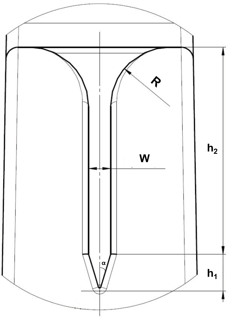
  9. 9.Roux, S. et al. Multifunctional nanoparticles: from the detection of biomolecules to the therapy. Int. J. Nanotechnol. 7, 781–801 (2010).ADS CAS Article Google Scholar 
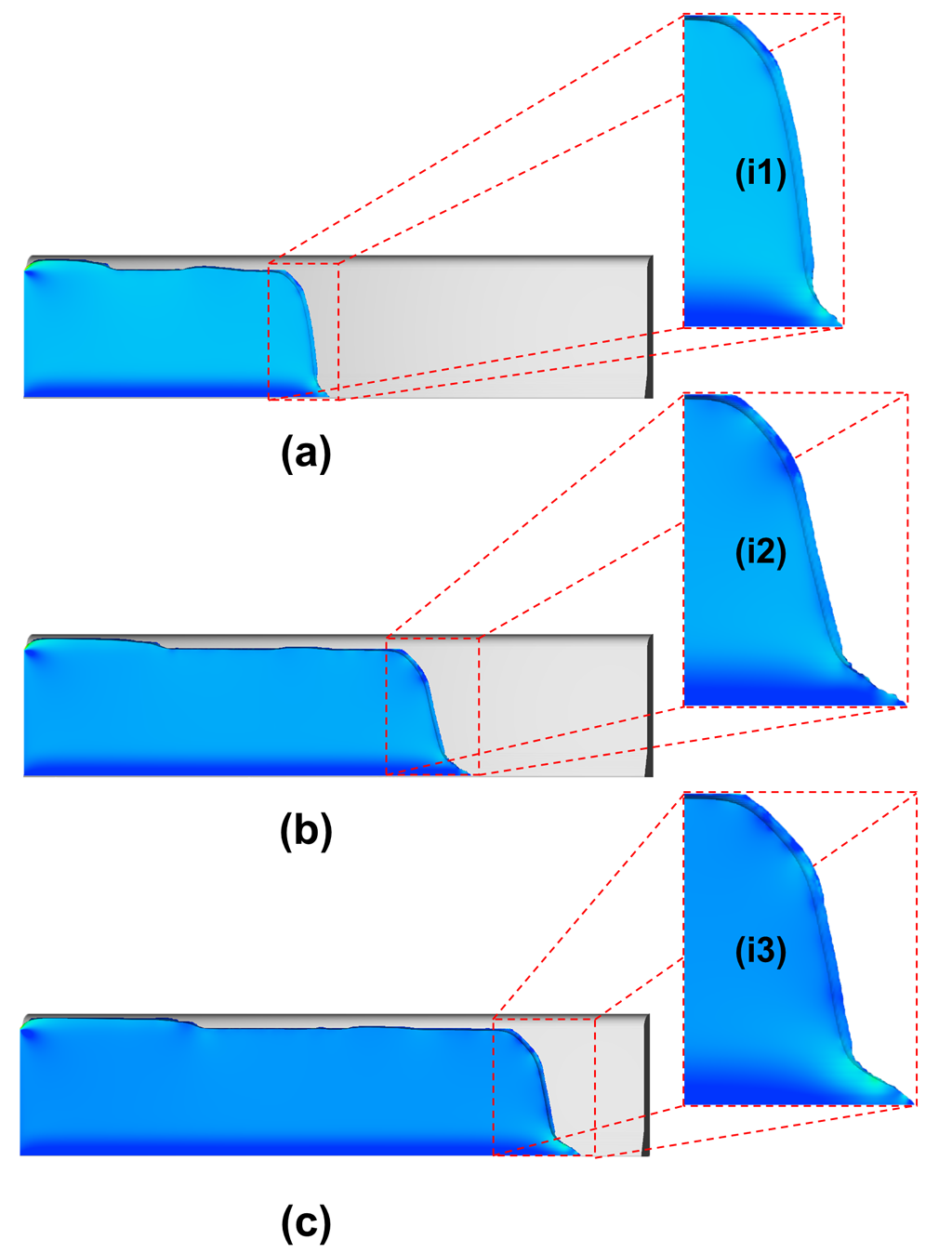
  10. 10.Gómez-Pastora, J., Bringas, E., Lázaro-Díez, M., Ramos-Vivas, J. & Ortiz, I. In Drug Delivery Systems (Stroeve, P. & Mahmoudi, M. ed) 207–244 (World Scientific, 2017).
  11. 11.Selmi, M., Gazzah, M. H. & Belmabrouk, H. Optimization of microfluidic biosensor efficiency by means of fluid flow engineering. Sci. Rep. 7(1), 5721 (2017).ADS Article Google Scholar 
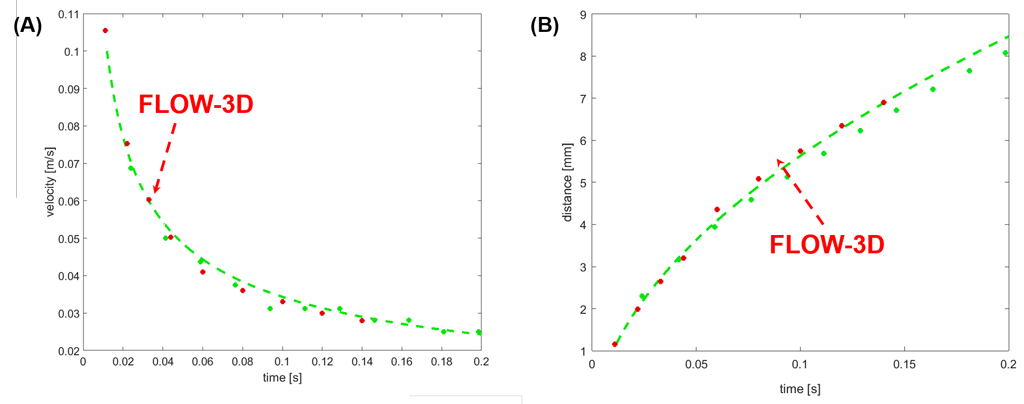
  12. 12.Gómez-Pastora, J., González-Fernández, C., Fallanza, M., Bringas, E. & Ortiz, I. Flow patterns and mass transfer performance of miscible liquid-liquid flows in various microchannels: Numerical and experimental studies. Chem. Eng. J. 344, 487–497 (2018).Article Google Scholar 
  13. 13.Pamme, N. Magnetism and microfluidics. Lab Chip 6, 24–38 (2006).CAS Article Google Scholar 
  14. 14.Alorabi, A. Q. et al. On-chip polyelectrolyte coating onto magnetic droplets – towards continuous flow assembly of drug delivery capsules. Lab Chip 17, 3785–3795 (2017).CAS Article Google Scholar 
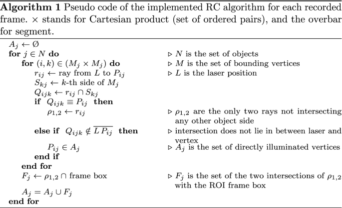
  15. 15.Gómez-Pastora, J. et al. Analysis of separators for magnetic beads recovery: from large systems to multifunctional microdevices. Sep. Purif. Technol. 172, 16–31 (2017).Article Google Scholar 
  16. 16.Tarn, M. D. & Pamme, N. On-chip magnetic particle-based immunoassays using multilaminar flow for clinical diagnosis. Methods Mol. Biol. 1547, 69–83 (2017).CAS Article Google Scholar 
  17. 17.Lv, C. et al. Integrated optofluidic-microfluidic twin channels: toward diverse application of lab-on-a-chip systems. Sci. Rep. 6, 19801 (2016).ADS CAS Article Google Scholar 
  18. 18.Gómez-Pastora, J. et al. Magnetic bead separation from flowing blood in a two-phase continuous-flow magnetophoretic microdevice: theoretical analysis through computational fluid dynamics simulation. J. Phys. Chem. C 121, 7466–7477 (2017).Article Google Scholar 
  19. 19.Furlani, E. P. Magnetic biotransport: analysis and applications. Materials 3, 2412–2446 (2010).ADS CAS Article Google Scholar 
  20. 20.Khashan, S. A. & Furlani, E. P. Effects of particle–fluid coupling on particle transport and capture in a magnetophoretic microsystem. Microfluid. Nanofluid. 12, 565–580 (2012).Article Google Scholar 
  21. 21.Modak, N., Datta, A. & Ganguly, R. Cell separation in a microfluidic channel using magnetic microspheres. Microfluid. Nanofluid. 6, 647–660 (2009).CAS Article Google Scholar 
  22. 22.Furlani, E. P., Sahoo, Y., Ng, K. C., Wortman, J. C. & Monk, T. E. A model for predicting magnetic particle capture in a microfluidic bioseparator. Biomed. Microdevices 9, 451–463 (2007).CAS Article Google Scholar 
  23. 23.Furlani, E. P. & Sahoo, Y. Analytical model for the magnetic field and force in a magnetophoretic microsystem. J. Phys. D: Appl. Phys. 39, 1724–1732 (2006).ADS CAS Article Google Scholar 
  24. 24.Tarn, M. D. et al. The importance of particle type selection and temperature control for on-chip free-flow magnetophoresis. J. Magn. Magn. Mater. 321, 4115–4122 (2009).ADS CAS Article Google Scholar 
  25. 25.Fonnum, G., Johansson, C., Molteberg, A., Morup, S. & Aksnes, E. Characterisation of Dynabeads® by magnetization measurements and Mössbauer spectroscopy. J. Magn. Magn. Mater. 293, 41–47 (2005).ADS CAS Article Google Scholar 
  26. 26.Xue, W., Moore, L. R., Nakano, N., Chalmers, J. J. & Zborowski, M. Single cell magnetometry by magnetophoresis vs. bulk cell suspension magnetometry by SQUID-MPMS – A comparison. J. Magn. Magn. Mater. 474, 152–160 (2019).ADS CAS Article Google Scholar 
  27. 27.Moore, L. R. et al. Continuous, intrinsic magnetic depletion of erythrocytes from whole blood with a quadrupole magnet and annular flow channel; pilot scale study. Biotechnol. Bioeng. 115, 1521–1530 (2018).CAS Article Google Scholar 
  28. 28.Furlani, E. P. & Xue, X. Field, force and transport analysis for magnetic particle-based gene delivery. Microfluid Nanofluid. 13, 589–602 (2012).CAS Article Google Scholar 
  29. 29.Furlani, E. P. & Xue, X. A model for predicting field-directed particle transport in the magnetofection process. Pharm. Res. 29, 1366–1379 (2012).CAS Article Google Scholar 
  30. 30.Furlani, E. P. Permanent Magnet and Electromechanical Devices; MaterialsAnalysis and Applications, (Academic Press, 2001).
  31. 31.Balachandar, S. & Eaton, J. K. Turbulent dispersed multiphase flow. Annu. Rev. Fluid Mech. 42, 111–133 (2010).ADS Article Google Scholar 
  32. 32.Wakaba, L. & Balachandar, S. On the added mass force at finite Reynolds and acceleration number. Theor. Comput. Fluid. Dyn. 21, 147–153 (2007).Article Google Scholar 
  33. 33.White, F. M. Viscous Fluid Flow, (McGraw-Hill, 1974).
  34. 34.Rietema, K. & Van Den Akker, H. E. A. On the momentum equations in dispersed two-phase systems. Int. J. Multiphase Flow 9, 21–36 (1983).Article Google Scholar 
  35. 35.Furlani, E. P. & Ng, K. C. Analytical model of magnetic nanoparticle transport and capture in the microvasculature. Phys. Rev. E 73, 1–10 (2006).Article Google Scholar 
  36. 36.Eibl, R., Eibl, D., Pörtner, R., Catapano, G. & Czermak, P. Cell and Tissue Reaction Engineering, (Springer, 2009).
  37. 37.Gómez-Pastora, J. et al. Computational modeling and fluorescence microscopy characterization of a two-phase magnetophoretic microsystem for continuous-flow blood detoxification. Lab Chip 18, 1593–1606 (2018).Article Google Scholar 
  38. 38.Khashan, S. A. & Furlani, E. P. Scalability analysis of magnetic bead separation in a microchannel with an array of soft magnetic elements in a uniform magnetic field. Sep. Purif. Technol. 125, 311–318 (2014).CAS Article Google Scholar 
  39. 39.Hirt, C. W. & Sicilian, J. M. A porosity technique for the definition of obstacles in rectangular cell meshes. ProcFourth International ConfShip Hydro., National Academic of Science, Washington, DC., (1985).
  40. 40.Crank, J. Free and Moving Boundary Problems, (Oxford University Press, 1984).
  41. 41.Bruus, H. Theoretical Microfluidics, (Oxford University Press, 2008).
  42. 42.Liang, L. & Xuan, X. Diamagnetic particle focusing using ferromicrofluidics with a single magnet. Microfluid. Nanofluid. 13, 637–643 (2012).

Author information

  1. Edward P. Furlani is deceased.

Affiliations

  1. Department of Chemical and Biomolecular Engineering, ETSIIT, University of Cantabria, Avda. Los Castros s/n, 39005, Santander, SpainJenifer Gómez-Pastora, Eugenio Bringas & Inmaculada Ortiz
  2. Flow Science, Inc, Santa Fe, New Mexico, 87505, USAIoannis H. Karampelas
  3. Department of Chemical and Biological Engineering, University at Buffalo (SUNY), Buffalo, New York, 14260, USAEdward P. Furlani
  4. Department of Electrical Engineering, University at Buffalo (SUNY), Buffalo, New York, 14260, USAEdward P. Furlani
Fig. 12. Comparison of simulation results with experimental data for a flow rate of water = Ql=15 ml/hr and a flow rate of air = Qg =3 ml/hr.

Simulation of Droplet Dynamics and Mixing in Microfluidic Devices using a VOF-Based Method

Abstract

This paper demonstrates that the Volume of Fluid (TruVOF) method in FLOW-3D (a general purpose CFD software) is an effective tool for studying droplet dynamics and mixing in microfluidic devices. The first example studied is a T-junction where flow patterns for both droplet generation and passive mixing are analyzed. The second example studied is a co-flowing device where the formation and breakup of bubbles is simulated. The effect of viscosity on bubble formation is also analyzed. For a T-junction the bubble size is corroborated with experimental data. Both the bubble size and frequency are studied and corroborated with experimental data for a co-flowing device. The third example studied is the electrowetting phenomenon observed in a small water droplet resting on a dielectric material. The steady-state contact angle is plotted against the voltage applied. The results are compared with both the Young-Lippmann curve and experimental results. 

이 논문은 FLOW-3D (범용 CFD 소프트웨어)의 유체 부피 (TruVOF) 방법이 미세 유체 장치에서 액적 역학 및 혼합을 연구하는데 효과적인 도구임을 보여줍니다.

연구된 첫 번째 예는 액적 생성 및 수동 혼합에 대한 흐름 패턴이 분석되는 T- 접합입니다. 연구된 두 번째 예는 기포의 형성 및 분해가 시뮬레이션 되는 동시 유동 장치입니다.

기포 형성에 대한 점도의 영향도 분석됩니다. T 접합의 경우 기포 크기는 실험 데이터로 확증됩니다. 기포 크기와 빈도 모두 공동 유동 장치에 대한 실험 데이터로 연구되고 확증됩니다.

연구된 세 번째 예는 유전 물질 위에 놓인 작은 물방울에서 관찰 된 전기 습윤 현상입니다. 정상 상태 접촉각은 적용된 전압에 대해 플롯됩니다. 결과는 Young-Lippmann 곡선 및 실험 결과와 비교됩니다.

Simulation of Droplet Dynamics and Mixing in Microfluidic Devices using a VOF-Based Method Fig 1
Simulation of Droplet Dynamics and Mixing in Microfluidic Devices using a VOF-Based Method Fig 2

References

Formation of bubbles in a simple co-flowing micro-channel

SaveAlertResearch FeedFormation of droplets and bubbles in a microfluidic T-junction-scaling and mechanism of break-up.

SaveAlertResearch FeedCreating, transporting, cutting, and merging liquid droplets by electrowetting-based actuation for digital microfluidic circuits,

SaveAlertResearch FeedFLOW DEVELOPMENT OF CO-FLOWING STREAMS IN RECTANGULAR MICRO-CHANNELS

SaveAlertResearch FeedA microfluidic system for controlling reaction networks in time.

SaveAlertResearch FeedElectrowetting: from basics to applications

SaveAlertResearch FeedVolume of fluid (VOF) method for the dynamics of free boundaries

Figure 1. Cross-sectional dimensions of a V-groove channel

Modeling Open Surface Microfluidics

개방형 표면 미세 유체 모델링

Open surface microfluidic systems are becoming increasingly popular in the fields of biology, biotechnology, medicine, point-of-care (POC) and home care systems. The design of such systems usually involves fluid being transported by capillary forces. Capillarity can enhance fluid transport for small volumes of fluid and can provide a reliable alternative to micro-scale pumping mechanisms. Advantages of capillary systems include:

  • Low cost due to easy and fast fabrication
  • User friendliness due to the simplicity of their design
  • Increased portability ensured by the capillary actuation of fluids
  • Enhanced accessibility caused by the open-surface nature of their design
  • Complete elimination of air bubbles guaranteed by the uniformly moving fluid front

For these reasons, open capillary systems are the preferred design option for various POC systems.

개방형 표면 미세 유체 시스템은 생물학, 생명 공학, 의학, POC (Point-of-Care) 및 홈 케어 시스템 분야에서 점점 인기를 얻고 있습니다. 이러한 시스템의 설계에는 일반적으로 모세관 힘에 의해 유체가 운반됩니다. 모세관은 소량의 유체에 대한 유체 수송을 향상시킬 수 있으며 마이크로 규모 펌핑 메커니즘에 대한 신뢰할 수있는 대안을 제공 할 수 있습니다. 모세관 시스템의 장점은 다음과 같습니다.

  • 쉽고 빠른 제작으로 인한 저렴한 비용
  • 디자인의 단순성으로 인한 사용자 편의성
  • 유체의 모세관 작동으로 인한 휴대 성 향상
  • 디자인의 개방형 특성으로 인한 접근성 향상
  • 균일하게 움직이는 유체 전면으로 보장되는 기포의 완전한 제거

이러한 이유로 개방형 모세관 시스템은 다양한 POC 시스템에서 선호되는 설계 옵션입니다.

모세관 흐름의 시작 조건

V 홈 치수
그림 1. V 홈 채널의 단면 치수 : W = 150 μm, h1 = 300 μm, h2 = 1200 μm, α = 14.5ο.

University at Buffalo와 University of Grenoble의 연구원들의 최근 논문에서 마이크로 그루브가 잠재적으로 모세관 효과를 향상시킬 수있는 방법을 보여주었습니다 [1]. 이 논문의 결과를 바탕으로, FLOW-3D를 사용하여 평행 한 플레이트로 대체 된 좁은 V- 홈 마이크로 채널 내부 유체의 자발적 모세관 흐름 (SCF)에 대한 사례 연구를 논의 할 것  입니다. 모세관 흐름의 시작에 대한 특정 조건이 충족되면 혈류를 모니터링하기위한 POC 시스템의 설계를 위해 전혈과 같은 점성 유체를 사용해도 큰 유체 속도를 얻을 수 있습니다.

모세관 흐름의 조건은 Gibbs 자유 에너지의 최소화를 기반으로 한 정적 접근 방식을 사용하여 이론적으로 설정할 수 있습니다. 보다 구체적으로, 입구 압력이 0 일 때 모세관 흐름이 시작되는 조건은 다음과 같습니다.

(수식 1)           pF/pW < cos⁡ θ

여기서  θ  는 영 접촉각이고  F  및  W  는 각각 유동의 임의 단면에서 자유 및 습식 둘레입니다. 그림 1에 표시된 것과 같은 반각 α 를 갖는 V- 홈 마이크로 채널의  경우 몇 가지 수학적 조작 후 eq. 1은 다음과 같이 다시 작성할 수 있습니다.

(수식 2)         sin α = cos⁡ θ

우리의 경우  α  ≈ 14.5 ο 가 있으므로 모세관 흐름의 조건은  θ  <75.5 o 입니다.

FLOW-3D 에서 시뮬레이션

정적 접근 방식이 SCF의 시작에 관한 중요한 정보를 제공하지만 수치 접근 방식은 현장 진료 장치에서 유동 역학을 연구하는 데 더 적합합니다. 접촉각이 37 °  이고 전혈의 유체 특성 을 갖는 V- 홈 마이크로 채널에 대해 CFD 분석을 수행했습니다 . 혈액의 점도는 거의 일정하기 때문에 흐름 체제는 뉴턴으로 간주됩니다 [1]. 유체 운동이 모세관 효과에 의해서만 발생하도록 모든 경계와 계산 영역 전체에 균일 한 주변 압력이 적용되었습니다. 시뮬레이션은 처음 4mm의 유체 이동을 포함하는 초기 시뮬레이션과 4mm에서 8mm의 유체 이동을 예측하는 재시작 시뮬레이션의 두 부분으로 나뉩니다.

결과 및 검증

처음 8mm 이동에 대한 유동 역학은 그림 2에 나와 있습니다.이 그림은 세 가지 다른 시간에 슬롯에서 전진 인터페이스의 모양을 보여줍니다. 필라멘트 (Concus-Finn 필라멘트)의 점진적인 확장은 주 흐름보다 앞서 볼 수 있습니다.

모세관 흐름 시뮬레이션
그림 2. 세 가지 다른 시간에서 FLOW-3D를 사용하여 진행하는 모세관 흐름의 동적 계산 : (a) 0.04, (b) 0.07 및 (c) 0.11 초와 삽입물 (i1), (i2) 및 (i3) Concus-Finn 필라멘트의 진화 [1].

분석, 수치 및 실험 결과 간의 비교는 그림 3에 나와 있습니다. 수치 예측과 실험 간에는 탁월한 일치가 있습니다. 분석 솔루션도 플롯되었지만 채널 하단에있는 Concus – Finn 필라멘트의 효과가 고려되지 않았기 때문에 수치 및 실험 결과에 대한 유효한 비교를 나타내지 않을 수 있습니다.

모세관 흐름 검증
그림 3. (A) 시간의 함수로서 채널의 속도. 빨간색 점 : FLOW-3D 시뮬레이션 (중간 높이에서); 녹색 점 : 실험 관찰 (채널 중앙 높이); 파선 녹색 선 : 하단 V 홈의 효과를 무시한 분석 속도. (B) 시간의 함수로서 액체 전면의 원점으로부터의 거리. 빨간색 점 : FLOW-3D 시뮬레이션 (중간 높이에서); 녹색 점 : 실험 관찰 (채널 중앙 높이); 파선 녹색 선 : 하단 V 홈의 효과를 무시한 분석 속도 [1].

전혈 이외에도 식용 색소로 착색 한 물과 점성이 높은 알기 네이트 용액을 포함하여 장치가 고점도 유체를 이동시킬 수있는 가능성을 테스트하는 등 다양한 유체를 연구했습니다. 혈액과 같은 고점도 액체는 1 초 이내에 이동할 수 있습니다 (아래 애니메이션 참조).https://www.youtube.com/embed/v4OYoHStJ1w?controls=1&rel=0&playsinline=0&modestbranding=0&autoplay=0&enablejsapi=1&origin=https%3A%2F%2Fwww.flow3d.com&widgetid=1

사례 연구는 상대적으로 큰 점도 (물의 4 배)를 갖는 전혈의 경우 최대 7.5cm / s의 속도를 달성했음을 보여줍니다. 실험 결과 및  FLOW-3D  예측에 따라 전체 채널은 0.2 초 이내에 혈액으로 채워졌습니다. FLOW-3D  시뮬레이션 결과는 실험 관찰 결과와 매우 일치하며, V-groove 내부의 거리에 따라 속도가 감소하지만 장치의 전체 길이에 걸쳐 중요 함을 나타냅니다.

참고 문헌

  1. Berthier, J., K. Brakke, E. P. Furlani, I. H. Karampelas, and G. Delapierre. “Open-surface microfluidics.” In Proceedings of the Nanotech International Conference, pp. 15-19. 2014.
  2. Hirt, Cyril W., and Billy D. Nichols. “Volume of fluid (VOF) method for the dynamics of free boundaries.” Journal of computational physics 39, no. 1 (1981): 201-225.
  3. Rajaratnam, N., and M. R. Chamani. “Energy loss at drops.” Journal of Hydraulic Research 33, no. 3 (1995): 373-384.
A new dynamic masking technique for time resolved PIV analysis

A new dynamic masking technique for time resolved PIV analysis

시간 분해 PIV 분석을위한 새로운 동적 마스킹 기술

물체 가시성을 허용하기 위해 형광 코팅과 결합 된 새로운 프리웨어 레이 캐스팅 도구

Journal of Visualization ( 2021 ) 이 기사 인용

Abstract

Time resolved PIV encompassing moving and/or deformable objects interfering with the light source requires the employment of dynamic masking (DM). A few DM techniques have been recently developed, mainly in microfluidics and multiphase flows fields. Most of them require ad-hoc design of the experimental setup, and may spoil the accuracy of the resulting PIV analysis. A new DM technique is here presented which envisages, along with a dedicated masking algorithm, the employment of fluorescent coating to allow for accurate tracking of the object. We show results from measurements obtained through a validated PIV setup demonstrating the need to include a DM step even for objects featuring limited displacements. We compare the proposed algorithm with both a no-masking and a static masking solution. In the framework of developing low cost, flexible and accurate PIV setups, the proposed algorithm is made available through a freeware application able to generate masks to be used by an existing, freeware PIV analysis package.

광원을 방해하는 이동 또는 변형 가능한 물체를 포함하는 시간 해결 PIV는 동적 마스킹 (DM)을 사용해야 합니다. 주로 미세 유체 및 다상 흐름 분야에서 몇 가지 DM 기술이 최근 개발되었습니다. 대부분은 실험 설정의 임시 설계가 필요하며 결과 PIV 분석의 정확도를 떨어 뜨릴 수 있습니다. 여기에는 전용 마스킹 알고리즘과 함께 형광 코팅을 사용하여 물체를 정확하게 추적 할 수있는 새로운 DM 기술이 제시되어 있습니다. 제한된 변위를 특징으로 하는 물체에 대해서도 DM 단계를 포함해야 하는 필요성을 보여주는 검증 된 PIV 설정을 통해 얻은 측정 결과를 보여줍니다. 제안 된 알고리즘을 no-masking 및 static masking 솔루션과 비교합니다. 저비용, 유연하고 정확한 PIV 설정 개발 프레임 워크에서 제안 된 알고리즘은 기존 프리웨어 PIV 분석 패키지에서 사용할 마스크를 생성 할 수 있는 프리웨어 애플리케이션을 통해 사용할 수 있습니다.

Keywords

  • Time resolved PIV, Dynamics masking, Image processing, Vibration inducers, Fluorescent coating

그래픽 개요

소개

PIV (입자 영상 속도계)의 사용은 70 년대 후반 (Archbold 및 Ennos 1972 )이 반점 계측의 확장 (Barker and Fourney 1977 ) 으로 도입된 이래 실험 유체 역학에서 중심적인 역할을 했습니다 . PIV 기술의 기본 아이디어는 유체에 주입된 입자의 속도를 측정하여 유동장을 재구성하는 것입니다. 입자의 크기와 밀도는 확실하게 선택되고 유동을 만족스럽게 따르게 됩니다.

흐름은 레이저 / LED 소스를 통해 조명되고 입자에 의해 산란 된 빛은 추적을 허용합니다. 독자는 리뷰 작품 Grant ( 1997 ), Westerweel et al. ( 2013 년)에 대한 자세한 설명을 참조하십시오. 기본 2D 기술은 고유한 설정으로 발전했으며, 가장 진보 된 것은 단일 / 다중 평면 입체 PIV (Prasad 2000 ) 및 체적 / 단층 PIV (Scarano 2013 )입니다. 광범위한 유동장의 비 침습적 측정이 필요한 산업 및 연구 응용 분야에서 광범위하게 사용되었습니다.

조사된 유동장이 단단한 서있는 경계의 영향을 받는 경우 정적 마스킹 (SM) 접근 방식을 사용하여 PIV 분석을 수행하는 영역에서 솔리드 객체와 그림자가 차지하는 영역을 빼기 위해 주의를 기울여야 합니다. 실제로 이러한 영역에서는 파종 입자를 식별 할 수 없으므로 유속 재구성을 수행 할 수 없습니다. 제대로 처리되지 않으면 이 마스킹 단계는 잘못된 예측으로 이어질 수 있으며, 불행히도 그림자 영역 경계의 근접성에 국한되지 않습니다.

PIV 기술은 획득 프레임 속도를 관심있는 시간 척도로 조정하여 정상 상태 또는 시간 변화 흐름에 적용 할 수 있습니다. 시간의 가변성이 고체 물체의 위치 / 모양과 관련된 경우 이미지를 동적으로 마스킹하기 위해 추가 노력이 필요합니다. 고체 물체뿐만 아니라 다른 유체 단계도 가려야한다는 점에 유의해야합니다 (Foeth et al. 2006). 

이 프로세스는 고체 물체의 움직임이 선험적으로 알려진 경우 비교적 쉬우므로 SM 알고리즘에 대한 최소한의 수정이 목적에 부합 할 수 있습니다. 그러나 고체 물체의 위치 및 / 또는 모양이 알려지지 않은 방식으로 시간에 따라 변할 경우 물체를 동적으로 추적 할 수 있는 마스킹 기술이 필요합니다. PIV 분석을위한 동적 마스킹 (DM) 접근 방식은 현재 상당한 주목을 받고 있습니다 (Sanchis and Jensen 2011 , Masullo 및 Theunissen 2017 , Anders et al. 2019 ) . 시간 분해 PIV 시스템의 확산 덕분에 고속 카메라의 가용성이 높아집니다. 

DM 기술의 주요 발전은 마이크로 PIV 분야에서 비롯됩니다 (Lindken et al. 2009) 마이크로 및 나노 스위 머 (Ergin et al. 2015 ) 및 다상 흐름 (Brücker 2000 , Khalitov 및 Longmire 2002 ) 주변의 유동장을 조사 하려면 정확하고 유연한 알고리즘이 필요합니다. DM 기술은 상용 PIV 분석 소프트웨어 패키지 (TSI Instruments 2014 , DantecDynamics 2018 )에 포함되어 있습니다. 최근 개발 (Vennemann 및 Rösgen 2020 )은 신경망 자동 마스킹 기술의 적용을 예상하지만, 네트워크를 훈련하려면 합성 데이터 세트를 생성해야합니다.

많은 알고리즘은 이미지 처리 기술을 사용하여 개체를 추적하며, 대부분 사용자는 획득 한 이미지에서 추적 할 개체를 강조 표시 할 수있는 임시 실험 설정을 개발해야합니다. 따라서 실험 설정의 설계는 알고리즘의 최종 정확도에 영향을줍니다.

몇 가지 해결책을 구상 할 수 있습니다. 다음에서는 간단한 2D PIV 설정을 참조하지만 대부분의 고려 사항은 더 복잡한 설정으로 확장 할 수 있습니다. PIV 설정에서 객체를 쉽고 정확하게 추적 할 수 있도록 렌더링하는 가장 간단한 방법은 일반적으로 PIV 레이저 시트에 대략 수직 인 카메라를 향한 반사를 최대화하는 방향을 가리키는 추가 광원을 사용하여 조명하는 것입니다. 이 순진한 솔루션과 관련된 주요 문제는 PIV의 ROI (관심 영역)를 비추 지 않고는 광원을 움직이는 물체에만 겨냥하는 것이 사실상 불가능하여 시딩에 의해 산란 된 레이저 광 사이의 명암비를 감소 시킨다는 것입니다. 입자와 어두운 배경.

카메라의 프레임 속도가 높을수록 센서에 닿는 빛의 양이 적다는 사실로 인해 상황이 가혹 해집니다. 고체 물체의 움직임과 유동 입자가 모두 사용 된 설정의 획득 속도에 비해 충분히 느리다면, 가능한 해결책은 레이저 펄스 쌍 사이에 단일 확산 광 샷을 삽입하는 것입니다 (반드시 대칭 삽입은 아님). 그리고 카메라 샷을 둘 모두에 동기화합니다. 각 레이저 커플에서 물체의 위치는 확산 광에 의해 생성 된 이전 샷과 다음 샷의 두 위치를 보간하여 결정될 수 있습니다. 이 접근 방식에는 레이저, 카메라 및 빛을 제어 할 수있는 동기화 장치가 필요합니다.

이 문제에 대한 해결책이 제안되었으며 유체 인터페이스 (Foeth et al. 2006 ; Dussol et al. 2016 ) 의 밝은 반사를 활용 하여 이미지에서 많은 양의 산란 레이저 광을 획득 할 수 있습니다. 고체 표면에는 효과를 높이기 위해 반사 코팅이 제공 될 수 있습니다. 그런 다음 물체는 비정상적으로 큰 입자로 식별되고 경계를 쉽게 추적 할 수 있습니다. 이 솔루션의 단점은 물체 표면에서 산란 된 빛이 레이저 시트에 있지 않은 많은 시딩 입자를 비추어 PIV 분석의 정확도를 점진적으로 저하 시킨다는 것입니다.

위의 접근 방식의 개선은 다른 파장 의 두 번째 동일 평면 레이저 시트 (Driscoll et al. 2003 )를 사용합니다. 첫 번째 레이저 파장을 중심으로 한 좁은 반사 대역. 전체 설정은 매우 비쌀 수 있습니다. 파장 방출의 차이를 이용하여 설정을 저렴하게 만들 수 있습니다. 서로 다른 필터가 장착 된 두 대의 카메라를 적용하면 인터페이스로부터의 반사와 독립적으로 형광 시드 입자를 식별 할 수 있습니다 (Pedocchi et al. 2008 ).

객체의 변위가 작을 때 기본 솔루션은 실제 시간에 따라 변하는 음영 영역에 가장 근접한 하나의 정적 마스크를 추출하는 것입니다. 일반적인 경험 법칙은 예상되는 음영 영역보다 약간 더 크게 마스크를 그려 분석에 포함 된 조명 영역의 양을 단순화하고 최소화하는 것 사이의 최상의 균형을 찾는 것입니다.

본 논문에서는 PIV 분석을위한 DM 문제에 대한 새로운 실험적 접근법을 제안합니다. 우리의 방법은 형광 페인팅을 사용하여 물체를 쉽게 추적 할 수 있도록 하는 기술과 시변 마스크를 생성 할 수있는 특정 오픈 소스 알고리즘을 포함합니다. 이 접근법은 레이저 광에 불투명 한 물체의 큰 변위를 허용함으로써 효과적인 것으로 입증되었습니다. 

우리의 방법인 NM (no-masking)과 SM (static masking) 접근 방식을 비교합니다. 우리의 접근 방식의 타당성을 입증하는 것 외에도 이 백서는 마스킹 단계가 정확한 결과를 얻기 위해 가장 중요하다는 것을 확인합니다. 실제로 물체의 변위가 무시할 수 없는 경우 DM에 대한 리조트는 필수이며 SM 접근 방식은 음영 처리 된 영역의 주변 환경에 국한되지 않는 부정확성을 유발합니다. 

논문의 구조는 다음과 같습니다. 먼저 형광 코팅 기술과 마스킹 소프트웨어를 설명하는 제안된 접근법의 근거를 소개합니다. 그런 다음 PIV 설정에 대한 설명 후 두 벤치 마크 사례를 통해 전체 PIV 체인 분석의 신뢰성을 평가합니다. 그런 다음 제안 된 DM 방법의 결과를 NM 및 SM 솔루션과 비교합니다. 마지막으로 몇 가지 결론이 도출됩니다.

행동 양식

제안 된 DM 기술은 PIV 분석을 위해 캡처 한 동일한 이미지에서 쉽고 정확한 추적 성을 허용하기 위해 움직이는 물체 표면의 형광 코팅을 구상합니다. 물체가 가시화되면 특정 알고리즘이 물체 추적을 수행하고 레이저 위치가 알려지면 (그림 1 참조  ) 음영 영역의 마스킹을 수행합니다.

형광 코팅

코팅은 구조적 매트릭스 에 시판되는 형광 분말 (fluorescein (Taniguchi and Lindsey 2018 ; Taniguchi et al. 2018 )) 의 분산액으로 구성됩니다 . 단단한 물체의 경우 매트릭스는 폴리 에스터 / 에폭시 (대상 재료와의 화학적 호환성에 따라) 투명 수지 일 수 있습니다. 변형 가능한 물체의 경우 매트릭스는 투명한 실리콘 고무로 만들 수 있습니다. 형광 코팅 된 물체는 실행 중에 지속적으로 빛을 방출하기 위해 실험 전에 충분히 오랫동안 조명을 비춰 야합니다. 우리는 4W LED 소스 (그림 2 에서 볼 수 있음)에 20 초 긴 노출이  실험 실행 (몇 초)의 짧은 기간 동안 일관된 형광 방출을 제공하기에 충분하다는 것을 발견했습니다.

우리 실험에서 물체와 입자 크기 사이의 상당한 차이를 감안할 때 전자를 식별하는 것은 간단합니다. 그림  3 은 씨 뿌리기 입자와 물체 모양이 서로 다른 세 번에 겹쳐진 모습을 보여줍니다 (색상은 다른 순간을 나타냄).

대신, 이러한 크기 기반 분류가 가능하지 않은 경우 입자와 물체의 파장을 분리해야합니다. 이러한 분리는 시드 입자에 의해 산란 된 빛과 현저하게 다른 파장에서 방출되는 형광 코팅을 선택하여 달성 할 수 있습니다. 또는 레이저에서 멀리 떨어진 대역에서 방출되는 형광 입자를 이용하는 것 (Pedocchi et al. 2008 ). 두 경우 모두 컬러 이미지 획득의 채널 분리 또는 멀티 카메라 설정의 애드혹 필터링은 물체 식별을 크게 촉진 할 수 있습니다. 우리의 경우에는 그러한 파장 분리를 달성 할 필요가 없습니다. 실제로 형광 코팅의 방출 스펙트럼의 피크는 540nm입니다 (Taniguchi and Lindsey 2018 ; Taniguchi et al. 2018), 사용 된 레이저의 532 nm에 매우 가깝습니다.

마스킹 소프트웨어

DM 용으로 개발 된 알고리즘 은 무료 PIV 분석 패키지 PIVlab (Thielicke 2020 , Thielicke 및 Stamhuis 2014 ) 과 함께 작동하도록 고안된 오픈 소스 프리웨어 GUI 기반 도구 (Prestininzi 및 Lombardi 2021 )입니다. 이것은 세 단계의 순차적 실행으로 구성됩니다 (그림 1 에서 a–b–c라고 함 ). 첫 번째 단계 (a)는 장면에서 레이저 위치를 찾는 데 사용됩니다 (즉, 소스의 좌표를 계산합니다. 장애물에 부딪히는 빛); 두 번째 항목 (b)은 개체 위치를 추적하고 각 프레임의 음영 영역을 계산합니다. 세 번째 항목 (c)은 추적 된 개체 영역과 음영 처리 된 개체 영역을 PIV 알고리즘을위한 단일 마스크로 병합합니다.

각 단계에 대한 자세한 내용은 다음과 같습니다.

  1. (ㅏ)레이저 위치는 프레임 (즉, 획득 한 프레임의 시야 (FOV)) 내에서 가시적 일 수도 있고 아닐 수도 있습니다. 전자의 경우 사용자는 GUI에서 레이저 소스를 클릭하여 찾기 만하면됩니다. 후자의 경우, 사용자는 음영 영역의 경계에 속하는 두 개의 세그먼트 (두 쌍의 점)를 그리도록 요청받습니다. 그러면 FOV 외부에있는 레이저 위치가 두 선의 교차점으로 계산됩니다. 세그먼트로 구성됩니다. 개체 그림자는 ROI 프레임 상자에 도달하는 것으로 간주됩니다.
  2. (비)레이저 위치가 알려지면 물체 추적은 다음과 같이 수행됩니다. 각 프레임의 하나의 채널 (이 경우 RGB 색상 공간이 사용되기 때문에 녹색 채널이지만 GUI는 선호하는 채널을 지정할 수 있음)은 다음과 같습니다. 로컬 적응 임계 값을 사용하여 이진화 됨 (Bradley and Roth 2007), 후자는 이웃 주변의 로컬 평균 강도를 사용하여 각 픽셀에 대해 계산됩니다. 그런 다음 입자와 물체로 구성된 이진 이미지가 영역으로 변환됩니다. 우리 실험에 존재하는 유일한 장애물은 모든 입자에 비해 더 큰 크기를 기준으로 식별됩니다. 다른 전략은 이전에 논의되었습니다. 그런 다음 장애물 영역의 경계 다각형은 사용자 정의 포인트 밀도로 결정됩니다. 여기에서는 그림자 결정을 위해 광선 투사 (RC) 접근 방식을 채택했습니다. RC는 컴퓨터 그래픽을 기반으로하는 “경 운송 모델링”의 틀에 속합니다. 수치 적으로 정확한 그림자를 제공하기 때문에 여기에서 선택됩니다. 정확도는 떨어지지 만 주로 RC의 계산 부하를 줄이는 것을 목표로하는 몇 가지 다른 방법이 개발되었습니다.2015 ), 여기서 간략히 회상합니다. 각 프레임 (명확성을 위해 여기에 색인화되지 않음)에 대해 광선아르 자형나는 j아르 자형나는제이레이저 위치 L 에서 i 번째 정점 으로 캐스트됩니다.피나는 j피나는제이의 J 오브젝트의 경계 다각형 일; 목표는피나는 j피나는제이 하위 집합에 속 ㅏ제이ㅏ제이 레이저에 의해 직접 조명되는 경계 정점의 피나는 j피나는제이 에 추가됩니다 ㅏ제이ㅏ제이 만약 아르 자형나는 j아르 자형나는제이 적어도 한쪽을 교차 에스k j에스케이제이( j 번째 개체 경계 다각형 의 모든면에 걸쳐있는 k )피나는 j피나는제이 (그것이 교차로 큐나는 j k큐나는제이케이 레이저 위치와 정점 사이에 있지 않습니다. 피나는 j피나는제이). 두 개의 광선, 즉ρ1ρ1 과 ρ2ρ2추가면을 가로 지르지 않는는 저장됩니다.
  3. (씨)일단 정점 세트, 즉 ㅏ제이ㅏ제이 레이저에 의해 직접 비춰지고 식별되었으며 ROI 프레임 상자의 음영 부분은 후자와 교차하여 결정됩니다. ρ1ρ1 과 ρ2ρ2. 두 교차점은 다음에 추가됩니다.ㅏ제이ㅏ제이. 점으로 둘러싸인 영역ㅏ제이ㅏ제이 마침내 마스크로 변환됩니다.

레이저 소스가 여러 개인 경우 각각에 RC 알고리즘을 적용해야하며 음영 영역의 결합이 수행됩니다. 레이 캐스팅 절차의 의사 코드는 Alg에보고됩니다. 1.

그림
그림 1
그림 1

DM 검증

이 섹션에서는 제안 된 DM으로 수행 된 PIV 측정과 두 가지 다른 접근 방식, 즉 no-masking (NM)과 static masking (SM) 간의 비교를 제시합니다.

그림 2
그림 2
그림 3
그림 3

실험 설정

진동 유도기 (VI)의 성능을 분석하기 위해 PIV 설정을 설계하고 현재 DM 기술을 개발했습니다 (Curatolo et al. 2019 , 2020 ). 후자는 비 맥동 ​​유체 흐름에서 역류에 배치 된 캔틸레버의 규칙적이고 넓은 진동을 유도 할 수있는 윙렛입니다. 이러한 VI는 캔틸레버의 끝에 장착되며 (그림 2 참조   ) 진동 운동의 어느 지점에서든 캔틸레버의 중립 구성을 향해 양력을 생성 할 수있는 두 개의 오목한 날개가 있습니다.

VI는 캔틸레버 표면에 장착 된 압전 패치를 사용하여 고정 유체 흐름에서 기계적 에너지 추출을 향상시킬 수 있습니다. 그림 2 에서 강조된 날개의 전체 측면 가장자리는  Sect에 설명 된 사양에 따라 형광 페인트로 코팅되어 있습니다. 2.1 . 실험은 Roma Tre University 공학부 수력 학 실험실의 자유 표면 채널에서 수행됩니다. 10.8cm 길이의 캔틸레버는 채널의 중심선에 배치되고 상류로 향하며 수직-세로 평면에서 진동합니다. 세라믹 페 로브 스카이 트 (PZT) 압전 패치 (7××캔틸레버의 윗면에는 Physik Instrumente (PI)에서 만든 3cm)가 부착되어 있습니다. 흐름 유도 진동 하에서 변형으로 인해 AC 전압 차이를 제공합니다. VI 왼쪽 날개의 수직 중앙면에있는 2D 속도 필드는 수제 수중 PIV 장비를 통해 얻었습니다.각주1 연속파, 저비용, 저전력 (150mW), 녹색 (532nm) 레이저 빔이 2mm 두께의 부채꼴 시트에 퍼집니다.120∘120∘그림 2 와 같이 VI의 한쪽 날개를 절반으로 교차 합니다. 물은 평균 직경이 100 인 폴리 아미드 입자로 시드됩니다.μμm 및 1016 Kg / m의 밀도삼삼. 레이저 소스는 VI의 15cm 위쪽 (자유 표면 아래 약 4cm)과 VI의 하류 5cm에 경사지게 배치됩니다.5∘5∘상류. 위의 설정은 주로 날개의 후류를 조사하기 위해 고안되었습니다. 날개의 상류면과 하류 부분의 일부는 레이저 시트에 직접 맞지 않습니다. 레이저 시트에 수직으로 촬영하는 고속 상용 카메라 (Sony RX100 M5)를 사용하여 동영상을 촬영합니다. 후자는 1920의 프레임 크기로 500fps의 높은 프레임 속도 모드로 기록됩니다.×× 1080px, 나중에 더 작은 655로 잘림 ××이미지 분석 중에 분석 할 850px ROI. 시간 해결, 프리웨어, 오픈 소스, MatLab 용 PIV 분석 도구가 사용됩니다 (Thielicke and Stamhuis 2014 ). 이 도구는 질의 영역 (IA) 변형 (우리의 경우 64×× 64, 32 ×× 32 및 26 ××26). 각 패스에서 각 IA의 경계와 모서리에서 추가 변위 정보를 얻기 위해 인접한 IA 사이에 50 %의 중첩이 허용됩니다. 첫 번째 통과 후, 입자 변위 정보가 보간되어 IA의 모든 픽셀의 변위를 도출하고 그에 따라 변형됩니다.

시딩 입자 수 밀도는 첫 번째 패스에서 IA 당 약 5입니다. Keane과 Adrian ( 1992 )에 따르면 이러한 밀도 값은 95 % 유효한 탐지 확률을 보장합니다. IA는 프레임 커플 내에서 입자의 충분한 영구성을 보장하기 위해 크기가 조정됩니다. 분석 된 유동 역학은 0.4 ~ 0.7m / s 범위의 유동 속도를 특징으로합니다. 따라서 입자는 권장 최소값 인 2 프레임 (Keane and Adrian 1992 ) 보다 큰 약 3-4 프레임의 세 번째 패스 IA에 나타납니다 .

PIV 체인 분석 평가

사용 된 PIV 알고리즘의 정확성은 이전에 문헌에서 광범위하게 평가되었습니다 (예 : Guérin et al. ( 2020 ), Vennemann and Rösgen ( 2020 ), Mohammadshahi et al. ( 2020 ), Narayan et al. ( 2020 )). 그러나 PIV 측정의 물리적 일관성을 보장하기 위해 두 가지 벤치 마크 사례가 여기에 나와 있습니다.

첫 번째는 Sect에 설명 된 동일한 PIV 설정을 통해 측정 된 세로 유속의 수직 프로파일을 비교합니다. 3.1 분석 기준 용액이있는 실험 채널에서. 후자는 플로팅 트레이서로 수행되는 PTV (입자 추적 속도계) 측정을 통해 보정되었습니다. 분석 속도 프로파일은 Eq. 1 (Keulegan 1938 ).u ( z) =유∗[5.75 로그(지δ) +8.5];유(지)=유∗[5.75로그⁡(지δ)+8.5];(1)

여기서 u 는 수평 유속 성분, z 는 수직 좌표,δδ 침대 거칠기 및 V∗V∗ 균일 한 흐름 공식에 의해 주어진 것으로 가정되는 마찰 속도, 즉 유∗= U/ C유∗=유/씨; U 는 깊이 평균 유속이고 C 는 다음 과 같이 주어진 마찰 계수입니다.씨= 5.75로그( 13.3에프R / δ)씨=5.75로그⁡(13.3에프아르 자형/δ), R = 0.2아르 자형=0.2 m은 유압 반경이고 에프= 0.92에프=0.92유한 폭 채널의 형상 계수. 그림  4 는 4 초의 시간 창에 걸쳐 순간 값을 평균화하여 얻은 분석 프로필과 PIV 측정 간의 비교를 보여줍니다. 국부적 인 변동은 대략 0.5 초의 시간 척도에서 진화하는 것으로 밝혀졌습니다. PTV 결과에 가장 적합하면 다음과 같은 값이 산출됩니다.δ= 1δ=1cm, 베드 거칠기의 경우 Eq. 1 , 실험 채널 침대 표면의 실제 조건과 호환됩니다. VI의 휴지 구성 위치에서 유속의 분석 값은 그림에서 검은 색 십자가로 표시됩니다. 비교는 놀라운 일치를 보여 주므로 실험 설정과 PIV 알고리즘의 조합이 분석 된 설정에 대해 신뢰할 수있는 것으로 간주 될 수 있음을 증명합니다.

두 번째 벤치 마크는 VI 뒷면에 재 부착 된 흐름의 양을 비교합니다. 실제로 이러한 장치의 높은 캠버를 고려할 때 흐름은 하류 표면에서 분리되어 결국 다시 연결됩니다. 첨부 흐름을 나타내는 표면의 양 (Curatolo 외. 발견 2020 ) 흥미로운 압전 패치 (즉, 효율이 큰 경우에 더 빠르게 진동이 유발되는 것이다)에서 VI의 효율과 상관된다. 여기에서는 PIV 분석을 통해 측정 된 진동의 상사 점에서 재 부착 된 흐름의 길이를 CFD (전산 유체 역학) 상용 코드 FLOW-3D® (Flow Science 2019 )로 예측 한 길이와 비교하여 RANS를 해결합니다. 결합 식 (비어 스톡스 레이놀즈 평균) 케이 -ϵϵ구조화 된 그리드의 난류 폐쇄 (시뮬레이션을 위해 1mm 간격이 선택됨). 다운 스트림 측면의 흐름은 이러한 높은 캠버 VI를 위해 여러 위치에서 분리 및 재 부착됩니다. 이 벤치 마크에서 비교 된 양은 VI의 앞쪽 가장자리와 가장 가까운 흐름 재 부착 위치 사이의 호 길이입니다. 그림 5를 참조  하면 CFD 모델에 의해 예측 된 호의 길이는 측정 된 호의 길이보다 10 % 더 큽니다. 이 작업에 제시된 DM 기술을 사용하는 PIV 분석은 물리적으로 건전한 측정을 제공하는 것으로 입증됩니다. 후류의 유체 역학에 대한 자세한 분석과 VI의 전반적인 효율성과의 상관 관계는 현재 진행 중이며 향후 작업의 대상이 될 것입니다.

그림 4
그림 4
그림 5
그림 5

결과

그림 6을 참조하여  순간 유속 장의 관점에서 세 가지 접근법의 결과를 비교합니다. 선택한 순간은 진동의 상사 점에 해당합니다.

제안 된 DM (그림 6 의 패널 a  )은 부드러운 유동장을 생성하여 후류에서 일관된 소용돌이 구조를 나타냅니다.

NM 접근법 (그림 6 의 패널 b1  )도 후류의 와류 구조를 정확하게 예측하지만 음영 영역에서 대부분 부정확 한 값을 산출합니다. 또한 비교에서 합리적인 기준을 추론 할 수 없기 때문에 획득 한 유동장 의 사후 필터링이 실현 가능하지 않다는 것이 분명합니다 . 실제로 유속은 그림 6 의 패널 c1에서 볼 수 있듯이 가장 큰 오류가 생성되는 위치에서도 “합리적인”크기를 갖습니다. , DM 및 NM 접근 방식으로 얻은 속도 필드 간의 차이가 표시됩니다. 더욱이 후류에서 발생하는 매우 불안정한 소용돌이 운동이 이러한 위치에 가깝게 이동하기 때문에 그럴듯한 흐름 방향을 가정하더라도 필터링 기준을 공식화 할 수 없습니다. 모델러가 그러한 부정확성을 알고 있었다하더라도 NM 접근법은 “합리적”이지만 여전히 날개의 내부 현과 그 바로 아래에있는 유동장의 대부분은 부정확합니다. 이러한 행동은 매우 오해의 소지가 있습니다.

그림 6 의 패널 b2는  SM 접근법으로 얻은 유속 장을 보여주고 패널 c2는 SM과 DM 접근법으로 얻은 결과 간의 차이를 보여줍니다. SM 접근법은 NM 대응 물에 비해 전반적으로 더 나은 정확도를 명확하게 보여 주지만, 이는 레이저 소스의 위치가 진동 중에 음영 영역이 많이 움직이지 않기 때문입니다 (그림 3 참조). 한 번의 진동 동안 VI가 경험 한 최대 변위를 육안으로 검사합니다. 즉, 분석 된 사례의 경우 정적 마스크를 그리기위한 중립 구성을 선택하면 NM 접근 방식보다 낮은 오류를 얻을 수 있습니다. 더 큰 물체 변위를 포함하는 실험 설정은 NM이 일관되게 더 정확해질 수 있기 때문에 NM보다 SM의 우월성은 일반화 될 수 없음을 강조하고 싶습니다.

그림  6 은 분석 된 접근법에 의해 생성 된 차이를 철저히 보여 주지만 결과에 대한보다 정량적 인 평가를 제공하기 위해 오류의 빈도 분포를 계산했습니다. 그림 7 에서 이러한 분포를  살펴보면 SM 접근법이 NM보다 전체적인 예측이 더 우수하고 SM 분포가 더 정점에 있음을 확인합니다. 그럼에도 불구하고 SM은 여전히 ​​비정상적인 강도의 스파이크를 생성합니다. 분포의 꼬리로 표시되는 이러한 값은 정적 마스크 범위의 과대 평가 (왼쪽 꼬리) 및 과소 평가 (오른쪽 꼬리)에 연결됩니다. 그러나 주파수의 크기는 고려되는 경우에 SM과 NM의 적용 가능성을 배제하여 DM에 대한 리조트를 의무적으로 만듭니다.

그림 6
그림 6
그림 7
그림 7

결론

이 작업에서는 PIV 분석 도구에 DM (Dynamic Masking) 모듈을 제공하기위한 새로운 실험 기법을 제시합니다. 동적 마스킹은 유체 흐름에 잠긴 불투명 이동 / 변형 가능한 물체를 포함하는 시간 해결 PIV 설정에서 필요한 단계입니다. 마스킹 알고리즘과 함께 형광 코팅을 사용하여 물체를 정확하게 추적 할 수 있습니다. 우리는 제안 된 DM과 두 가지 다른 접근 방식, 즉 no-masking (NM)과 static masking (SM)을 비교하여 자체적으로 설계된 저비용 PIV 설정을 통해 수행 된 측정을 제시합니다. 분석 된 유동 역학은 고체 물체의 제한된 변위를 포함하지만 정량적 비교는 DM 기술을 채택해야하는 필수 필요성을 보여줍니다. 여기에서 정확성이 입증 된 현재의 실험적 접근 방식은

메모

  1. 1.실험 데이터 세트는 PIV 분석의 복제를 허용하기 위해 요청시 제공됩니다.

참고 문헌

  1. Anders S, Noto D, Seilmayer M, Eckert S (2019) 스펙트럼 랜덤 마스킹 : 다상 흐름에서 piv를위한 새로운 동적 마스킹 기술. Experim 유체 60 (4) : 1–6 Google 학술 검색 
  2. Archbold E, Ennos A (1972) 이중 노출 레이저 사진에서 변위 측정. Optica Acta Int J Opt 19 (4) : 253–271 Google 학술 검색 
  3. Barker D, Fourney M (1977) 얼룩 패턴으로 유체 속도 측정. Opt Lett 1 (4) : 135–137 Google 학술 검색 
  4. Bradley D, Roth G (2007) 적분 이미지를 사용한 적응 형 임계 값. J 그래프 도구 12 (2) : 13–21 Google 학술 검색 
  5. Brücker C (2000) Piv의 다상 흐름. 입자 이미지 유속계 및 관련 기술, 강의 시리즈, p 1
  6. Case N (2015) 시력 및 조명. GitHub 저장소. https://github.com/ncase/sight-and-light
  7. Curatolo M, La Rosa M, Prestininzi P (2019) 바이 모르 프 압전 캔틸레버의 굽힘에서 평면 상태 가정의 타당성. J Intell Mater Syst Struct 30 (10) : 1508–1517 Google 학술 검색 
  8. Curatolo M, Lombardi V, Prestininzi P (2020) 얇은 압전 캔틸레버의 유동 유도 진동 향상 : 실험 분석. In : River Flow 2020— 유체 유압에 관한 국제 회의 절차
  9. DantecDynamics : DynamicStudio 6.4 (2018) https://www.dantecdynamics.com/dynamicstudio-6-4-release-with-new-dynamic-masking-add-on/
  10. Driscoll K, Sick V, Gray C (2003) 고밀도 연료 ​​스프레이에서 동시 공기 / 연료 위상 piv 측정. Experim 유체 35 (1) : 112–115 Google 학술 검색 
  11. Dussol D, Druault P, Mallat B, Delacroix S, Germain G (2016) 불안정한 인터페이스, 거품 및 움직이는 구조를 포함하는 piv 이미지에 대한 자동 동적 마스크 추출. Comptes Rendus Mécanique 344 (7) : 464–478 Google 학술 검색 
  12. Ergin F, Watz B, Wadhwa N (2015) 장거리 micropiv를 사용하여 작은 평영 수영 선수 주변의 픽셀 정확도 동적 마스킹 및 흐름 측정. 에서 : 입자 이미지 유속계 -PIV15에 관한 제 11 회 국제 심포지엄. 캘리포니아 주 산타 바바라, 9 월, 14 ~ 16 쪽
  13. Flow Science I (2019) FLOW-3D, 버전 12.0. 산타페, NM https://www.flow3d.com/
  14. Foeth EJ, Van Doorne C, Van Terwisga T, Wieneke B (2006) 시간은 3d 시트 캐비테이션의 piv 및 유동 시각화를 해결했습니다. Experim 유체 40 (4) : 503–513 Google 학술 검색 
  15. Grant I (1997) 입자 이미지 속도 측정 : 리뷰. Proc Inst Mech Eng CJ Mech Eng Sci 211 (1) : 55–76 Google 학술 검색 
  16. Guérin A, Derr J, Du Pont SC, Berhanu M (2020) 흐르는 물막에 의해 생성 된 Streamwise 용해 패턴. Phys Rev Lett 125 (19) : 194502 Google 학술 검색 
  17. Keane RD, Adrian RJ (1992) piv 이미지의 상호 상관 분석 이론. Appl Sci Res 49 (3) : 191–215 Google 학술 검색 
  18. Keulegan GH (1938) 열린 수로에서 난류의 법칙, vol. 21. 미국 표준 국 (National Bureau of Standards)
  19. Khalitov D, Longmire EK (2002) 2 개 매개 변수 위상 차별에 의한 동시 2 상 piv. Experim 유체 32 (2) : 252–268 Google 학술 검색 
  20. Lindken R, Rossi M, Große S, Westerweel J (2009) 미세 입자 영상 속도계 (piv) : 최근 개발, 응용 및 지침. 랩 칩 9 (17) : 2551–2567 Google 학술 검색 
  21. Masullo A, Theunissen R (2017) 픽셀 강도 통계를 기반으로 한 piv 이미지 분석을위한 자동화 된 마스크 생성. Experim 유체 58 (6) : 70 Google 학술 검색 
  22. Mohammadshahi S, Samsam-Khayani H, Cai T, Kim KC (2020) 수로에서 진동하는 제트의 흐름 특성과 열 전달에 대한 실험 및 수치 연구. Int J 열 유체 흐름 86 : 108701 Google 학술 검색 
  23. Narayan S, Moravec DB, Dallas AJ, Dutcher CS (2020) 4 채널 미세 유체 유체 역학 트랩에서 물방울 모양 이완. Phys Rev Fluids 5 (11) : 113603 Google 학술 검색 
  24. Pedocchi F, Martin JE, García MH (2008) 입자 이미지 속도계를 사용하는 대규모 실험을위한 저렴한 형광 입자. Experim 유체 45 (1) : 183–186 Google 학술 검색 
  25. Prasad AK (2000) 입체 입자 영상 유속계. Experim 유체 29 (2) : 103–116 Google 학술 검색 
  26. Prestininzi P, Lombardi V (2021) DM @ PIV. https://it.mathworks.com/matlabcentral/fileexchange/75398-dm-piv . MATLAB Central 파일 교환. 2021 년 5 월 6 일 확인
  27. Sanchis A, Jensen A (2011) 자유 표면 흐름에서 라돈 변환을 사용한 piv 이미지의 동적 마스킹. Experim 유체 51 (4) : 871–880 Google 학술 검색 
  28. Scarano F (2013) Tomographic piv : 원리와 실행. Meas Sci Technol 24 (1)
  29. Taniguchi M, Lindsey JS (2018) photochemcad에 사용하기위한> 300 개의 일반적인 화합물의 흡수 및 형광 스펙트럼 데이터베이스. Photochem Photobiol 94 (2) : 290–327 Google 학술 검색 
  30. Taniguchi M, Du H, Lindsey JS (2018) Photochemcad 3 : 다중 스펙트럼 데이터베이스를 사용한 광 물리 계산을위한 다양한 모듈. Photochem Photobiol 94 (2) : 277–289 Google 학술 검색 
  31. Thielicke W (2020) PIVlab (2020). https://www.mathworks.com/matlabcentral/fileexchange/27659-pivlab-particle-image-velocimetry-piv-tool . MATLAB Central 파일 교환. 5 월 8 일 확인
  32. Thielicke W, Stamhuis E (2014) PIVlab-matlab의 사용자 친화적이고 저렴하며 정확한 디지털 입자 이미지 속도계를 지향합니다. J Open Res Softw 2 (1)
  33. TSI Instruments (2014) PIV 이미지에 대한 동적 마스킹. TSI Incorporated 애플리케이션 노트 PIV-018
  34. Vennemann B, Rösgen T (2020) 컨볼 루션 오토 인코더를 사용하는 입자 이미지 속도 측정을위한 동적 마스킹 기술. Experim 유체 61 (7) : 1–11 Google 학술 검색 
  35. Westerweel J, Elsinga GE, Adrian RJ (2013) 복잡하고 난류 흐름에 대한 입자 이미지 유속계. Ann Rev Fluid Mech 45 (1) : 409–436. https://doi.org/10.1146/annurev-fluid-120710-101204MathSciNet  수학 Google 학술 검색 

참조 다운로드

자금

CRUI-CARE 계약에 따라 Università degli Studi Roma Tre가 제공하는 오픈 액세스 자금.

작가 정보

제휴

  1. 이탈리아 Roma, Università Roma Tre 공학과Valentina Lombardi, Michele La Rocca, Pietro Prestininzi

교신 저자

Valentina Lombardi에 대한 서신 .

추가 정보

발행인의 메모

Springer Nature는 출판 된지도 및 기관 소속의 관할권 주장과 관련하여 중립을 유지합니다.

오픈 액세스이 기사는 크리에이티브 커먼즈 저작자 표시 4.0 국제 라이선스에 따라 사용이 허가되었습니다.이 라이선스는 귀하가 원저자와 출처에 대해 적절한 크레딧을 제공하는 한 모든 매체 또는 형식으로 사용, 공유, 개작, 배포 및 복제를 허용합니다. 크리에이티브 커먼즈 라이센스에 대한 링크를 제공하고 변경 사항이 있는지 표시합니다. 이 기사의 이미지 또는 기타 제 3 자 자료는 자료에 대한 크레딧 라인에 달리 명시되지 않는 한 기사의 크리에이티브 커먼즈 라이선스에 포함됩니다. 자료가 기사의 크리에이티브 커먼즈 라이센스에 포함되어 있지 않고 의도 된 사용이 법적 규정에 의해 허용되지 않거나 허용 된 사용을 초과하는 경우 저작권 보유자로부터 직접 허가를 받아야합니다. 이 라이센스의 사본을 보려면 다음을 방문하십시오.http://creativecommons.org/licenses/by/4.0/ .

재판 및 허가

이 기사에 대해

이 기사 인용

Lombardi, V., Rocca, ML & Prestininzi, P. 시간 분해 PIV 분석을위한 새로운 동적 마스킹 기술. J Vis (2021). https://doi.org/10.1007/s12650-021-00756-0

인용 다운로드

이 기사 공유

다음 링크를 공유하는 사람은 누구나이 콘텐츠를 읽을 수 있습니다.공유 가능한 링크 받기

Springer Nature SharedIt 콘텐츠 공유 이니셔티브 제공

키워드

  • 시간 해결 PIV
  • 역학 마스킹
  • 이미지 처리
  • 진동 유도제
  • 형광 코팅
Fig. 2: Scheme of the LED photo-crosslinking and 3D-printing section of the microfluidic/3D-printing device. The droplet train is transferred from the chip microchannel into a microtubing in a straight section with nearly identical inner channel and inner microtubing diameter. Further downstream, the microtubing passes an LED-section for fast photo cross-linking to generate the microgels. This section is contained in an aluminum encasing to avoid premature crosslinking of polymer precursor in upstream channel sections by stray light. Subsequently, the microtubing is integrated into a 3D-printhead, where the microgels are jammed into a filament that is directly 3D-printed into the scaffold.

On-chip fabrication and in-flow 3D-printing of cellladen microgel constructs: From chip to scaffold materials in one integral process

cellladen 마이크로 겔 구조의 온칩 제작 및 인플 로우 3D 프린팅 : 하나의 통합 프로세스에서 칩에서 스캐폴드 재료까지

Benjamin Reineke 1,2, Ilona Paulus 3, Jonas Hazur 6, Madita Vollmer 4, Gültekin Tamgüney 4,5, Stephan Hauschild1
, Aldo R. Boccacini 6, Jürgen Groll 3, Stephan Förster *1,2
1 Jülich Centre for Neutron Science (JCNS-1/IBI-8), Forschungszentrum Jülich GmbH, 52425 Jülich, Germany
2 Institute of Physical Chemistry, RWTH Aachen University, 52074 Aachen, Germany
3 Department of Functional Materials in Medicine and Dentistry (FMZ) and Bavarian Polymer Institute (BPI),
University of Würzburg, 97070 Würzburg, Germany
4 Forschungszentrum Jülich GmbH, Institute of Biological Information Processing – Structural Biochemistry (IBI7), Jülich, Germany
5 Heinrich-Heine-Universität Düsseldorf, Institut für Physikalische Biologie, Düsseldorf, Germany
6 Institute of Biomaterials, University of Erlangen-Nuremberg, Cauerstr. 6, 91058, Erlangen, Germany

Summary

Bioprinting has evolved into a thriving technology for the fabrication of cell-laden scaffolds. Bioinks are the most critical component for bioprinting. Recently, microgels have been introduced as a very promising bioink enabling cell protection and the control of the cellular microenvironment. However, their microfluidic fabrication inherently seemed to be a limitation. Here we introduce a direct coupling of microfluidics and 3D-printing for the microfluidic production of cell-laden microgels with direct in-flow bioprinting into stable scaffolds. The methodology enables the continuous on-chip encapsulation of cells into monodisperse microdroplets with subsequent in-flow cross-linking to produce cell-laden microgels, which after exiting a microtubing are automatically jammed into thin continuous microgel filaments. The integration into a 3D printhead allows direct in-flow printing of the filaments into free-standing three-dimensional scaffolds. The method is demonstrated for different cross-linking methods and cell lines. With this advancement, microfluidics is no longer a bottleneck for biofabrication.

Bioprinting은 세포가있는 스캐 폴드 제작을 위한 번성하는 기술로 진화했습니다. 바이오 잉크는 바이오 프린팅에 가장 중요한 구성 요소입니다. 최근 마이크로 젤은 세포 보호 및 세포 미세 환경 제어를 가능하게 하는 매우 유망한 바이오 잉크로 도입되었습니다.

그러나 이들의 미세 유체 제작은 본질적으로 한계로 보였습니다. 여기에서 우리는 안정적인 스캐 폴드에 직접 유입 바이오 프린팅을 사용하여 세포가 실린 마이크로 겔의 미세 유체 생산을 위한 미세 유체 및 3D 프린팅의 직접 결합을 소개합니다.

이 방법론은 세포를 단 분산 미세 방울로 연속 온칩 캡슐화하고 후속 유입 교차 연결을 통해 세포가 가득한 마이크로 겔을 생성 할 수 있으며, 이는 마이크로 튜브를 종료 한 후 얇은 연속 마이크로 겔 필라멘트에 자동으로 걸린다. 3D 프린트 헤드에 통합되어 필라멘트를 독립형 3 차원 스캐 폴드로 직접 유입 인쇄 할 수 있습니다.

이 방법은 다양한 가교 방법 및 세포주에 대해 설명됩니다. 이러한 발전으로 미세 유체 학은 더 이상 바이오 패브리 케이션의 병목 현상이 아닙니다.

Bioprinting은 신체 조직을 모방하거나 대체하기위한 3 차원 세포 실장 구조를 제작하는 새로운 기술입니다.

(1) 조직 공학 및 약물 전달뿐만 아니라 질병 연구 및 치료 개발에 중요한 역할을합니다. 바이오 프린팅에서 세포와 물질은 바이오 잉크 (2,3)로 공식화되어 계층 적으로 구조화 된 3D 스캐 폴드로 직접 인쇄됩니다. 바이오 프린팅의 궁극적 인 목표는 3 차원 적으로 제작 된 구조적 배열이 생물학적 성숙을 촉진하고 가속화한다는 근거를 바탕으로 표적 조직 또는 기관의 전체 또는 부분 기능을 나타내는 세포가있는 스캐 폴드를 생산하는 것입니다.

(4) 따라서 바이오 잉크는 바이오 프린팅 기술의 중요한 구성 요소입니다. 그들은 주로 세포와 생물 활성 분자를 캡슐화 할 수있는 물질, 즉 하이드로 겔에 의존하며 압출 인쇄와 같은 적합한 인쇄 기술에 사용하여 원하는 3 차원 스캐 폴드 또는 구조물을 제작할 수 있습니다. 바이오 잉크의 설계는 유동성 및 탄성 특성을 미세 조정하여 압출 중에 충분히 전단 얇게 만들고,이어서 응고 후 원하는 기계적 안정성과 탄성을 빠르게 개발하여 안정적인 스캐 폴드를 형성해야하기 때문에 까다롭습니다.

또한, 바이오 잉크는 생체 적합성이어야하며 세포 생존력과 적절한 제조 후 행동을 촉진 할 수있을만큼 충분히 생체 기능적이어야하며 충분한 영양분과 산소를 ​​공급할 수 있어야합니다. 바이오 잉크로 가장 두드러진 하이드로 겔 전구체 용액이 사용되며, 때로는 약간 사전 가교된 형태로 사용되며, 프린팅 후 가교되어 구조를 안정화합니다.

종종 발생하는 문제는 세포 침강, 불균일 혼합 및 생체 적합성 제형과 인쇄 사이의 상충 관계이며, 세포가 유동 제형에서 전단력을 직접 경험하기 때문에 결과적인 모양 충실도입니다. 이러한 한계를 극복하기 위해 Highley et al.

(5) 최근 microgel bioinks의 사용을 제안했습니다. 콜로이드 특성으로 인해 마이크로 겔 바이오 잉크는 전단 얇아지고 정지 상태에서 빠르게 응고되는 반면 부드러운 콜로이드에로드 된 세포는 전단 보호됩니다. 인쇄 된 마이크로 겔 스캐 폴드는 계면 중합체 얽힘이 충분하지 않은 경우 2 차 가교에 의해 추가로 안정화 될 수 있습니다.

Microgels는 세포 미세 환경을 조정하는 이점을 더 제공합니다. 따라서, 세포가 가득 찬 마이크로 겔을 제조하는 방법은 이미 개발되었으며, 특히 매우 균일 한 크기의 마이크로 겔을 연속 공정으로 제작할 수있는 마이크로 유체 학 분야에서 이미 개발되었습니다. (6-8) 마이크로 겔은 EDTA- 복합체 (11,12) 또는 열 유도에 의해 조절 될 수있는 알기 네이트 / Ca2 + 이온 복합체 형성 (9,10)과 같은 물리적 가교에 의해 형성 될 수 있음이 입증되었습니다. 젤라틴 용액을 20 ° C 이하로 냉각하는 것과 같은 겔화. (9,13) 화학적 가교 반응은 마이크로 겔의 더 큰 안정성과 더 나은 기계적 특성을 제공합니다.

예를 들면 기능화 된 젤라틴, 히알루 노 레이트, 폴리에틸렌 글리콜 또는 폴리 글리세롤 (12, 14-16)에 대한 마이클 유형 반응, 폴리 글리세롤 (17) 및 광 가교 (18)에 대한 아 지드-알킨 클릭 반응은 다음과 같은 광개시제 및 가교기를 필요로 합니다. 폴리에틸렌 글리콜에 대해 나타났습니다.

캡슐화된 세포에는 줄기 세포 (9,12,14,15), 크립트 및 페 이어 세포 (10), 간 세포 (HepG2) 및 내피 세포 (HUVEC) (18), NIH 3T3 섬유 아세포 (6)가 포함됩니다. 지금까지 Fan et al.에 의해 세포가 실린 마이크로 겔을 기반으로하는 기능성 스캐 폴드의 제작이 보여졌습니다.

(19) 겔 -MA 마이크로 겔의 에멀젼 기반 제조 및 Compaan et al. (20) 젤라틴 마이크로 겔 충전제 입자. 미세 유체 생성 마이크로 겔의 경우 이것은 최근 Highley et al.에 의해 처음으로 입증되었습니다. (5). 마이크로 겔 기반 바이오 잉크 및 스캐 폴드에 대한 바이오 프린팅에 대한 지금까지 제한된 수의 연구에 대한 이유는 소량의 마이크로 겔을 생성하는 마이크로 유체의 필수 조합과 교차 결합, 준비를 포함하는 여러 포스트 칩 배치 공정 단계가 뒤 따르기 때문입니다. bioink의, 그리고 원하는 스캐 폴드에 후속 bioprinting.

이것은 현재 microgel biofabrication을 시간 소모적이고 생산성이 낮은 다단계 공정으로 만듭니다. 따라서 원하는 스캐 폴드의 제조를위한 마이크로 겔 및 바이오 프린팅을위한 미세 유체가 하나의 연속적이고 자동화 가능한 프로세스에 통합 될 수 있다면 매우 바람직 할 것입니다.

여기에서 우리는 미세 유체 칩이 세포를 방울로 온칩 캡슐화하도록 설계 될 수 있음을 보여줍니다. 이는 마이크로 겔을 생성하기 위해 흐름에서 광 가교 결합 된 다음 다운 스트림 마이크로 튜브에서 자동으로 잼되어 얇은 마이크로 겔 필라멘트를 지속적으로 형성합니다. 마이크로 튜브는 3D 프린터의 프린트 헤드에 통합되어 필라멘트를 독립형 3 차원으로 직접 유입 인쇄합니다.

Results and discussion

Microfluidic device and controlled droplet production

우리의 목표는 (i) 낮은 전단 응력 세포 캡슐화, (ii) 물리적 또는 화학적 가교에 대한 가변성, (iii) 미세 액적 직경의 큰 변화, (iv)이를 결합 할 수 있는 기능을 위한 미세 유체 칩을 3D 프린터로 설계하는 것이었습니다.

따라서 디자인은 높은 세포 생존력을 위해 좁은 채널 섹션 내의 세포에 대한 전단력을 최소화해야 합니다. 다양한 물리적 및 화학적 가교 반응을 수행 할 수 있도록 입구 채널 설계는 세포, 폴리머, 가교 및 추가 제제를 포함하는 용액의 순차적 혼합을 허용해야 합니다. 단일 세포 캡슐화가 필요한 경우 미세 방울은 300 µm에서 50 µm까지 제어 가능한 직경을 가져야 106 / ml의 세포 밀도에 도달 할 수 있습니다.

Fig. 1: Three-dimensional schematic view of the multilayer double 3D-focusing microfluidic channel system, (b) control of droplet diameter via the Capiilary number Ca, and accessible hydrodynamic regimes for droplet production: squeezing (c), dripping (d) and jetting (e). The scale bars are 200 µm.

따라서 우리는 두 개의 후속 혼합 교차로 3 차원 흐름 초점을 허용 한 다음 제어 된 액적 형성을위한 하류 좁은 오리피스가 뒤 따르는 채널 설계를 사용했습니다. 디자인은 그림 1에 개략적으로 표시되어 있습니다. 여기에는 세포와 전구체 폴리머를 포함하는 중앙 스트림 용액을위한 입구 채널과 완충 용액, 배양 배지, 생리 활성 물질 또는 가교제를 포함 할 수있는 두 개의 측면 채널이 있습니다. 측면 채널 흐름은 입구 채널 흐름을 세포에 대한 전단력이 최소 인 채널의 중앙에 3 차원 적으로 집중시킵니다. 그 후, 수성 스트림은 액적 형성을 제어하는 ​​좁은 오리피스 섹션으로 들어가기 위해 오일 상으로 3 차원 적으로 집중됩니다. 좁은 섹션은 다양한 유체 역학 체제에 액세스하여 다양한 범위에 걸쳐 액적 크기를 변경할 수 있습니다. 다운 스트림 채널은 방울이 채널 중심 유선에서 안정적인 방울 트레인을 형성하도록 충분히 좁게 유지됩니다. 3D 이중 초점 칩은 다층 기술을 사용하는 소프트 리소그래피로 제작되었으며 지원 정보 (그림 S2-S4, S7)에 설명 된대로 흐름이 시뮬레이션되었습니다. 액적 분해는 외부 유체에 의해 가해지는 점성 전단력 𝐹𝑠ℎ𝑒ar 표면 장력에서 발생하는 고정 계면 력 𝐹𝐹𝛾𝛾을 초과 할 때 발생합니다. 두 힘은 직접 연속 유상 η 평균 유입 흐름 속도 (V)의 점도 환산 수 무차 모세관 수가 CA = 𝐹𝑠ℎ𝑒ar/𝐹γ, 그리고 CA = 𝐹𝑠ℎ𝑒ar/𝐹γ = 같은 표면 장력 γ가 관련 𝜂𝜂 𝛾. 캐 필러 리 수에 따라 액적 생성을위한 다양한 유체 역학 체제를 구별 할 수 있습니다. c) 분사 체제 (Ca> 1). (21-25) 그림 1에서 볼 수 있듯이 가변 3D 수축 설계를 사용하면 액적 생산을위한 세 가지 유체 역학 체제에 모두 액세스 할 수 있으며 모세관 수는 액적 생산을위한 주요 제어 매개 변수입니다. 체적 유량, 오일 점도 및 계면 장력을 조정하여 50 ~ 300 µm 범위의 목표 범위에서 액적 직경을 정밀하게 제어 할 수 있습니다. 각 점도 및 계면 장력은 지원 정보의 표 SI에 요약되어 있습니다.

Fig. 2: Scheme of the LED photo-crosslinking and 3D-printing section of the microfluidic/3D-printing device. The droplet train is transferred from the chip microchannel into a microtubing in a straight section with nearly identical inner channel and inner microtubing diameter. Further downstream, the microtubing passes an LED-section for fast photo cross-linking to generate the microgels. This section is contained in an aluminum encasing to avoid premature crosslinking of polymer precursor in upstream channel sections by stray light. Subsequently, the microtubing is integrated into a 3D-printhead, where the microgels are jammed into a filament that is directly 3D-printed into the scaffold.
Fig. 3: a) Photograph of a standard meander-shaped layer fabricated by microgel filament deposition printing. The lines have a thickness of 300 µm. b) photograph of a cross-bar pattern obtained by on-top deposition of several microgel filaments. The average linewidth is 1 mm. c) photograph of a donut-shaped microgel construct. The microgels have been fluorescently labelled by FITC-dextran to demonstrate the intrinsic microporosity corresponding to the black non-fluorescent regions, d) light microscopy image of a construct edge showing that fused adhesive microgels form a continuous, three-dimensional selfsupporting scaffold with intrinsic micropores.
Fig. 4: a) Scheme of the perfusion chamber consisting of an upstream and downstream chamber, perfusion ports, and removable scaffolds to stabilize the microgel construct during 3D-printing, b) photograph of a microgel construct in the perfusion chamber directly after printing and removal of the scaffolds, c) confocal microscopy image of the permeation front of a fluorescent dye, where the high dye concentration in the micropores can be clearly seen, d) confocal microscopy image of YFP-labelled HEK-cells within a microgel construct.
Fig. 5: a) Layer-by-layer printing of microgel construct with integrated perfusion channel. After printing of the first layer, a hollow perfusion channel is inserted. Subsequently, the second and third layers are printed. b) The construct is directly printed into a perfusion chamber. The perfusion chamber provides whole construct permeation via flows cin and cout, as well as independent flow through the perfusion channel via flows vin and vout. c) Photograph of a perfusion chamber containing the construct directly after printing. The flow of the fluorescein solution through the integrated PVA hollow channel is clearly visible.
Fig. 6: a) Photograph of an alginate capsule fiber formed after exiting the microtube. b) Confocal fluorescence microscopy image of part of a 3D-printed alginate capsule construct. The fluorescence arises from encapsulated fluorescently labelled polystyrene microbeads to demonstrate the integrity and stability of the alginate capsules.

  1. A. Atala, Chem. Rev. 2020, 120, 10545-10546.
  2. J. Groll, J. A. Burdick, D. W. Cho, B. Derby, M. Gelinsky, S. C. Heilshorn, T. Jüngst, J. Malda, V. A
    Mironov, K. Nakayama, A. Ovisanikov, W. Sun, S. Takeuchi, J. J. Yoo, T. B. F. Woodfield,
    Biofabrication 2019, 11, 013001.
  3. W. Sun, B. Starly, A. C. Daly, J. A. Burdick, J. Groll, G. Skeldon, W. Shu, Y. Sakai, M. Shinohara,
    M. Nishikawa, J. Jang, D.-W. Cho, M. Nie, S. Takeuchi, S. Ostrovidov, A. Khademhosseini, R. D. Kamm,
    V. Mironov, L. Moroni, I. T. Ozbolat, Biofabrication 2020, 12, 022002.
  4. R. Levato, T. Juengst, R. G. Scheuring, T. Blunk, J. Groll, J. Malda, Adv. Mater. 2020, 32, 1906423.
  5. C. B. Highley, K. H. Song, A. C. Daly, J. A. Burdick, Adv. Sci. 2019, 6, 1801076.
  6. D. Velasco, E. Tumarkin, E. Kumacheva, Small 2012, 8, 1633-1642.
  7. W. Jiang, M. Li, Z. Chen, K. W. Leong, Lab Chip 2016, 16, 4482-4506.
  8. A. C. Daly, L. Riley, T. Segura, J. A. Burdick, Nat. Rev. 2020, 5, 20-43.
  9. A. S. Mao, B. Özkale, N. J. Shah, K. H. Vining, T. Descombes, L. Zhang, C. M. Tringides, S.-W.
    Wong, J.-W. Shin, D. T. Scadden, D. A. Weitz, D. J. Mooney, Proc. Natl. Acad. Sci. 2019, 116, 15392-
    15397.
  10. S. R. Pajoumshariati, M. Azizi, D. Wesner, P. G. Miller, M. L. Shuler, A. Abbaspourrad, ACS Appl.
    Mater. Interfaces 2018, 10, 9235-9246.
  11. A. S. Mao, J.-W. Shin, S. Utech, H. Wang, O. Uzun, W. Li, M. Cooper, Y. Hu, L. Zhang, D. A.
    Weitz, D. J. Mooney, Nat. Mater. 2017, 16, 236-243.
  12. P. S. Lienemann, T. Rossow, A. S. Mao, Q. Vallmajo-Martin, M. Ehrbar, D. J. Mooney, Lab Chip,
    2017, 17, 727.
  13. F. Chen, J. Xue, J. Zhang, M. Bai, X. Yu, X.; C. Fan, Y. Zhao, J. Am. Chem. Soc. 2020, 142, 2889-
    2896.
  14. Q. Feng, Q. Li, H. Wen, J. Chen, M. Liang, H. Huang, D. Lan, H. Dong, X. Cao, Adv. Funct. Mater.,
    2019, 29, 1096690.
  15. L. P. B. Guerzoni, T. Yoshinari, D. B. Gehlen, D. Rommel, T. Haraszti, M. Akashi, L. De Laporte,
    Biomacromolecules 2019, 20, 3746-3754
  16. T. Rossow, J. A. Heyman, A. J. Ehrlicher, A. Langhoff, D. A. Weitz, R. Haag, S. Seiffert, J. Am.
    Chem. Soc. 2012, 134, 4983-4989.
  17. E. Kapourani, F. Neumann, K. Achazi, J. Dernedde, R. Haag, Macromol. Bioscience 2018, 18,
    1800116
  18. H. Wang, H. Liu, H. Liu, W. Su, W. Chen, J. Qin, Adv. Mater. Technol. 2019, 4, 1800632.
  19. C. Fan, S.-H. Zhan, Z.-X. Dong, W. Yang, W.-S. Deng, X. Liu, P. Suna, D.-A. Wang, Mater. Sci.
    Eng. C 2019, 108, 110399.
  20. A. M. Compaan, K. Song, W. Chai, Y. Huang, ACS Appl. Mater. Interfaces 2020, 12, 7855-7868.
  21. S. L. Anna, H. C. Mayer, Phys. Fluids 2006, 18, 121512.
  22. T. Ward, M. Faivre, M. Abkarian, H. A. Stone, Electrophoresis 2005, 26, 3716-3724.
  23. F. Lapierre, N. Wu, Y. Zhu, Proc. SPIE 2011, 8204, 82040H-1.
  24. C. A. Stan, S. K. Y. Tang, G. M. Whitesides, Anal. Chem. 2009, 81, 2399-2402.
  25. J. Tan, J. H. Xu, S. W. Li, G. S. Luo, Chem. Eng. J. 2008, 136, 306-311.
  26. R.-C. Luo, C.-H. Chen, Soft 2012, 1, 1-23.
  27. C. H. Choi, J. H. Jung, T. S. Hwang, C. S. Lee, Macromol. Res. 2009, 17, 163-167.
  28. A. J. D. Krüger, O. Bakirman, P. B. Guerzoni, A. Jans, D. B. Gehlen, D. Rommel, T. Haraszti, A. J.
    C. Kuehne, L. De Laporte, Adv. Mater. 2019, 31, 1903668.
  29. D. B. Kolesky, K. A. Homan, M. A. Skylar-Scott, J. A. Lewis, Proc. Natl. Acad. Sci. 2016, 113,
    3179-3184
  30. A. K. Miri, I. Mirzaee, S. Hassan, S. M. Oskui, D. Nieto, A. Khademhosseini, Y. S. Zhang, Lab Chip
    2019, 19, 2019.
  31. F. A. Plamper, W. Richtering Acc. Chem. Res. 2017, 50, 131-140.
  32. S. Sun, M. Li, A. Liu, Int. J. Adhesion Adhesives 2013, 41, 98-106.
Modeling of contactless bubble–bubble interactions in microchannels with integrated inertial pumps

Modeling of contactless bubble–bubble interactions in microchannels with integrated inertial pumps

통합 관성 펌프를 사용하여 마이크로 채널에서 비접촉식 기포-기포 상호 작용 모델링

Physics of Fluids 33, 042002 (2021); https://doi.org/10.1063/5.0041924 B. Hayesa) G. L. Whitingb), and  R. MacCurdyc)

ABSTRACT

In this study, the nonlinear effect of contactless bubble–bubble interactions in inertial micropumps is characterized via reduced parameter one-dimensional and three-dimensional computational fluid dynamics (3D CFD) modeling. A one-dimensional pump model is developed to account for contactless bubble-bubble interactions, and the accuracy of the developed one-dimensional model is assessed via the commercial volume of fluid CFD software, FLOW-3D. The FLOW-3D CFD model is validated against experimental bubble dynamics images as well as experimental pump data. Precollapse and postcollapse bubble and flow dynamics for two resistors in a channel have been successfully explained by the modified one-dimensional model. The net pumping effect design space is characterized as a function of resistor placement and firing time delay. The one-dimensional model accurately predicts cumulative flow for simultaneous resistor firing with inner-channel resistor placements (0.2L < x < 0.8L where L is the channel length) as well as delayed resistor firing with inner-channel resistor placements when the time delay is greater than the time required for the vapor bubble to fill the channel cross section. In general, one-dimensional model accuracy suffers at near-reservoir resistor placements and short time delays which we propose is a result of 3D bubble-reservoir interactions and transverse bubble growth interactions, respectively, that are not captured by the one-dimensional model. We find that the one-dimensional model accuracy improves for smaller channel heights. We envision the developed one-dimensional model as a first-order rapid design tool for inertial pump-based microfluidic systems operating in the contactless bubble–bubble interaction nonlinear regime

이 연구에서 관성 마이크로 펌프에서 비접촉 기포-기포 상호 작용의 비선형 효과는 감소 된 매개 변수 1 차원 및 3 차원 전산 유체 역학 (3D CFD) 모델링을 통해 특성화됩니다. 비접촉식 기포-버블 상호 작용을 설명하기 위해 1 차원 펌프 모델이 개발되었으며, 개발 된 1 차원 모델의 정확도는 유체 CFD 소프트웨어 인 FLOW-3D의 상용 볼륨을 통해 평가됩니다.

FLOW-3D CFD 모델은 실험적인 거품 역학 이미지와 실험적인 펌프 데이터에 대해 검증되었습니다. 채널에 있는 두 저항기의 붕괴 전 및 붕괴 후 기포 및 유동 역학은 수정 된 1 차원 모델에 의해 성공적으로 설명되었습니다. 순 펌핑 효과 설계 공간은 저항 배치 및 발사 시간 지연의 기능으로 특징 지어집니다.

1 차원 모델은 내부 채널 저항 배치 (0.2L <x <0.8L, 여기서 L은 채널 길이)로 동시 저항 발생에 대한 누적 흐름과 시간 지연시 내부 채널 저항 배치로 지연된 저항 발생을 정확하게 예측합니다. 증기 방울이 채널 단면을 채우는 데 필요한 시간보다 큽니다.

일반적으로 1 차원 모델 정확도는 저수지 근처의 저항 배치와 1 차원 모델에 의해 포착되지 않는 3D 기포-저수지 상호 작용 및 가로 기포 성장 상호 작용의 결과 인 짧은 시간 지연에서 어려움을 겪습니다. 채널 높이가 작을수록 1 차원 모델 정확도가 향상됩니다. 우리는 개발 된 1 차원 모델을 비접촉 기포-기포 상호 작용 비선형 영역에서 작동하는 관성 펌프 기반 미세 유체 시스템을 위한 1 차 빠른 설계 도구로 생각합니다.

REFERENCES

1.S. Hassan and X. Zhang, “ Design and fabrication of capillary-driven flow device for point-of-care diagnostics,” Biosensors 10, 39 (2020). https://doi.org/10.3390/bios10040039, Google ScholarCrossref
2.Q. Shizhi and H. Bau, “ Magneto-hydrodynamics based microfluidics,” Mech. Res. Commun. 36, 10 (2009). https://doi.org/10.1016/j.mechrescom.2008.06.013, Google ScholarCrossref
3.N. Mishchuk, T. Heldal, T. Volden, J. Auerswald, and H. Knapp, “ Micropump based on electroosmosis of the second kind,” Electrophoresis 30, 3499 (2009). https://doi.org/10.1002/elps.200900271, Google ScholarCrossref
4.J. Snyder, J. Getpreecharsawas, D. Fang, T. Gaborski, C. Striemer, P. Fauchet, D. Borkholder, and J. McGrath, “ High-performance, low-voltage electroosmotic pumps with molecularly thin silicon nanomembranes,” Proc. Nat. Acad. Sci. U. S. A. 110, 18425–18430 (2013). https://doi.org/10.1073/pnas.1308109110, Google ScholarCrossref
5.K. Vinayakumar, G. Nadiger, V. Shetty, S. Dinesh, M. Nayak, and K. Rajanna, “ Packaged peristaltic micropump for controlled drug delivery application,” Rev. Sci. Instrum. 88, 015102 (2017). https://doi.org/10.1063/1.4973513, Google ScholarScitation, ISI
6.D. Duffy, H. Gillis, J. Lin, N. Sheppard, and G. Kellogg, “ Microfabricated centrifugal microfluidic systems: Characterization and multiple enzymatic assays,” Anal. Chem. 71, 4669 (1999). https://doi.org/10.1021/ac990682c, Google ScholarCrossref
7.V. Gnyawali, M. Saremi, M. Kolios, and S. Tsai, “ Stable microfluidic flow focusing using hydrostatics,” Biomicrofluidics 11, 034104 (2017). https://doi.org/10.1063/1.4983147, Google ScholarScitation, ISI
8.J. Lake, K. Heyde, and W. Ruder, “ Low-cost feedback-controlled syringe pressure pumps for microfluidics applications,” PLoS One 12, e0175089 (2017). https://doi.org/10.1371/journal.pone.0175089, Google ScholarCrossref
9.M. I. Mohammed, S. Haswell, and I. Gibson, “ Lab-on-a-chip or chip-in-a-lab: Challenges of commercialization lost in translation,” Procedia Technology 20, 54–59 (2015), proceedings of The 1st International Design Technology Conference, DESTECH2015, Geelong. Google ScholarCrossref
10.E. Torniainen, A. Govyadinov, D. Markel, and P. Kornilovitch, “ Bubble-driven inertial micropump,” Phys. Fluids 24, 122003 (2012). https://doi.org/10.1063/1.4769755, Google ScholarScitation, ISI
11.H. Hoefemann, S. Wadle, N. Bakhtina, V. Kondrashov, N. Wangler, and R. Zengerle, “ Sorting and lysis of single cells by bubblejet technology,” Sens. Actuators, B 168, 442–445 (2012). https://doi.org/10.1016/j.snb.2012.04.005, Google ScholarCrossref
12.B. Hayes, A. Hayes, M. Rolleston, A. Ferreira, and J. Kirsher, “ Pulsatory mixing of laminar flow using bubble-driven micro-pumps,” in Proceedings of the ASME 2018 International Mechanical Engineering Congress and Exposition (2018), Vol. 7. Google ScholarCrossref
13.E. Ory, H. Yuan, A. Prosperetti, S. Popinet, and S. Zaleski, “ Growth and collapse of a vapor bubble in a narrow tube,” Phys. Fluids 12, 1268 (2000). https://doi.org/10.1063/1.870381, Google ScholarScitation, ISI
14.Z. Yin and A. Prosperetti, “‘ Blinking bubble’ micropump with microfabricated heaters,” J. Micromech. Microeng. 15, 1683 (2005). https://doi.org/10.1088/0960-1317/15/9/010, Google ScholarCrossref
15.M. Einat and M. Grajower, “ Microboiling measurements of thermal-inkjet heaters,” J. Microelectromech. Syst. 19, 391 (2010). https://doi.org/10.1109/JMEMS.2010.2040946, Google ScholarCrossref
16.A. Govyadinov, P. Kornilovitch, D. Markel, and E. Torniainen, “ Single-pulse dynamics and flow rates of inertial micropumps,” Microfluid. Nanofluid. 20, 73 (2016). https://doi.org/10.1007/s10404-016-1738-x, Google ScholarCrossref
17.E. Sourtiji and Y. Peles, “ A micro-synthetic jet in a microchannel using bubble growth and collapse,” Appl. Therm. Eng. 160, 114084 (2019). https://doi.org/10.1016/j.applthermaleng.2019.114084, Google ScholarCrossref
18.B. Hayes, A. Govyadinov, and P. Kornilovitch, “ Microfluidic switchboards with integrated inertial pumps,” Microfluid. Nanofluid. 22, 15 (2018). https://doi.org/10.1007/s10404-017-2032-2, Google ScholarCrossref
19.P. Kornilovitch, A. Govyadinov, D. Markel, and E. Torniainen, “ One-dimensional model of inertial pumping,” Phys. Rev. E 87, 023012 (2013). https://doi.org/10.1103/PhysRevE.87.023012, Google ScholarCrossref
20.H. Yuan and A. Prosperetti, “ The pumping effect of growing and collapsing bubbles in a tube,” J. Micromech. Microeng. 9, 402–413 (1999). https://doi.org/10.1088/0960-1317/9/4/318, Google ScholarCrossref
21.J. Zou, B. Li, and C. Ji, “ Interactions between two oscillating bubbles in a rigid tube,” Exp. Therm. Fluid Sci. 61, 105 (2015). https://doi.org/10.1016/j.expthermflusci.2014.10.021, Google ScholarCrossref
22.C. Hirt and B. Nichols, “ Volume of fluid (vof) method for the dynamics of free boundaries,” J. Comput. Phys. 39, 201–225 (1981). https://doi.org/10.1016/0021-9991(81)90145-5, Google ScholarCrossref
23.C. Borgnakke and R. E. Sonntag, Fundamentals of Thermodynamics, 8th ed. ( Wiley, 1999). Google Scholar
24.O. E. Ruiz, “ CFD model of the thermal inkjet droplet ejection process,” in Proceeding of Heat Transfer Summer Conference (2007), Vol. 3. Google ScholarCrossref
25.T. Theofanous, L. Biasi, H. Isbin, and H. Fauske, “ A theoretical study on bubble growth in constant and time-dependent pressure fields,” Chem. Eng. Sci. 24, 885–897 (1969). https://doi.org/10.1016/0009-2509(69)85008-6, Google ScholarCrossref
26.S. Timoshenko and J. Goodier, Theory of Elasticity, 3rd ed. ( McGaw-Hill, Inc., 1970). Google Scholar

Figure 4. Calculate and simulate the injection of water in a single-channel injection chamber with a nozzle diameter of 60 μm and a thickness of 50 μm, at an operating frequency of 5 KHz, in the X-Y two-dimensional cross-sectional view, at 10, 20, 30, 40 and 200 μs.

DNA Printing Integrated Multiplexer Driver Microelectronic Mechanical System Head (IDMH) and Microfluidic Flow Estimation

DNA 프린팅 통합 멀티플렉서 드라이버 Microelectronic Mechanical System Head (IDMH) 및 Microfluidic Flow Estimation

by Jian-Chiun Liou 1,*,Chih-Wei Peng 1,Philippe Basset 2 andZhen-Xi Chen 11School of Biomedical Engineering, Taipei Medical University, Taipei 11031, Taiwan2ESYCOM, Université Gustave Eiffel, CNRS, CNAM, ESIEE Paris, F-77454 Marne-la-Vallée, France*Author to whom correspondence should be addressed.

Abstract

The system designed in this study involves a three-dimensional (3D) microelectronic mechanical system chip structure using DNA printing technology. We employed diverse diameters and cavity thickness for the heater. DNA beads were placed in this rapid array, and the spray flow rate was assessed. Because DNA cannot be obtained easily, rapidly deploying DNA while estimating the total amount of DNA being sprayed is imperative. DNA printings were collected in a multiplexer driver microelectronic mechanical system head, and microflow estimation was conducted. Flow-3D was used to simulate the internal flow field and flow distribution of the 3D spray room. The simulation was used to calculate the time and pressure required to generate heat bubbles as well as the corresponding mean outlet speed of the fluid. The “outlet speed status” function in Flow-3D was used as a power source for simulating the ejection of fluid by the chip nozzle. The actual chip generation process was measured, and the starting voltage curve was analyzed. Finally, experiments on flow rate were conducted, and the results were discussed. The density of the injection nozzle was 50, the size of the heater was 105 μm × 105 μm, and the size of the injection nozzle hole was 80 μm. The maximum flow rate was limited to approximately 3.5 cc. The maximum flow rate per minute required a power between 3.5 W and 4.5 W. The number of injection nozzles was multiplied by 100. On chips with enlarged injection nozzle density, experiments were conducted under a fixed driving voltage of 25 V. The flow curve obtained from various pulse widths and operating frequencies was observed. The operating frequency was 2 KHz, and the pulse width was 4 μs. At a pulse width of 5 μs and within the power range of 4.3–5.7 W, the monomer was injected at a flow rate of 5.5 cc/min. The results of this study may be applied to estimate the flow rate and the total amount of the ejection liquid of a DNA liquid.

이 연구에서 설계된 시스템은 DNA 프린팅 기술을 사용하는 3 차원 (3D) 마이크로 전자 기계 시스템 칩 구조를 포함합니다. 히터에는 다양한 직경과 캐비티 두께를 사용했습니다. DNA 비드를 빠른 어레이에 배치하고 스프레이 유속을 평가했습니다.

DNA를 쉽게 얻을 수 없기 때문에 DNA를 빠르게 배치하면서 스프레이 되는 총 DNA 양을 추정하는 것이 필수적입니다. DNA 프린팅은 멀티플렉서 드라이버 마이크로 전자 기계 시스템 헤드에 수집되었고 마이크로 플로우 추정이 수행되었습니다.

Flow-3D는 3D 스프레이 룸의 내부 유동장과 유동 분포를 시뮬레이션 하는데 사용되었습니다. 시뮬레이션은 열 거품을 생성하는데 필요한 시간과 압력뿐만 아니라 유체의 해당 평균 출구 속도를 계산하는데 사용되었습니다.

Flow-3D의 “출구 속도 상태”기능은 칩 노즐에 의한 유체 배출 시뮬레이션을 위한 전원으로 사용되었습니다. 실제 칩 생성 프로세스를 측정하고 시작 전압 곡선을 분석했습니다. 마지막으로 유속 실험을 하고 그 결과를 논의했습니다. 분사 노즐의 밀도는 50, 히터의 크기는 105μm × 105μm, 분사 노즐 구멍의 크기는 80μm였다. 최대 유량은 약 3.5cc로 제한되었습니다. 분당 최대 유량은 3.5W에서 4.5W 사이의 전력이 필요했습니다. 분사 노즐의 수에 100을 곱했습니다. 분사 노즐 밀도가 확대 된 칩에 대해 25V의 고정 구동 전압에서 실험을 수행했습니다. 얻은 유동 곡선 다양한 펄스 폭과 작동 주파수에서 관찰되었습니다. 작동 주파수는 2KHz이고 펄스 폭은 4μs입니다. 5μs의 펄스 폭과 4.3–5.7W의 전력 범위 내에서 단량체는 5.5cc / min의 유속으로 주입되었습니다. 이 연구의 결과는 DNA 액체의 토 출액의 유량과 총량을 추정하는 데 적용될 수 있습니다.

Keywords: DNA printingflow estimationMEMS

Introduction

잉크젯 프린트 헤드 기술은 매우 중요하며, 잉크젯 기술의 거대한 발전은 주로 잉크젯 프린트 헤드 기술의 원리 개발에서 시작되었습니다. 잉크젯 인쇄 연구를 위한 대규모 액적 생성기 포함 [ 1 , 2 , 3 , 4 , 5 , 6 , 7 , 8]. 연속 식 잉크젯 시스템은 고주파 응답과 고속 인쇄의 장점이 있습니다. 그러나이 방법의 잉크젯 프린트 헤드의 구조는 더 복잡하고 양산이 어려운 가압 장치, 대전 전극, 편향 전계가 필요하다. 주문형 잉크젯 시스템의 잉크젯 프린트 헤드는 구조가 간단하고 잉크젯 헤드의 다중 노즐을 쉽게 구현할 수 있으며 디지털화 및 색상 지정이 쉽고 이미지 품질은 비교적 좋지만 일반적인 잉크 방울 토출 속도는 낮음 [ 9 , 10 , 11 ].

핫 버블 잉크젯 헤드의 총 노즐 수는 수백 또는 수천에 달할 수 있습니다. 노즐은 매우 미세하여 풍부한 조화 색상과 부드러운 메쉬 톤을 생성할 수 있습니다. 잉크 카트리지와 노즐이 일체형 구조를 이루고 있으며, 잉크 카트리지 교체시 잉크젯 헤드가 동시에 업데이트되므로 노즐 막힘에 대한 걱정은 없지만 소모품 낭비가 발생하고 상대적으로 높음 비용. 주문형 잉크젯 기술은 배출해야 하는 그래픽 및 텍스트 부분에만 잉크 방울을 배출하고 빈 영역에는 잉크 방울이 배출되지 않습니다. 이 분사 방법은 잉크 방울을 충전할 필요가 없으며 전극 및 편향 전기장을 충전할 필요도 없습니다. 노즐 구조가 간단하고 노즐의 멀티 노즐 구현이 용이하며, 출력 품질이 더욱 개선되었습니다. 펄스 제어를 통해 디지털화가 쉽습니다. 그러나 잉크 방울의 토출 속도는 일반적으로 낮습니다. 열 거품 잉크젯, 압전 잉크젯 및 정전기 잉크젯의 세 가지 일반적인 유형이 있습니다. 물론 다른 유형이 있습니다.

압전 잉크젯 기술의 실현 원리는 인쇄 헤드의 노즐 근처에 많은 소형 압전 세라믹을 배치하면 압전 크리스탈이 전기장의 작용으로 변형됩니다. 잉크 캐비티에서 돌출되어 노즐에서 분사되는 패턴 데이터 신호는 압전 크리스탈의 변형을 제어한 다음 잉크 분사량을 제어합니다. 압전 MEMS 프린트 헤드를 사용한 주문형 드롭 하이브리드 인쇄 [ 12]. 열 거품 잉크젯 기술의 실현 원리는 가열 펄스 (기록 신호)의 작용으로 노즐의 발열체 온도가 상승하여 근처의 잉크 용매가 증발하여 많은 수의 핵 형성 작은 거품을 생성하는 것입니다. 내부 거품의 부피는 계속 증가합니다. 일정 수준에 도달하면 생성된 압력으로 인해 잉크가 노즐에서 분사되고 최종적으로 기판 표면에 도달하여 패턴 정보가 재생됩니다 [ 13 , 14 , 15 , 16 , 17 , 18 ].

“3D 제품 프린팅”및 “증분 빠른 제조”의 의미는 진화했으며 모든 증분 제품 제조 기술을 나타냅니다. 이는 이전 제작과는 다른 의미를 가지고 있지만, 자동 제어 하에 소재를 쌓아 올리는 3D 작업 제작 과정의 공통적 인 특징을 여전히 반영하고 있습니다 [ 19 , 20 , 21 , 22 , 23 , 24 ].

이 개발 시스템은 열 거품 분사 기술입니다. 이 빠른 어레이에 DNA 비드를 배치하고 스프레이 유속을 평가하기 위해 다른 히터 직경과 캐비티 두께를 설계하는 것입니다. DNA 제트 칩의 부스트 회로 시스템은 큰 흐름을 구동하기위한 신호 소스입니다. 목적은 분사되는 DNA 용액의 양과 출력을 조정하는 것입니다. 입력 전압을 더 높은 출력 전압으로 변환해야 하는 경우 부스트 컨버터가 유일한 선택입니다. 부스트 컨버터는 내부 금속 산화물 반도체 전계 효과 트랜지스터 (MOSFET)를 통해 전압을 충전하여 부스트 출력의 목적을 달성하고, MOSFET이 꺼지면 인덕터는 부하 정류를 통해 방전됩니다.

인덕터의 충전과 방전 사이의 변환 프로세스는 인덕터를 통한 전압의 방향을 반대로 한 다음 점차적으로 입력 작동 전압보다 높은 전압을 증가시킵니다. MOSFET의 스위칭 듀티 사이클은 확실히 부스트 비율을 결정합니다. MOSFET의 정격 전류와 부스트 컨버터의 부스트 비율은 부스트 ​​컨버터의 부하 전류의 상한을 결정합니다. MOSFET의 정격 전압은 출력 전압의 상한을 결정합니다. 일부 부스트 컨버터는 정류기와 MOSFET을 통합하여 동기식 정류를 제공합니다. 통합 MOSFET은 정확한 제로 전류 턴 오프를 달성하여 부스트 변압기를 보다 효율적으로 만듭니다. 최대 전력 점 추적 장치를 통해 입력 전력을 실시간으로 모니터링합니다. 입력 전압이 최대 입력 전력 지점에 도달하면 부스트 컨버터가 작동하기 시작하여 부스트 컨버터가 최대 전력 출력 지점으로 유리 기판에 DNA 인쇄를 하는 데 적합합니다. 일정한 온 타임 생성 회로를 통해 온 타임이 온도 및 칩의 코너 각도에 영향을 받지 않아 시스템의 안정성이 향상됩니다.

잉크젯 프린트 헤드에 사용되는 기술은 매우 중요합니다. 잉크젯 기술의 엄청난 발전은 주로 잉크젯 프린팅에 사용되는 대형 액적 이젝터 [ 1 , 2 , 3 , 4 , 5 , 6 , 7 , 8 ]를 포함하여 잉크젯 프린트 헤드 기술의 이론 개발에서 시작되었습니다 . 연속 잉크젯 시스템은 고주파 응답과 고속 인쇄의 장점을 가지고 있습니다. 잉크젯 헤드의 총 노즐 수는 수백 또는 수천에 달할 수 있으며 이러한 노즐은 매우 복잡합니다. 노즐은 풍부하고 조화로운 색상과 부드러운 메쉬 톤을 생성할 수 있습니다 [ 9 , 10 ,11 ]. 잉크젯은 열 거품 잉크젯, 압전 잉크젯 및 정전 식 잉크젯의 세 가지 주요 유형으로 분류할 수 있습니다. 다른 유형도 사용 중입니다. 압전 잉크젯의 기능은 다음과 같습니다. 많은 소형 압전 세라믹이 잉크젯 헤드 노즐 근처에 배치됩니다. 압전 결정은 전기장 아래에서 변형됩니다. 그 후, 잉크는 잉크 캐비티에서 압착되어 노즐에서 배출됩니다. 패턴의 데이터 신호는 압전 결정의 변형을 제어한 다음 분사되는 잉크의 양을 제어합니다. 압전 마이크로 전자 기계 시스템 (MEMS) 잉크젯 헤드는 하이브리드 인쇄에 사용됩니다. [ 12]. 열 버블 잉크젯 기술은 다음과 같이 작동합니다. 가열 펄스 (즉, 기록 신호) 하에서 노즐의 가열 구성 요소의 온도가 상승하여 근처의 잉크 용매를 증발시켜 많은 양의 작은 핵 기포를 생성합니다. 내부 기포의 부피가 지속적으로 증가합니다. 압력이 일정 수준에 도달하면 노즐에서 잉크가 분출되고 잉크가 기판 표면에 도달하여 패턴과 메시지가 표시됩니다 [ 13 , 14 , 15 , 16 , 17 , 18 ].

3 차원 (3D) 제품 프린팅 및 빠른 프로토 타입 기술의 발전에는 모든 빠른 프로토 타입의 생산 기술이 포함됩니다. 래피드 프로토 타입 기술은 기존 생산 방식과는 다르지만 3D 제품 프린팅 생산 과정의 일부 특성을 공유합니다. 구체적으로 자동 제어 [ 19 , 20 , 21 , 22 , 23 , 24 ] 하에서 자재를 쌓아 올립니다 .

이 연구에서 개발된 시스템은 열 기포 방출 기술을 사용했습니다. 이 빠른 어레이에 DNA 비드를 배치하기 위해 히터에 대해 다른 직경과 다른 공동 두께가 사용되었습니다. 그 후, 스프레이 유속을 평가했다. DNA 제트 칩의 부스트 회로 시스템은 큰 흐름을 구동하기위한 신호 소스입니다. 목표는 분사되는 DNA 액체의 양과 출력을 조정하는 것입니다. 입력 전압을 더 높은 출력 전압으로 수정해야하는 경우 승압 컨버터가 유일한 옵션입니다. 승압 컨버터는 내부 금속 산화물 반도체 전계 효과 트랜지스터 (MOSFET)를 충전하여 출력 전압을 증가시킵니다. MOSFET이 꺼지면 부하 정류를 통해 인덕턴스가 방전됩니다. 충전과 방전 사이에서 인덕터를 변경하는 과정은 인덕터를 통과하는 전압의 방향을 변경합니다. 전압은 입력 작동 전압을 초과하는 지점까지 점차적으로 증가합니다. MOSFET 스위치의 듀티 사이클은 부스트 ​​비율을 결정합니다. MOSFET의 승압 컨버터의 정격 전류와 부스트 비율은 승압 컨버터의 부하 전류의 상한을 결정합니다. MOSFET의 정격 전류는 출력 전압의 상한을 결정합니다. 일부 승압 컨버터는 정류기와 MOSFET을 통합하여 동기식 정류를 제공합니다. 통합 MOSFET은 정밀한 제로 전류 셧다운을 실현할 수 있으므로 셋업 컨버터의 효율성을 높일 수 있습니다. 최대 전력 점 추적 장치는 입력 전력을 실시간으로 모니터링하는 데 사용되었습니다. 입력 전압이 최대 입력 전력 지점에 도달하면 승압 컨버터가 작동을 시작합니다. 스텝 업 컨버터는 DNA 프린팅을 위한 최대 전력 출력 포인트가 있는 유리 기판에 사용됩니다.

MEMS Chip Design for Bubble Jet

이 연구는 히터 크기, 히터 번호 및 루프 저항과 같은 특정 매개 변수를 조작하여 5 가지 유형의 액체 배출 챔버 구조를 설계했습니다. 표 1 은 측정 결과를 나열합니다. 이 시스템은 다양한 히터의 루프 저항을 분석했습니다. 100 개 히터 설계를 완료하기 위해 2 세트의 히터를 사용하여 각 단일 회로 시리즈를 통과하기 때문에 100 개의 히터를 설계할 때 총 루프 저항은 히터 50 개의 총 루프 저항보다 하나 더 커야 합니다. 이 연구에서 MEMS 칩에서 기포를 배출하는 과정에서 저항 층의 면저항은 29 Ω / m 2입니다. 따라서 모델 A의 총 루프 저항이 가장 컸습니다. 일반 사이즈 모델 (모델 B1, C, D, E)의 두 배였습니다. 모델 B1, C, D 및 E의 총 루프 저항은 약 29 Ω / m 2 입니다. 표 1 에 따르면 오류 범위는 허용된 설계 값 이내였습니다. 따라서야 연구에서 설계된 각 유형의 단일 칩은 동일한 생산 절차 결과를 가지며 후속 유량 측정에 사용되었습니다.

Table 1. List of resistance measurement of single circuit resistance.

DNA를 뿌린 칩의 파워가 정상으로 확인되면 히터 버블의 성장 특성을 테스트하고 검증했습니다. DNA 스프레이 칩의 필름 두께와 필름 품질은 히터의 작동 조건과 스프레이 품질에 영향을 줍니다. 따라서 기포 성장 현상과 그 성장 특성을 이해하면 본 연구에서 DNA 스프레이 칩의 특성과 작동 조건을 명확히 하는 데 도움이 됩니다.

설계된 시스템은 기포 성장 조건을 관찰하기 위해 개방형 액체 공급 방법을 채택했습니다. 이미지 관찰을 위해 발광 다이오드 (LED, Nichia NSPW500GS-K1, 3.1V 백색 LED 5mm)를 사용하는 동기식 플래시 방식을 사용하여 동기식 지연 광원을 생성했습니다. 이 시스템은 또한 전하 결합 장치 (CCD, Flir Grasshopper3 GigE GS3-PGE-50S5C-C)를 사용하여 이미지를 캡처했습니다. 그림 1핵 형성, 성장, 거품 생성에서 소산에 이르는 거품의 과정을 보여줍니다. 이 시스템은 기포의 성장 및 소산 과정을 확인하여 시작 전압을 관찰하는 데 사용할 수 있습니다. 마이크로 채널의 액체 공급 방법은 LED가 깜빡이는 시간을 가장 큰 기포 발생에 필요한 시간 (15μs)으로 설정했습니다. 이 디자인은 부적합한 깜박임 시간으로 인한 잘못된 판단과 거품 이미지 캡처 불가능을 방지합니다.

Figure 1. The system uses CCD to capture images.

<내용 중략>…….

Table 2. Open pool test starting voltage results.
Figure 2. Serial input parallel output shift registers forms of connection.
Figure 3. The geometry of the jet cavity. (a) The actual DNA liquid chamber, (b) the three-dimensional view of the microfluidic single channel. A single-channel jet cavity with 60 μm diameter and 50 μm thickness, with an operating frequency of 5 KHz, in (a) three-dimensional side view (b) X-Z two-dimensional cross-sectional view, at 10, 20, 30, 40 and 200 μs injection conditions.
Figure 4. Calculate and simulate the injection of water in a single-channel injection chamber with a nozzle diameter of 60 μm and a thickness of 50 μm, at an operating frequency of 5 KHz, in the X-Y two-dimensional cross-sectional view, at 10, 20, 30, 40 and 200 μs.
Figure 5 depicts the calculation results of the 2D X-Z cross section. At 100 μs and 200 μs, the fluid injection orifice did not completely fill the chamber. This may be because the size of the single-channel injection cavity was unsuitable for the highest operating frequency of 10 KHz. Thus, subsequent calculation simulations employed 5 KHz as the reference operating frequency. The calculation simulation results were calculated according to the operating frequency of the impact. Figure 6 illustrates the injection cavity height as 60 μm and 30 μm and reveals the 2D X-Y cross section. At 100 μs and 200 μs, the fluid injection orifice did not completely fill the chamber. In those stages, the fluid was still filling the chamber, and the flow field was not yet stable.
Figure 6. Calculate and simulate water in a single-channel spray chamber with a spray hole diameter of 60 μm and a thickness of 50 μm, with an operating frequency of 10 KHz, in an XY cross-sectional view, at 10, 20, 30, 40, 100, 110, 120, 130, 140 and 200 μs injection situation.
Figure 7. The DNA printing integrated multiplexer driver MEMS head (IDMH).
Figure 8. The initial voltage diagrams of chip number A,B,C,D,E type.
Figure 9. The initial energy diagrams of chip number A,B,C,D,E type.
Figure 10. A Type-Sample01 flow test.
Figure 11. A Type-Sample01 drop volume.
Figure 12. A Type-Sample01 flow rate.
Figure 13. B1-00 flow test.
Figure 14. C Type-01 flow test.
Figure 15. D Type-02 flow test.
Figure 16. E1 type flow test.
Figure 17. E1 type ejection rate relationship.

Conclusions

이 연구는 DNA 프린팅 IDMH를 제공하고 미세 유체 흐름 추정을 수행했습니다. 설계된 DNA 스프레이 캐비티와 20V의 구동 전압에서 다양한 펄스 폭의 유동 성능이 펄스 폭에 따라 증가하는 것으로 밝혀졌습니다.

E1 유형 유량 테스트는 해당 유량이 3.1cc / min으로 증가함에 따라 유량이 전력 변화에 영향을 받는 것으로 나타났습니다. 동력이 증가함에 따라 유량은 0.75cc / min에서 3.5cc / min으로 최대 6.5W까지 증가했습니다. 동력이 더 증가하면 유량은 에너지와 함께 증가하지 않습니다. 이것은 이 테이블 디자인이 가장 크다는 것을 보여줍니다. 유속은 3.5cc / 분이었다.
작동 주파수가 2KHz이고 펄스 폭이 4μs 및 5μs 인 특수 설계된 DNA 스프레이 룸 구조에서 다양한 전력 조건 하에서 유량 변화를 관찰했습니다. 4.3–5.87 W의 출력 범위 내에서 주입 된 모노머의 유속은 5.5cc / 분이었습니다. 이것은 힘이 증가해도 변하지 않았습니다. DNA는 귀중하고 쉽게 얻을 수 없습니다. 이 실험을 통해 우리는 DNA가 뿌려진 마이크로 어레이 바이오칩의 수천 개의 지점에 필요한 총 DNA 양을 정확하게 추정 할 수 있습니다.

<내용 중략>…….

References

  1. Pydar, O.; Paredes, C.; Hwang, Y.; Paz, J.; Shah, N.; Candler, R. Characterization of 3D-printed microfluidic chip interconnects with integrated O-rings. Sens. Actuators Phys. 2014205, 199–203. [Google Scholar] [CrossRef]
  2. Ohtani, K.; Tsuchiya, M.; Sugiyama, H.; Katakura, T.; Hayakawa, M.; Kanai, T. Surface treatment of flow channels in microfluidic devices fabricated by stereolitography. J. Oleo Sci. 201463, 93–96. [Google Scholar] [CrossRef]
  3. Castrejn-Pita, J.R.; Martin, G.D.; Hoath, S.D.; Hutchings, I.M. A simple large-scale droplet generator for studies of inkjet printing. Rev. Sci. Instrum. 200879, 075108. [Google Scholar] [CrossRef] [PubMed]
  4. Asai, A. Application of the nucleation theory to the design of bubble jet printers. Jpn. J. Appl. Phys. Regul. Rap. Short Notes 198928, 909–915. [Google Scholar] [CrossRef]
  5. Aoyama, R.; Seki, M.; Hong, J.W.; Fujii, T.; Endo, I. Novel Liquid Injection Method with Wedge-shaped Microchannel on a PDMS Microchip System for Diagnostic Analyses. In Transducers’ 01 Eurosensors XV; Springer: Berlin, Germany, 2001; pp. 1204–1207. [Google Scholar]
  6. Xu, B.; Zhang, Y.; Xia, H.; Dong, W.; Ding, H.; Sun, H. Fabrication and multifunction integration of microfluidic chips by femtosecond laser direct writing. Lab Chip 201313, 1677–1690. [Google Scholar] [CrossRef] [PubMed]
  7. Nayve, R.; Fujii, M.; Fukugawa, A.; Takeuchi, T.; Murata, M.; Yamada, Y. High-Resolution long-array thermal ink jet printhead fabricated by anisotropic wet etching and deep Si RIE. J. Microelectromech. Syst. 200413, 814–821. [Google Scholar] [CrossRef]
  8. O’Connor, J.; Punch, J.; Jeffers, N.; Stafford, J. A dimensional comparison between embedded 3D: Printed and silicon microchannesl. J. Phys. Conf. Ser. 2014525, 012009. [Google Scholar] [CrossRef]
  9. Fang, Y.J.; Lee, J.I.; Wang, C.H.; Chung, C.K.; Ting, J. Modification of heater and bubble clamping behavior in off-shooting inkjet ejector. In Proceedings of the IEEE Sensors, Irvine, CA, USA, 30 October–3 November 2005; pp. 97–100. [Google Scholar]
  10. Lee, W.; Kwon, D.; Choi, W.; Jung, G.; Jeon, S. 3D-Printed microfluidic device for the detection of pathogenic bacteria using size-based separation in helical channel with trapezoid cross-section. Sci. Rep. 20155, 7717. [Google Scholar] [CrossRef] [PubMed]
  11. Shin, D.Y.; Smith, P.J. Theoretical investigation of the influence of nozzle diameter variation on the fabrication of thin film transistor liquid crystal display color filters. J. Appl. Phys. 2008103, 114905-1–114905-11. [Google Scholar] [CrossRef]
  12. Kim, Y.; Kim, S.; Hwang, J.; Kim, Y. Drop-on-Demand hybrid printing using piezoelectric MEMS printhead at various waveforms, high voltages and jetting frequencies. J. Micromech. Microeng. 201323, 8. [Google Scholar] [CrossRef]
  13. Shin, S.J.; Kuka, K.; Shin, J.W.; Lee, C.S.; Oha, Y.S.; Park, S.O. Thermal design modifications to improve firing frequency of back shooting inkjet printhead. Sens. Actuators Phys. 2004114, 387–391. [Google Scholar] [CrossRef]
  14. Rose, D. Microfluidic Technologies and Instrumentation for Printing DNA Microarrays. In Microarray Biochip Technology; Eaton Publishing: Norwalk, CT, USA, 2000; p. 35. [Google Scholar]
  15. Wu, D.; Wu, S.; Xu, J.; Niu, L.; Midorikawa, K.; Sugioka, K. Hybrid femtosecond laser microfabrication to achieve true 3D glass/polymer composite biochips with multiscale features and high performance: The concept of ship-in-abottle biochip. Laser Photon. Rev. 20148, 458–467. [Google Scholar] [CrossRef]
  16. McIlroy, C.; Harlen, O.; Morrison, N. Modelling the jetting of dilute polymer solutions in drop-on-demand inkjet printing. J. Non Newton. Fluid Mech. 2013201, 17–28. [Google Scholar] [CrossRef]
  17. Anderson, K.; Lockwood, S.; Martin, R.; Spence, D. A 3D printed fluidic device that enables integrated features. Anal. Chem. 201385, 5622–5626. [Google Scholar] [CrossRef] [PubMed]
  18. Avedisian, C.T.; Osborne, W.S.; McLeod, F.D.; Curley, C.M. Measuring bubble nucleation temperature on the surface of a rapidly heated thermal ink-jet heater immersed in a pool of water. Proc. R. Soc. A Lond. Math. Phys. Sci. 1999455, 3875–3899. [Google Scholar] [CrossRef]
  19. Lim, J.H.; Kuk, K.; Shin, S.J.; Baek, S.S.; Kim, Y.J.; Shin, J.W.; Oh, Y.S. Failure mechanisms in thermal inkjet printhead analyzed by experiments and numerical simulation. Microelectron. Reliab. 200545, 473–478. [Google Scholar] [CrossRef]
  20. Shallan, A.; Semjkal, P.; Corban, M.; Gujit, R.; Breadmore, M. Cost-Effective 3D printing of visibly transparent microchips within minutes. Anal. Chem. 201486, 3124–3130. [Google Scholar] [CrossRef] [PubMed]
  21. Cavicchi, R.E.; Avedisian, C.T. Bubble nucleation and growth anomaly for a hydrophilic microheater attributed to metastable nanobubbles. Phys. Rev. Lett. 200798, 124501. [Google Scholar] [CrossRef] [PubMed]
  22. Kamei, K.; Mashimo, Y.; Koyama, Y.; Fockenberg, C.; Nakashima, M.; Nakajima, M.; Li, J.; Chen, Y. 3D printing of soft lithography mold for rapid production of polydimethylsiloxane-based microfluidic devices for cell stimulation with concentration gradients. Biomed. Microdevices 201517, 36. [Google Scholar] [CrossRef] [PubMed]
  23. Shin, S.J.; Kuka, K.; Shin, J.W.; Lee, C.S.; Oha, Y.S.; Park, S.O. Firing frequency improvement of back shooting inkjet printhead by thermal management. In Proceedings of the TRANSDUCERS’03. 12th International Conference on Solid-State Sensors.Actuators and Microsystems. Digest of Technical Papers (Cat. No.03TH8664), Boston, MA, USA, 8–12 June 2003; Volume 1, pp. 380–383. [Google Scholar]
  24. Laio, X.; Song, J.; Li, E.; Luo, Y.; Shen, Y.; Chen, D.; Chen, Y.; Xu, Z.; Sugoioka, K.; Midorikawa, K. Rapid prototyping of 3D microfluidic mixers in glass by femtosecond laser direct writing. Lab Chip 201212, 746–749. [Google Scholar] [CrossRef] [PubMed]
Figure 1 (A) A schematic of ovarian cancer metastases involving tumor cells or clusters (yellow) shedding from a primary site and disseminating along ascitic currents of peritoneal fluid (green arrows) in the abdominal cavity. Ovarian cancer typically disseminates in four common abdomino-pelvic sites: (1) cul-de-sac (an extension of the peritoneal cavity between the rectum and back wall of the uterus); (2) right infracolic space (the apex formed by the termination of the small intestine of the small bowel mesentery at the ileocecal junction); (3) left infracolic space (superior site of the sigmoid colon); (4) Right paracolic gutter (communication between the upper and lower abdomen defined by the ascending colon and peritoneal wall). (B) The schematic of a perfusion model used to study the impact of sustained fluid flow on treatment resistance and molecular features of 3D ovarian cancer nodules (Top left). A side view of the perfusion model and growth of ovarian cancer nodules to a stromal bed (Top right). The photograph of a perfusion model used in the experiments (Bottom left) and depth-informed confocal imaging of ovarian cancer nodules in channels with and without carboplatin treatment (Bottom right). The perfusion model is 24 × 40 mm, with three channels that are 4 × 30 mm each and a height of 254 μm. The inlet and outlet ports of channels are 2.2 mm in diameter and positioned 5 mm from the edge of the chip. (C) A schematic of a 24-well plate model used to study the treatment resistance and molecular features of 3D ovarian cancer nodules under static conditions (without flow) (Top left). A side view of the static models and growth of ovarian cancer nodules on a stromal bed (Top right). Confocal imaging of 3D ovarian cancer nodules in a 24-well plate without and with carboplatin treatment (Bottom). Scale bars: 1 mm.

Flow-induced Shear Stress Confers Resistance to Carboplatin in an Adherent Three-Dimensional Model for Ovarian Cancer: A Role for EGFR-Targeted Photoimmunotherapy Informed by Physical Stress

난소암에 대한 일관된 3차원 모델에서 카보플라틴에 대한 유동에 의한 전단응력변화에 관한 연구

Abstract

A key reason for the persistently grim statistics associated with metastatic ovarian cancer is resistance to conventional agents, including platinum-based chemotherapies. A major source of treatment failure is the high degree of genetic and molecular heterogeneity, which results from significant underlying genomic instability, as well as stromal and physical cues in the microenvironment. Ovarian cancer commonly disseminates via transcoelomic routes to distant sites, which is associated with the frequent production of malignant ascites, as well as the poorest prognosis. In addition to providing a cell and protein-rich environment for cancer growth and progression, ascitic fluid also confers physical stress on tumors. An understudied area in ovarian cancer research is the impact of fluid shear stress on treatment failure. Here, we investigate the effect of fluid shear stress on response to platinum-based chemotherapy and the modulation of molecular pathways associated with aggressive disease in a perfusion model for adherent 3D ovarian cancer nodules. Resistance to carboplatin is observed under flow with a concomitant increase in the expression and activation of the epidermal growth factor receptor (EGFR) as well as downstream signaling members mitogen-activated protein kinase/extracellular signal-regulated kinase (MEK) and extracellular signal-regulated kinase (ERK). The uptake of platinum by the 3D ovarian cancer nodules was significantly higher in flow cultures compared to static cultures. A downregulation of phospho-focal adhesion kinase (p-FAK), vinculin, and phospho-paxillin was observed following carboplatin treatment in both flow and static cultures. Interestingly, low-dose anti-EGFR photoimmunotherapy (PIT), a targeted photochemical modality, was found to be equally effective in ovarian tumors grown under flow and static conditions. These findings highlight the need to further develop PIT-based combinations that target the EGFR, and sensitize ovarian cancers to chemotherapy in the context of flow-induced shear stress.

전이성 난소 암과 관련된 지속적으로 암울한 통계의 주요 이유는 백금 기반 화학 요법을 포함한 기존 약제에 대한 내성 때문입니다. 치료 실패의 주요 원인은 높은 수준의 유전적 및 분자적 이질성이며, 이는 중요한 기본 게놈 불안정성과 미세 환경의 기질 및 물리적 단서로 인해 발생합니다.

난소 암은 흔히 transcoelomic 경로를 통해 먼 부위로 전파되며, 이는 악성 복수의 빈번한 생산과 가장 나쁜 예후와 관련이 있습니다. 암 성장 및 진행을위한 세포 및 단백질이 풍부한 환경을 제공하는 것 외에도 복수 액은 종양에 물리적 스트레스를 부여합니다. 난소 암 연구에서 잘 연구되지 않은 분야는 유체 전단 응력이 치료 실패에 미치는 영향입니다.

여기, 우리는 백금 기반 화학 요법에 대한 반응과 부착 3D 난소 암 결절에 대한 관류 모델에서 공격적인 질병과 관련된 분자 경로의 변조에 대한 유체 전단 응력의 효과를 조사합니다.

카르보플라틴에 대한 내성은 상피 성장 인자 수용체 (EGFR)의 발현 및 활성화의 수반되는 증가 뿐만 아니라 다운 스트림 신호 구성원인 미토겐 활성화 단백질 키나제/세포 외 신호 조절 키나제 (MEK) 및 세포 외 신호 조절과 함께 관찰됩니다. 키나아제 (ERK). 3D 난소 암 결절에 의한 백금 흡수는 정적 배양에 비해 유동 배양에서 상당히 높았습니다.

포스 포-포컬 접착 키나제 (p-FAK), 빈 쿨린 및 포스 포-팍 실린의 하향 조절은 유동 및 정적 배양 모두에서 카보 플 라틴 처리 후 관찰되었습니다. 흥미롭게도, 표적 광 화학적 양식 인 저용량 항 EGFR 광 면역 요법 (PIT)은 유동 및 정적 조건에서 성장한 난소 종양에서 똑같이 효과적인 것으로 밝혀졌습니다.

이러한 발견은 EGFR을 표적으로하는 PIT 기반 조합을 추가로 개발하고 흐름 유도 전단 응력의 맥락에서 화학 요법에 난소 암을 민감하게 할 필요성을 강조합니다.

Keywords: ovarian cancer, epidermal growth factor receptor (EGFR), mitogen-activated protein kinase/extracellular signal-regulated kinase (MEK), extracellular signal-regulated kinase (ERK), chemoresistance, fluid shear stress, ascites, perfusion model, photoimmunotherapy (PIT), photodynamic therapy (PDT), carboplatin

Figure 1 (A) A schematic of ovarian cancer metastases involving tumor cells or clusters (yellow) shedding from a primary site and disseminating along ascitic currents of peritoneal fluid (green arrows) in the abdominal cavity. Ovarian cancer typically disseminates in four common abdomino-pelvic sites: (1) cul-de-sac (an extension of the peritoneal cavity between the rectum and back wall of the uterus); (2) right infracolic space (the apex formed by the termination of the small intestine of the small bowel mesentery at the ileocecal junction); (3) left infracolic space (superior site of the sigmoid colon); (4) Right paracolic gutter (communication between the upper and lower abdomen defined by the ascending colon and peritoneal wall). (B) The schematic of a perfusion model used to study the impact of sustained fluid flow on treatment resistance and molecular features of 3D ovarian cancer nodules (Top left). A side view of the perfusion model and growth of ovarian cancer nodules to a stromal bed (Top right). The photograph of a perfusion model used in the experiments (Bottom left) and depth-informed confocal imaging of ovarian cancer nodules in channels with and without carboplatin treatment (Bottom right). The perfusion model is 24 × 40 mm, with three channels that are 4 × 30 mm each and a height of 254 μm. The inlet and outlet ports of channels are 2.2 mm in diameter and positioned 5 mm from the edge of the chip. (C) A schematic of a 24-well plate model used to study the treatment resistance and molecular features of 3D ovarian cancer nodules under static conditions (without flow) (Top left). A side view of the static models and growth of ovarian cancer nodules on a stromal bed (Top right). Confocal imaging of 3D ovarian cancer nodules in a 24-well plate without and with carboplatin treatment (Bottom). Scale bars: 1 mm.
Figure 2 (A) Geometry of the micronodule located at the center of the microchannel. The flow velocity is in the X-direction. The nodule is modeled as an ellipse with a semi-minor axis of 40 μm in the Z-direction. The semi-major axis varies from 40-100 μm in the X-direction. The section over which the fluid dynamics are studied is the middle part of the channel with dimensions 4 mm along the Y-axis and 250 μm along the Z-axis. The nodule is located at (0, 20 μm). The black dotted line shows the centerline of the largest nodule. (B) Shear stress distribution over the surface of the solid micro-nodule on the XZ-plane. (C) Shear stress distribution over the surface of the porous micro-nodule on the XZ-plane. (D) Flow flux distribution over the centerline of the porous micro-nodule on the XZ-plane. The flux enters the surface at the left and leaves at the right.
Figure 3 Cytotoxic response in carboplatin-treated 3D OVCAR-5 cultures under static conditions. (A) Representative confocal images of 3D tumors treated with carboplatin (0-500 μM) for 96 h showing a dose-dependent reduction in viable tumor (calcein signal). (B) Image-based quantification of normalized viable tumor area in 3D OVCAR-5 cultures following treatment with increasing doses of carboplatin. A minimum nodule size cut-off of 2000 µm2 (clusters of ~15–20 cells) was applied to the fluorescence images for quantitative analysis of the normalized viable tumor area. (One-way ANOVA with Dunnett’s post hoc test; n.s., not significant; * p < 0.05; *** p < 0.001; N = 9) (C) Inductively coupled plasma mass spectrometry (ICP-MS)-based quantification of carboplatin uptake in static 3D OVCAR-5 tumors shows a dose-dependent increase in platinum levels, up to 9774 ± 3,052 ng/mg protein at an incubation concentration of 500 μM carboplatin. (One-way ANOVA with Dunn’s multiple comparisons test; n.s., not significant; * p < 0.05; ** p < 0.01; N = 3). Results are expressed as mean ± standard error of mean (SEM). Scale bars: 500 μm.
Figure 4 flow-induced chemo-resistance
Figure 5 The effects of flow-induced shear stress on 3D ovarian cancer biology. (A) Western blot analysis of OVCAR-5 tumors was performed 7 days after culture under static or flow conditions. A flow-induced increase in EGFR and p-ERK, compared to static cultures, was observed. Conversely, a reduction in p-FAK, p-Paxillin, and Vinculin was observed under flow, relative to static conditions. (B) Western blot analysis of 3D OVCAR-5 tumors was performed 11 days after culture under static or flow conditions, including 4 days of treatment with 500 µM carboplatin, and respective controls. In both static and flow 3D cultures, carboplatin treatment resulted in downregulation of EGFR, FAK, p-Paxillin, Paxillin, and Vinculin. Upregulation of p-ERK was observed after carboplatin treatment in both static and flow 3D cultures. (C) Baseline levels of EGFR activity and expression are maintained by a complex array of factors, including recycling and degradation of the activated receptor complex. Flow-induced shear stress has been shown to cause a posttranslational up-regulation of EGFR expression and activation, likely resulting from increased receptor recycling and decreased EGFR degradation. Activation of EGFR results in ERK phosphorylation to induce gene expression, ultimately leading to cell proliferation, survival, and chemoresistance. FAK and other tyrosine kinases are activated by the engagement of integrins with the ECM. Subsequent phosphorylation of paxillin by FAK not only influences the remodeling of the actin cytoskeleton, but also modulates vinculin activation to regulate mitogen-activated protein kinase (MAPK) cascades, thereby stimulating pro-survival gene expression.

References

  1. Siegel R.L., Miller K.D., Jemal A. Cancer statistics, 2019. CA Cancer J. Clin. 2019;69:7–34. doi: 10.3322/caac.21551. [PubMed] [CrossRef] [Google Scholar]
  2. Foley O.W., Rauh-Hain J.A., Del Carmen M.G. Recurrent epithelial ovarian cancer: An update on treatment. Oncology. 2013;27:288–294, 298. [PubMed] [Google Scholar]
  3. Kipps E., Tan D.S., Kaye S.B. Meeting the challenge of ascites in ovarian cancer: New avenues for therapy and research. Nat. Rev. Cancer. 2013;13:273–282. doi: 10.1038/nrc3432. [PMC free article] [PubMed] [CrossRef] [Google Scholar]
  4. Tan D.S., Agarwal R., Kaye S.B. Mechanisms of transcoelomic metastasis in ovarian cancer. Lancet Oncol. 2006;7:925–934. doi: 10.1016/S1470-2045(06)70939-1. [PubMed] [CrossRef] [Google Scholar]
  5. Ahmed N., Stenvers K.L. Getting to know ovarian cancer ascites: Opportunities for targeted therapy-based translational research. Front. Oncol. 2013;3:256. doi: 10.3389/fonc.2013.00256. [PMC free article] [PubMed] [CrossRef] [Google Scholar]
  6. Shield K., Ackland M.L., Ahmed N., Rice G.E. Multicellular spheroids in ovarian cancer metastases: Biology and pathology. Gynecol. Oncol. 2009;113:143–148. doi: 10.1016/j.ygyno.2008.11.032. [PubMed] [CrossRef] [Google Scholar]
  7. Naora H., Montell D.J. Ovarian cancer metastasis: Integrating insights from disparate model organisms. Nat. Rev. Cancer. 2005;5:355–366. doi: 10.1038/nrc1611. [PubMed] [CrossRef] [Google Scholar]
  8. Lengyel E. Ovarian cancer development and metastasis. Am. J. Pathol. 2010;177:1053–1064. doi: 10.2353/ajpath.2010.100105. [PMC free article] [PubMed] [CrossRef] [Google Scholar]
  9. Javellana M., Hoppenot C., Lengyel E. The road to long-term survival: Surgical approach and longitudinal treatments of long-term survivors of advanced-stage serous ovarian cancer. Gynecol. Oncol. 2019;152:228–234. doi: 10.1016/j.ygyno.2018.11.007. [PubMed] [CrossRef] [Google Scholar]
  10. Al Habyan S., Kalos C., Szymborski J., McCaffrey L. Multicellular detachment generates metastatic spheroids during intra-abdominal dissemination in epithelial ovarian cancer. Oncogene. 2018;37:5127–5135. doi: 10.1038/s41388-018-0317-x. [PMC free article] [PubMed] [CrossRef] [Google Scholar]
  11. Kim S., Kim B., Song Y.S. Ascites modulates cancer cell behavior, contributing to tumor heterogeneity in ovarian cancer. Cancer Sci. 2016;107:1173–1178. doi: 10.1111/cas.12987. [PMC free article] [PubMed] [CrossRef] [Google Scholar]
  12. Bowtell D.D., Bohm S., Ahmed A.A., Aspuria P.J., Bast R.C., Beral V., Berek J.S., Birrer M.J., Blagden S., Bookman M.A., et al. Rethinking ovarian cancer II: Reducing mortality from high-grade serous ovarian cancer. Nat. Rev. Cancer. 2015;15:668–679. doi: 10.1038/nrc4019. [PMC free article] [PubMed] [CrossRef] [Google Scholar]
  13. Hoppenot C., Eckert M.A., Tienda S.M., Lengyel E. Who are the long-term survivors of high grade serous ovarian cancer? Gynecol. Oncol. 2018;148:204–212. doi: 10.1016/j.ygyno.2017.10.032. [PubMed] [CrossRef] [Google Scholar]
  14. Zhao Y., Cao J., Melamed A., Worley M., Gockley A., Jones D., Nia H.T., Zhang Y., Stylianopoulos T., Kumar A.S., et al. Losartan treatment enhances chemotherapy efficacy and reduces ascites in ovarian cancer models by normalizing the tumor stroma. Proc. Natl. Acad. Sci. USA. 2019;116:2210–2219. doi: 10.1073/pnas.1818357116. [PMC free article] [PubMed] [CrossRef] [Google Scholar]
  15. Ayantunde A.A., Parsons S.L. Pattern and prognostic factors in patients with malignant ascites: A retrospective study. Ann. Oncol. 2007;18:945–949. doi: 10.1093/annonc/mdl499. [PubMed] [CrossRef] [Google Scholar]
  16. Latifi A., Luwor R.B., Bilandzic M., Nazaretian S., Stenvers K., Pyman J., Zhu H., Thompson E.W., Quinn M.A., Findlay J.K., et al. Isolation and characterization of tumor cells from the ascites of ovarian cancer patients: Molecular phenotype of chemoresistant ovarian tumors. PLoS ONE. 2012;7:e46858. doi: 10.1371/journal.pone.0046858. [PMC free article] [PubMed] [CrossRef] [Google Scholar]
  17. Ahmed N., Greening D., Samardzija C., Escalona R.M., Chen M., Findlay J.K., Kannourakis G. Unique proteome signature of post-chemotherapy ovarian cancer ascites-derived tumor cells. Sci. Rep. 2016;6:30061. doi: 10.1038/srep30061. [PMC free article] [PubMed] [CrossRef] [Google Scholar]
  18. Gjorevski N., Boghaert E., Nelson C.M. Regulation of Epithelial-Mesenchymal Transition by Transmission of Mechanical Stress through Epithelial Tissues. Cancer Microenviron. 2012;5:29–38. doi: 10.1007/s12307-011-0076-5. [PMC free article] [PubMed] [CrossRef] [Google Scholar]
  19. Polacheck W.J., Charest J.L., Kamm R.D. Interstitial flow influences direction of tumor cell migration through competing mechanisms. Proc. Natl. Acad. Sci. USA. 2011;108:11115–11120. doi: 10.1073/pnas.1103581108. [PMC free article] [PubMed] [CrossRef] [Google Scholar]
  20. Polacheck W.J., German A.E., Mammoto A., Ingber D.E., Kamm R.D. Mechanotransduction of fluid stresses governs 3D cell migration. Proc. Natl. Acad. Sci. USA. 2014;111:2447–2452. doi: 10.1073/pnas.1316848111. [PMC free article] [PubMed] [CrossRef] [Google Scholar]
  21. Polacheck W.J., Zervantonakis I.K., Kamm R.D. Tumor cell migration in complex microenvironments. Cell Mol. Life Sci. 2013;70:1335–1356. doi: 10.1007/s00018-012-1115-1. [PMC free article] [PubMed] [CrossRef] [Google Scholar]
  22. Swartz M.A., Lund A.W. Lymphatic and interstitial flow in the tumour microenvironment: Linking mechanobiology with immunity. Nat. Rev. Cancer. 2012;12:210–219. doi: 10.1038/nrc3186. [PubMed] [CrossRef] [Google Scholar]
  23. Pisano M., Triacca V., Barbee K.A., Swartz M.A. An in vitro model of the tumor-lymphatic microenvironment with simultaneous transendothelial and luminal flows reveals mechanisms of flow enhanced invasion. Integr. Biol. 2015;7:525–533. doi: 10.1039/C5IB00085H. [PubMed] [CrossRef] [Google Scholar]
  24. Follain G., Herrmann D., Harlepp S., Hyenne V., Osmani N., Warren S.C., Timpson P., Goetz J.G. Fluids and their mechanics in tumour transit: Shaping metastasis. Nat. Rev. Cancer. 2020;20:107–124. doi: 10.1038/s41568-019-0221-x. [PubMed] [CrossRef] [Google Scholar]
  25. Rizvi I., Gurkan U.A., Tasoglu S., Alagic N., Celli J.P., Mensah L.B., Mai Z., Demirci U., Hasan T. Flow induces epithelial-mesenchymal transition, cellular heterogeneity and biomarker modulation in 3D ovarian cancer nodules. Proc. Natl. Acad. Sci. USA. 2013;110:E1974–E1983. doi: 10.1073/pnas.1216989110. [PMC free article] [PubMed] [CrossRef] [Google Scholar]
  26. Novak C., Horst E., Mehta G. Mechanotransduction in ovarian cancer: Shearing into the unknown. APL Bioeng. 2018;2 doi: 10.1063/1.5024386. [PMC free article] [PubMed] [CrossRef] [Google Scholar]
  27. Carmignani C.P., Sugarbaker T.A., Bromley C.M., Sugarbaker P.H. Intraperitoneal cancer dissemination: Mechanisms of the patterns of spread. Cancer Metastasis Rev. 2003;22:465–472. doi: 10.1023/A:1023791229361. [PubMed] [CrossRef] [Google Scholar]
  28. Sugarbaker P.H. Observations concerning cancer spread within the peritoneal cavity and concepts supporting an ordered pathophysiology. Cancer Treatment Res. 1996;82:79–100. [PubMed] [Google Scholar]
  29. Feki A., Berardi P., Bellingan G., Major A., Krause K.H., Petignat P., Zehra R., Pervaiz S., Irminger-Finger I. Dissemination of intraperitoneal ovarian cancer: Discussion of mechanisms and demonstration of lymphatic spreading in ovarian cancer model. Crit. Rev. Oncol./Hematol. 2009;72:1–9. doi: 10.1016/j.critrevonc.2008.12.003. [PubMed] [CrossRef] [Google Scholar]
  30. Holm-Nielsen P. Pathogenesis of ascites in peritoneal carcinomatosis. Acta Pathol. Microbiol. Scand. 1953;33:10–21. doi: 10.1111/j.1699-0463.1953.tb04805.x. [PubMed] [CrossRef] [Google Scholar]
  31. Ahmed N., Riley C., Oliva K., Rice G., Quinn M. Ascites induces modulation of alpha6beta1 integrin and urokinase plasminogen activator receptor expression and associated functions in ovarian carcinoma. Br. J. Cancer. 2005;92:1475–1485. doi: 10.1038/sj.bjc.6602495. [PMC free article] [PubMed] [CrossRef] [Google Scholar]
  32. Woodburn J.R. The epidermal growth factor receptor and its inhibition in cancer therapy. Pharmacol. Ther. 1999;82:241–250. doi: 10.1016/S0163-7258(98)00045-X. [PubMed] [CrossRef] [Google Scholar]
  33. Servidei T., Riccardi A., Mozzetti S., Ferlini C., Riccardi R. Chemoresistant tumor cell lines display altered epidermal growth factor receptor and HER3 signaling and enhanced sensitivity to gefitinib. Int. J. Cancer J. Int. Cancer. 2008;123:2939–2949. doi: 10.1002/ijc.23902. [PubMed] [CrossRef] [Google Scholar]
  34. Chen A.P., Zhang J., Liu H., Zhao S.P., Dai S.Z., Sun X.L. Association of EGFR expression with angiogenesis and chemoresistance in ovarian carcinoma. Zhonghua zhong liu za zhi [Chinese journal of oncology] 2009;31:48–52. [PubMed] [Google Scholar]
  35. Alper O., Bergmann-Leitner E.S., Bennett T.A., Hacker N.F., Stromberg K., Stetler-Stevenson W.G. Epidermal growth factor receptor signaling and the invasive phenotype of ovarian carcinoma cells. J. Natl. Cancer Inst. 2001;93:1375–1384. doi: 10.1093/jnci/93.18.1375. [PubMed] [CrossRef] [Google Scholar]
  36. Zeineldin R., Muller C.Y., Stack M.S., Hudson L.G. Targeting the EGF receptor for ovarian cancer therapy. J. Oncol. 2010;2010:414676. doi: 10.1155/2010/414676. [PMC free article] [PubMed] [CrossRef] [Google Scholar]
  37. Alper O., De Santis M.L., Stromberg K., Hacker N.F., Cho-Chung Y.S., Salomon D.S. Anti-sense suppression of epidermal growth factor receptor expression alters cellular proliferation, cell-adhesion and tumorigenicity in ovarian cancer cells. Int. J. Cancer. 2000;88:566–574. doi: 10.1002/1097-0215(20001115)88:4<566::AID-IJC8>3.0.CO;2-D. [PubMed] [CrossRef] [Google Scholar]
  38. Posadas E.M., Liel M.S., Kwitkowski V., Minasian L., Godwin A.K., Hussain M.M., Espina V., Wood B.J., Steinberg S.M., Kohn E.C. A phase II and pharmacodynamic study of gefitinib in patients with refractory or recurrent epithelial ovarian cancer. Cancer. 2007;109:1323–1330. doi: 10.1002/cncr.22545. [PMC free article] [PubMed] [CrossRef] [Google Scholar]
  39. Psyrri A., Kassar M., Yu Z., Bamias A., Weinberger P.M., Markakis S., Kowalski D., Camp R.L., Rimm D.L., Dimopoulos M.A. Effect of epidermal growth factor receptor expression level on survival in patients with epithelial ovarian cancer. Clin. Cancer Res. 2005;11:8637–8643. doi: 10.1158/1078-0432.CCR-05-1436. [PubMed] [CrossRef] [Google Scholar]
  40. Dimou A., Agarwal S., Anagnostou V., Viray H., Christensen S., Gould Rothberg B., Zolota V., Syrigos K., Rimm D. Standardization of epidermal growth factor receptor (EGFR) measurement by quantitative immunofluorescence and impact on antibody-based mutation detection in non-small cell lung cancer. Am. J. Pathol. 2011;179:580–589. doi: 10.1016/j.ajpath.2011.04.031. [PMC free article] [PubMed] [CrossRef] [Google Scholar]
  41. Anagnostou V.K., Welsh A.W., Giltnane J.M., Siddiqui S., Liceaga C., Gustavson M., Syrigos K.N., Reiter J.L., Rimm D.L. Analytic variability in immunohistochemistry biomarker studies. Cancer Epidemiol Biomarkers Prev. 2010;19:982–991. doi: 10.1158/1055-9965.EPI-10-0097. [PMC free article] [PubMed] [CrossRef] [Google Scholar]
  42. Del Carmen M.G., Rizvi I., Chang Y., Moor A.C., Oliva E., Sherwood M., Pogue B., Hasan T. Synergism of epidermal growth factor receptor-targeted immunotherapy with photodynamic treatment of ovarian cancer in vivo. J. Natl. Cancer Inst. 2005;97:1516–1524. doi: 10.1093/jnci/dji314. [PubMed] [CrossRef] [Google Scholar]
  43. Armstrong D.K., Bundy B., Wenzel L., Huang H.Q., Baergen R., Lele S., Copeland L.J., Walker J.L., Burger R.A., Gynecologic Oncology G. Intraperitoneal cisplatin and paclitaxel in ovarian cancer. N. Engl. J. Med. 2006;354:34–43. doi: 10.1056/NEJMoa052985. [PubMed] [CrossRef] [Google Scholar]
  44. Verwaal V.J., Van Ruth S., De Bree E., Van Sloothen G.W., Van Tinteren H., Boot H., Zoetmulder F.A. Randomized trial of cytoreduction and hyperthermic intraperitoneal chemotherapy versus systemic chemotherapy and palliative surgery in patients with peritoneal carcinomatosis of colorectal cancer. J. Clin. Oncol. 2003;21:3737–3743. doi: 10.1200/JCO.2003.04.187. [PubMed] [CrossRef] [Google Scholar]
  45. Van Driel W.J., Koole S.N., Sikorska K., Schagen van Leeuwen J.H., Schreuder H.W.R., Hermans R.H.M., De Hingh I., Van der Velden J., Arts H.J., Massuger L., et al. Hyperthermic Intraperitoneal Chemotherapy in Ovarian Cancer. N. Engl. J. Med. 2018;378:230–240. doi: 10.1056/NEJMoa1708618. [PubMed] [CrossRef] [Google Scholar]
  46. Verwaal V.J., Bruin S., Boot H., Van Slooten G., Van Tinteren H. 8-year follow-up of randomized trial: Cytoreduction and hyperthermic intraperitoneal chemotherapy versus systemic chemotherapy in patients with peritoneal carcinomatosis of colorectal cancer. Ann. Surg. Oncol. 2008;15:2426–2432. doi: 10.1245/s10434-008-9966-2. [PubMed] [CrossRef] [Google Scholar]
  47. DeLaney T.F., Sindelar W.F., Tochner Z., Smith P.D., Friauf W.S., Thomas G., Dachowski L., Cole J.W., Steinberg S.M., Glatstein E. Phase I study of debulking surgery and photodynamic therapy for disseminated intraperitoneal tumors. Int. J. Radiat. Oncol. Biol. Phys. 1993;25:445–457. doi: 10.1016/0360-3016(93)90066-5. [PubMed] [CrossRef] [Google Scholar]
  48. Celli J.P., Spring B.Q., Rizvi I., Evans C.L., Samkoe K.S., Verma S., Pogue B.W., Hasan T. Imaging and photodynamic therapy: Mechanisms, monitoring, and optimization. Chem. Rev. 2010;110:2795–2838. doi: 10.1021/cr900300p. [PMC free article] [PubMed] [CrossRef] [Google Scholar]
  49. Spring B.Q., Rizvi I., Xu N., Hasan T. The role of photodynamic therapy in overcoming cancer drug resistance. Photochem. Photobiol. Sci. 2015;14:1476–1491. doi: 10.1039/C4PP00495G. [PMC free article] [PubMed] [CrossRef] [Google Scholar]
  50. Liang B.J., Pigula M., Baglo Y., Najafali D., Hasan T., Huang H.C. Breaking the Selectivity-Uptake Trade-Off of Photoimmunoconjugates with Nanoliposomal Irinotecan for Synergistic Multi-Tier Cancer Targeting. J. Nanobiotechnol. 2020;18:1. doi: 10.1186/s12951-019-0560-5. [PMC free article] [PubMed] [CrossRef] [Google Scholar]
  51. Huang H.C., Rizvi I., Liu J., Anbil S., Kalra A., Lee H., Baglo Y., Paz N., Hayden D., Pereira S., et al. Photodynamic Priming Mitigates Chemotherapeutic Selection Pressures and Improves Drug Delivery. Cancer Res. 2018;78:558–571. doi: 10.1158/0008-5472.CAN-17-1700. [PMC free article] [PubMed] [CrossRef] [Google Scholar]
  52. Huang H.C., Mallidi S., Liu J., Chiang C.T., Mai Z., Goldschmidt R., Ebrahim-Zadeh N., Rizvi I., Hasan T. Photodynamic Therapy Synergizes with Irinotecan to Overcome Compensatory Mechanisms and Improve Treatment Outcomes in Pancreatic Cancer. Cancer Res. 2016;76:1066–1077. doi: 10.1158/0008-5472.CAN-15-0391. [PMC free article] [PubMed] [CrossRef] [Google Scholar]
  53. Cengel K.A., Glatstein E., Hahn S.M. Intraperitoneal photodynamic therapy. Cancer Treat. Res. 2007;134:493–514. [PubMed] [Google Scholar]
  54. Obaid G., Broekgaarden M., Bulin A.-L., Huang H.-C., Kuriakose J., Liu J., Hasan T. Photonanomedicine: A convergence of photodynamic therapy and nanotechnology. Nanoscale. 2016;8:12471–12503. doi: 10.1039/C5NR08691D. [PMC free article] [PubMed] [CrossRef] [Google Scholar]
  55. Ogata F., Nagaya T., Nakamura Y., Sato K., Okuyama S., Maruoka Y., Choyke P.L., Kobayashi H. Near-infrared photoimmunotherapy: A comparison of light dosing schedules. Oncotarget. 2017;8:35069–35075. doi: 10.18632/oncotarget.17047. [PMC free article] [PubMed] [CrossRef] [Google Scholar]
  56. Mitsunaga M., Ogawa M., Kosaka N., Rosenblum L.T., Choyke P.L., Kobayashi H. Cancer cell-selective in vivo near infrared photoimmunotherapy targeting specific membrane molecules. Nat. Med. 2011;17:1685–1691. doi: 10.1038/nm.2554. [PMC free article] [PubMed] [CrossRef] [Google Scholar]
  57. Inglut C.T., Baglo Y., Liang B.J., Cheema Y., Stabile J., Woodworth G.F., Huang H.-C. Systematic Evaluation of Light-Activatable Biohybrids for Anti-Glioma Photodynamic Therapy. J. Clin. Med. 2019;8:1269. doi: 10.3390/jcm8091269. [PMC free article] [PubMed] [CrossRef] [Google Scholar]
  58. Huang H.C., Pigula M., Fang Y., Hasan T. Immobilization of Photo-Immunoconjugates on Nanoparticles Leads to Enhanced Light-Activated Biological Effects. Small. 2018:e1800236. doi: 10.1002/smll.201800236. [PMC free article] [PubMed] [CrossRef] [Google Scholar]
  59. Spring B.Q., Abu-Yousif A.O., Palanisami A., Rizvi I., Zheng X., Mai Z., Anbil S., Sears R.B., Mensah L.B., Goldschmidt R., et al. Selective treatment and monitoring of disseminated cancer micrometastases in vivo using dual-function, activatable immunoconjugates. Proc. Natl. Acad. Sci. USA. 2014;111:E933–E942. doi: 10.1073/pnas.1319493111. [PMC free article] [PubMed] [CrossRef] [Google Scholar]
  60. Abu-Yousif A.O., Moor A.C., Zheng X., Savellano M.D., Yu W., Selbo P.K., Hasan T. Epidermal growth factor receptor-targeted photosensitizer selectively inhibits EGFR signaling and induces targeted phototoxicity in ovarian cancer cells. Cancer Lett. 2012;321:120–127. doi: 10.1016/j.canlet.2012.01.014. [PMC free article] [PubMed] [CrossRef] [Google Scholar]
  61. Rizvi I., Dinh T.A., Yu W., Chang Y., Sherwood M.E., Hasan T. Photoimmunotherapy and irradiance modulation reduce chemotherapy cycles and toxicity in a murine model for ovarian carcinomatosis: Perspective and results. Israel J. Chem. 2012;52:776–787. doi: 10.1002/ijch.201200016. [PMC free article] [PubMed] [CrossRef] [Google Scholar]
  62. Quirk B.J., Brandal G., Donlon S., Vera J.C., Mang T.S., Foy A.B., Lew S.M., Girotti A.W., Jogal S., LaViolette P.S., et al. Photodynamic therapy (PDT) for malignant brain tumors–where do we stand? Photodiagnosis Photodyn. Ther. 2015;12:530–544. doi: 10.1016/j.pdpdt.2015.04.009. [PubMed] [CrossRef] [Google Scholar]
  63. Eljamel M.S., Goodman C., Moseley H. ALA and Photofrin fluorescence-guided resection and repetitive PDT in glioblastoma multiforme: A single centre Phase III randomised controlled trial. Lasers Med. Sci. 2008;23:361–367. doi: 10.1007/s10103-007-0494-2. [PubMed] [CrossRef] [Google Scholar]
  64. Varma A.K., Muller P.J. Cranial neuropathies after intracranial Photofrin-photodynamic therapy for malignant supratentorial gliomas-a report on 3 cases. Surg. Neurol. 2008;70:190–193. doi: 10.1016/j.surneu.2007.01.060. [PubMed] [CrossRef] [Google Scholar]
  65. Akimoto J. Photodynamic Therapy for Malignant Brain Tumors. Neurol. Medico-Chirurgica. 2016;56:151–157. doi: 10.2176/nmc.ra.2015-0296. [PMC free article] [PubMed] [CrossRef] [Google Scholar]
  66. Kercher E.M., Nath S., Rizvi I., Spring B.Q. Cancer Cell-targeted and Activatable Photoimmunotherapy Spares T Cells in a 3D Coculture Model. Photochem. Photobiol. 2019 doi: 10.1111/php.13153. [PMC free article] [PubMed] [CrossRef] [Google Scholar]
  67. Savellano M.D., Hasan T. Targeting cells that overexpress the epidermal growth factor receptor with polyethylene glycolated BPD verteporfin photosensitizer immunoconjugates. Photochem. Photobiol. 2003;77:431–439. doi: 10.1562/0031-8655(2003)077<0431:TCTOTE>2.0.CO;2. [PubMed] [CrossRef] [Google Scholar]
  68. Molpus K.L., Hamblin M.R., Rizvi I., Hasan T. Intraperitoneal photoimmunotherapy of ovarian carcinoma xenografts in nude mice using charged photoimmunoconjugates. Gynecol. Oncol. 2000;76:397–404. doi: 10.1006/gyno.1999.5705. [PubMed] [CrossRef] [Google Scholar]
  69. Savellano M.D., Hasan T. Photochemical targeting of epidermal growth factor receptor: A mechanistic study. Clin. Cancer Res. 2005;11:1658–1668. doi: 10.1158/1078-0432.CCR-04-1902. [PubMed] [CrossRef] [Google Scholar]
  70. Nath S., Saad M.A., Pigula M., Swain J.W.R., Hasan T. Photoimmunotherapy of Ovarian Cancer: A Unique Niche in the Management of Advanced Disease. Cancers. 2019;11:1887. doi: 10.3390/cancers11121887. [PMC free article] [PubMed] [CrossRef] [Google Scholar]
  71. Calibasi Kocal G., Guven S., Foygel K., Goldman A., Chen P., Sengupta S., Paulmurugan R., Baskin Y., Demirci U. Dynamic Microenvironment Induces Phenotypic Plasticity of Esophageal Cancer Cells Under Flow. Sci. Rep. 2016;6:38221. doi: 10.1038/srep38221. [PMC free article] [PubMed] [CrossRef] [Google Scholar]
  72. Tasoglu S., Gurkan U.A., Wang S., Demirci U. Manipulating biological agents and cells in micro-scale volumes for applications in medicine. Chem. Soc. Rev. 2013;42:5788–5808. doi: 10.1039/c3cs60042d. [PMC free article] [PubMed] [CrossRef] [Google Scholar]
  73. Moon S., Gurkan U.A., Blander J., Fawzi W.W., Aboud S., Mugusi F., Kuritzkes D.R., Demirci U. Enumeration of CD4+ T-cells using a portable microchip count platform in Tanzanian HIV-infected patients. PLoS ONE. 2011;6:e21409. doi: 10.1371/journal.pone.0021409. [PMC free article] [PubMed] [CrossRef] [Google Scholar]
  74. White F.M. Fluid Mechanics. McGraw-Hill; Boston, MA, USA: 2011. [Google Scholar]
  75. Luo Q., Kuang D., Zhang B., Song G. Cell stiffness determined by atomic force microscopy and its correlation with cell motility. Biochim Biophys Acta. 2016;1860:1953–1960. doi: 10.1016/j.bbagen.2016.06.010. [PubMed] [CrossRef] [Google Scholar]
  76. Sarntinoranont M., Rooney F., Ferrari M. Interstitial Stress and Fluid Pressure Within a Growing Tumor. Ann. Biomed. Eng. 2003;31:327–335. doi: 10.1114/1.1554923. [PubMed] [CrossRef] [Google Scholar]
  77. Baxter L.T., Jain R.K. Transport of fluid and macromolecules in tumors. I. Role of interstitial pressure and convection. Microvasc. Res. 1989;37:77–104. doi: 10.1016/0026-2862(89)90074-5. [PubMed] [CrossRef] [Google Scholar]
  78. Malik R., Khan A.P., Asangani I.A., Cieślik M., Prensner J.R., Wang X., Iyer M.K., Jiang X., Borkin D., Escara-Wilke J., et al. Targeting the MLL complex in castration-resistant prostate cancer. Nat. Med. 2015;21:344. doi: 10.1038/nm.3830. [PMC free article] [PubMed] [CrossRef] [Google Scholar]
  79. Nath S., Christian L., Tan S.Y., Ki S., Ehrlich L.I., Poenie M. Dynein Separately Partners with NDE1 and Dynactin To Orchestrate T Cell Focused Secretion. J. Immunol. 2016;197:2090–2101. doi: 10.4049/jimmunol.1600180. [PMC free article] [PubMed] [CrossRef] [Google Scholar]
  80. Celli J.P., Rizvi I., Evans C.L., Abu-Yousif A.O., Hasan T. Quantitative imaging reveals heterogeneous growth dynamics and treatment-dependent residual tumor distributions in a three-dimensional ovarian cancer model. J. Biomed. Opt. 2010;15:051603. doi: 10.1117/1.3483903. [PMC free article] [PubMed] [CrossRef] [Google Scholar]
  81. Rizvi I., Celli J.P., Evans C.L., Abu-Yousif A.O., Muzikansky A., Pogue B.W., Finkelstein D., Hasan T. Synergistic Enhancement of Carboplatin Efficacy with Photodynamic Therapy in a Three-Dimensional Model for Micrometastatic Ovarian Cancer. Cancer Res. 2010;70:9319–9328. doi: 10.1158/0008-5472.CAN-10-1783. [PMC free article] [PubMed] [CrossRef] [Google Scholar]
  82. Glidden M.D., Celli J.P., Massodi I., Rizvi I., Pogue B.W., Hasan T. Image-Based Quantification of Benzoporphyrin Derivative Uptake, Localization, and Photobleaching in 3D Tumor Models, for Optimization of PDT Parameters. Theranostics. 2012;2:827–839. doi: 10.7150/thno.4334. [PMC free article] [PubMed] [CrossRef] [Google Scholar]
  83. Celli J.P., Rizvi I., Blanden A.R., Massodi I., Glidden M.D., Pogue B.W., Hasan T. An imaging-based platform for high-content, quantitative evaluation of therapeutic response in 3D tumour models. Sci. Rep. 2014;4:3751. doi: 10.1038/srep03751. [PMC free article] [PubMed] [CrossRef] [Google Scholar]
  84. Bulin A.L., Broekgaarden M., Hasan T. Comprehensive high-throughput image analysis for therapeutic efficacy of architecturally complex heterotypic organoids. Sci. Rep. 2017;7:16645. doi: 10.1038/s41598-017-16622-9. [PMC free article] [PubMed] [CrossRef] [Google Scholar]
  85. Rahmanzadeh R., Rai P., Celli J.P., Rizvi I., Baron-Luhr B., Gerdes J., Hasan T. Ki-67 as a molecular target for therapy in an in vitro three-dimensional model for ovarian cancer. Cancer Res. 2010;70:9234–9242. doi: 10.1158/0008-5472.CAN-10-1190. [PMC free article] [PubMed] [CrossRef] [Google Scholar]
  86. Anbil S., Rizvi I., Celli J.P., Alagic N., Pogue B.W., Hasan T. Impact of treatment response metrics on photodynamic therapy planning and outcomes in a three-dimensional model of ovarian cancer. J. Biomed. Opt. 2013;18:098004. doi: 10.1117/1.JBO.18.9.098004. [PMC free article] [PubMed] [CrossRef] [Google Scholar]
  87. Di Pasqua A.J., Goodisman J., Dabrowiak J.C. Understanding how the platinum anticancer drug carboplatin works: From the bottle to the cell. Inorg. Chim. Acta. 2012;389:29–35. doi: 10.1016/j.ica.2012.01.028. [CrossRef] [Google Scholar]
  88. Rabik C.A., Dolan M.E. Molecular mechanisms of resistance and toxicity associated with platinating agents. Cancer Treat. Rev. 2007;33:9–23. doi: 10.1016/j.ctrv.2006.09.006. [PMC free article] [PubMed] [CrossRef] [Google Scholar]
  89. Ozols R.F. Carboplatin and paclitaxel in ovarian cancer. Semin. Oncol. 1995;22:78–83. [PubMed] [Google Scholar]
  90. Neijt J.P., Lund B. Paclitaxel with carboplatin for the treatment of ovarian cancer. Semin. Oncol. 1996;23:2–4. [PubMed] [Google Scholar]
  91. Subauste C.M., Pertz O., Adamson E.D., Turner C.E., Junger S., Hahn K.M. Vinculin modulation of paxillin–FAK interactions regulates ERK to control survival and motility. J. Cell Biol. 2004;165:371–381. doi: 10.1083/jcb.200308011. [PMC free article] [PubMed] [CrossRef] [Google Scholar]
  92. Eke I., Cordes N. Focal adhesion signaling and therapy resistance in cancer. Semin. Cancer Biol. 2015;31:65–75. [PubMed] [Google Scholar]
  93. McCubrey J.A., Steelman L.S., Chappell W.H., Abrams S.L., Wong E.W., Chang F., Lehmann B., Terrian D.M., Milella M., Tafuri A., et al. Roles of the Raf/MEK/ERK pathway in cell growth, malignant transformation and drug resistance. Biochim. Biophys. Acta. 2007;1773:1263–1284. doi: 10.1016/j.bbamcr.2006.10.001. [PMC free article] [PubMed] [CrossRef] [Google Scholar]
  94. Duska L.R., Hamblin M.R., Miller J.L., Hasan T. Combination photoimmunotherapy and cisplatin: Effects on human ovarian cancer ex vivo. J. Natl. Cancer Inst. 1999;91:1557–1563. doi: 10.1093/jnci/91.18.1557. [PubMed] [CrossRef] [Google Scholar]
  95. Spring B., Mai Z., Rai P., Chang S., Hasan T. Theranostic nanocells for simultaneous imaging and photodynamic therapy of pancreatic cancer. Proc. SPIE. 2010;7551:755104. [Google Scholar]
  96. Kessel D., Oleinick N.L. Photodynamic therapy and cell death pathways. Methods Mol. Biol. 2010;635:35–46. doi: 10.1007/978-1-60761-697-9_3. [PMC free article] [PubMed] [CrossRef] [Google Scholar]
  97. Van Dongen G.A., Visser G.W., Vrouenraets M.B. Photosensitizer-antibody conjugates for detection and therapy of cancer. Adv. Drug Deliv. Rev. 2004;56:31–52. doi: 10.1016/j.addr.2003.09.003. [PubMed] [CrossRef] [Google Scholar]
  98. Ayhan A., Gultekin M., Taskiran C., Dursun P., Firat P., Bozdag G., Celik N.Y., Yuce K. Ascites and epithelial ovarian cancers: A reappraisal with respect to different aspects. Int. J. Gynecol. Cancer. 2007;17:68–75. doi: 10.1111/j.1525-1438.2006.00777.x. [PubMed] [CrossRef] [Google Scholar]
  99. Shen-Gunther J., Mannel R.S. Ascites as a predictor of ovarian malignancy. Gynecol. Oncol. 2002;87:77–83. doi: 10.1006/gyno.2002.6800. [PubMed] [CrossRef] [Google Scholar]
  100. Pourgholami M.H., Ataie-Kachoie P., Badar S., Morris D.L. Minocycline inhibits malignant ascites of ovarian cancer through targeting multiple signaling pathways. Gynecol. Oncol. 2013;129:113–119. doi: 10.1016/j.ygyno.2012.12.031. [PubMed] [CrossRef] [Google Scholar]
  101. Shender V., Arapidi G., Butenko I., Anikanov N., Ivanova O., Govorun V. Peptidome profiling dataset of ovarian cancer and non-cancer proximal fluids: Ascites and blood sera. Data Brief. 2019;22:557–562. doi: 10.1016/j.dib.2018.12.056. [PMC free article] [PubMed] [CrossRef] [Google Scholar]
  102. Parsons S.L., Watson S.A., Steele R.J.C. Malignant ascites. Br. J. Surg. 1996;83:6–14. doi: 10.1002/bjs.1800830104. [PubMed] [CrossRef] [Google Scholar]
  103. Becker G., Galandi D., Blum H.E. Malignant ascites: Systematic review and guideline for treatment. Eur. J. Cancer. 2006;42:589–597. doi: 10.1016/j.ejca.2005.11.018. [PubMed] [CrossRef] [Google Scholar]
  104. Huang H., Li Y.J., Lan C.Y., Huang Q.D., Feng Y.L., Huang Y.W., Liu J.H. Clinical significance of ascites in epithelial ovarian cancer. Neoplasma. 2013;60:546–552. doi: 10.4149/neo_2013_071. [PubMed] [CrossRef] [Google Scholar]
  105. Blagden S.P. Harnessing Pandemonium: The Clinical Implications of Tumor Heterogeneity in Ovarian Cancer. Front. Oncol. 2015;5:149. doi: 10.3389/fonc.2015.00149. [PMC free article] [PubMed] [CrossRef] [Google Scholar]
  106. Ahmed N., Latifi A., Riley C.B., Findlay J.K., Quinn M.A. Neuronal transcription factor Brn-3a(l) is over expressed in high-grade ovarian carcinomas and tumor cells from ascites of patients with advanced-stage ovarian cancer. J. Ovarian Res. 2010;3:17. doi: 10.1186/1757-2215-3-17. [PMC free article] [PubMed] [CrossRef] [Google Scholar]
  107. Mahmood N., Mihalcioiu C., Rabbani S.A. Multifaceted Role of the Urokinase-Type Plasminogen Activator (uPA) and Its Receptor (uPAR): Diagnostic, Prognostic, and Therapeutic Applications. Front. Oncol. 2018;8:24. doi: 10.3389/fonc.2018.00024. [PMC free article] [PubMed] [CrossRef] [Google Scholar]
  108. Jeffrey B., Udaykumar H.S., Schulze K.S. Flow fields generated by peristaltic reflex in isolated guinea pig ileum: Impact of contraction depth and shoulders. Am. J. Physiol. Gastrointest. Liver Physiol. 2003;285:G907–G918. doi: 10.1152/ajpgi.00062.2003. [PubMed] [CrossRef] [Google Scholar]
  109. Nagy J.A., Herzberg K.T., Dvorak J.M., Dvorak H.F. Pathogenesis of malignant ascites formation: Initiating events that lead to fluid accumulation. Cancer Res. 1993;53:2631–2643. [PubMed] [Google Scholar]
  110. Ahmed N., Abubaker K., Findlay J., Quinn M. Epithelial mesenchymal transition and cancer stem cell-like phenotypes facilitate chemoresistance in recurrent ovarian cancer. Curr. Cancer Drug Targets. 2010;10:268–278. doi: 10.2174/156800910791190175. [PubMed] [CrossRef] [Google Scholar]
  111. Latifi A., Abubaker K., Castrechini N., Ward A.C., Liongue C., Dobill F., Kumar J., Thompson E.W., Quinn M.A., Findlay J.K., et al. Cisplatin treatment of primary and metastatic epithelial ovarian carcinomas generates residual cells with mesenchymal stem cell-like profile. J. Cell Biochem. 2011;112:2850–2864. doi: 10.1002/jcb.23199. [PubMed] [CrossRef] [Google Scholar]
  112. Chan D.W., Hui W.W., Cai P.C., Liu M.X., Yung M.M., Mak C.S., Leung T.H., Chan K.K., Ngan H.Y. Targeting GRB7/ERK/FOXM1 signaling pathway impairs aggressiveness of ovarian cancer cells. PLoS ONE. 2012;7:e52578. doi: 10.1371/journal.pone.0052578. [PMC free article] [PubMed] [CrossRef] [Google Scholar]
  113. Mebratu Y., Tesfaigzi Y. How ERK1/2 activation controls cell proliferation and cell death: Is subcellular localization the answer? Cell Cycle. 2009;8:1168–1175. doi: 10.4161/cc.8.8.8147. [PMC free article] [PubMed] [CrossRef] [Google Scholar]
  114. Zebisch A., Czernilofsky A.P., Keri G., Smigelskaite J., Sill H., Troppmair J. Signaling through RAS-RAF-MEK-ERK: From basics to bedside. Curr. Med. Chem. 2007;14:601–623. doi: 10.2174/092986707780059670. [PubMed] [CrossRef] [Google Scholar]
  115. Jo H., Sipos K., Go Y.M., Law R., Rong J., McDonald J.M. Differential effect of shear stress on extracellular signal-regulated kinase and N-terminal Jun kinase in endothelial cells. Gi2- and Gbeta/gamma-dependent signaling pathways. J. Biol. Chem. 1997;272:1395–1401. doi: 10.1074/jbc.272.2.1395. [PubMed] [CrossRef] [Google Scholar]
  116. Surapisitchat J., Hoefen R.J., Pi X., Yoshizumi M., Yan C., Berk B.C. Fluid shear stress inhibits TNF-alpha activation of JNK but not ERK1/2 or p38 in human umbilical vein endothelial cells: Inhibitory crosstalk among MAPK family members. Proc. Natl. Acad. Sci. USA. 2001;98:6476–6481. doi: 10.1073/pnas.101134098. [PMC free article] [PubMed] [CrossRef] [Google Scholar]
  117. Kim C.H., Jeung E.B., Yoo Y.M. Combined Fluid Shear Stress and Melatonin Enhances the ERK/Akt/mTOR Signal in Cilia-Less MC3T3-E1 Preosteoblast Cells. Int. J. Mol. Sci. 2018;19:2929. doi: 10.3390/ijms19102929. [PMC free article] [PubMed] [CrossRef] [Google Scholar]
  118. Persons D.L., Yazlovitskaya E.M., Cui W., Pelling J.C. Cisplatin-induced activation of mitogen-activated protein kinases in ovarian carcinoma cells: Inhibition of extracellular signal-regulated kinase activity increases sensitivity to cisplatin. Clin. Cancer Res. 1999;5:1007–1014. [PubMed] [Google Scholar]
  119. Hayakawa J., Ohmichi M., Kurachi H., Ikegami H., Kimura A., Matsuoka T., Jikihara H., Mercola D., Murata Y. Inhibition of extracellular signal-regulated protein kinase or c-Jun N-terminal protein kinase cascade, differentially activated by cisplatin, sensitizes human ovarian cancer cell line. J. Biol. Chem. 1999;274:31648–31654. doi: 10.1074/jbc.274.44.31648. [PubMed] [CrossRef] [Google Scholar]
  120. Yeh P.Y., Chuang S.E., Yeh K.H., Song Y.C., Ea C.K., Cheng A.L. Increase of the resistance of human cervical carcinoma cells to cisplatin by inhibition of the MEK to ERK signaling pathway partly via enhancement of anticancer drug-induced NF kappa B activation. Biochem. Pharmacol. 2002;63:1423–1430. doi: 10.1016/S0006-2952(02)00908-5. [PubMed] [CrossRef] [Google Scholar]
  121. Wang X., Martindale J.L., Holbrook N.J. Requirement for ERK activation in cisplatin-induced apoptosis. J. Biol. Chem. 2000;275:39435–39443. doi: 10.1074/jbc.M004583200. [PubMed] [CrossRef] [Google Scholar]
  122. Qin X., Liu C., Zhou Y., Wang G. Cisplatin induces programmed death-1-ligand 1(PD-L1) over-expression in hepatoma H22 cells via Erk /MAPK signaling pathway. Cell Mol. Biol. 2010;56:OL1366-72. doi: 10.1170/156. [PubMed] [CrossRef] [Google Scholar]
  123. Basu A., Tu H. Activation of ERK during DNA damage-induced apoptosis involves protein kinase Cdelta. Biochem. Biophys. Res. Commun. 2005;334:1068–1073. doi: 10.1016/j.bbrc.2005.06.199. [PubMed] [CrossRef] [Google Scholar]
  124. Nowak G. Protein kinase C-alpha and ERK1/2 mediate mitochondrial dysfunction, decreases in active Na+ transport, and cisplatin-induced apoptosis in renal cells. J. Biol. Chem. 2002;277:43377–43388. doi: 10.1074/jbc.M206373200. [PMC free article] [PubMed] [CrossRef] [Google Scholar]
  125. Chaudhury A., Tan B.J., Das S., Chiu G.N. Increased ERK activation and cellular drug accumulation in the enhanced cytotoxicity of folate receptor-targeted liposomal carboplatin. Int. J. Oncol. 2012;40:703–710. doi: 10.3892/ijo.2011.1262. [PubMed] [CrossRef] [Google Scholar]
  126. Lok G.T., Chan D.W., Liu V.W., Hui W.W., Leung T.H., Yao K.M., Ngan H.Y. Aberrant activation of ERK/FOXM1 signaling cascade triggers the cell migration/invasion in ovarian cancer cells. PLoS ONE. 2011;6:e23790. doi: 10.1371/journal.pone.0023790. [PMC free article] [PubMed] [CrossRef] [Google Scholar]
  127. Lafky J.M., Wilken J.A., Baron A.T., Maihle N.J. Clinical implications of the ErbB/epidermal growth factor (EGF) receptor family and its ligands in ovarian cancer. Biochim. Biophys. Acta. 2008;1785:232–265. doi: 10.1016/j.bbcan.2008.01.001. [PubMed] [CrossRef] [Google Scholar]
  128. Secord A.A., Blessing J.A., Armstrong D.K., Rodgers W.H., Miner Z., Barnes M.N., Lewandowski G., Mannel R.S., Gynecologic Oncology G. Phase II trial of cetuximab and carboplatin in relapsed platinum-sensitive ovarian cancer and evaluation of epidermal growth factor receptor expression: A Gynecologic Oncology Group study. Gynecol. Oncol. 2008;108:493–499. doi: 10.1016/j.ygyno.2007.11.029. [PMC free article] [PubMed] [CrossRef] [Google Scholar]
  129. Bae G.-Y., Choi S.-J., Lee J.-S., Jo J., Lee J., Kim J., Cha H.-J. Loss of E-cadherin activates EGFR-MEK/ERK signaling, which promotes invasion via the ZEB1/MMP2 axis in non-small cell lung cancer. Oncotarget. 2013;4:2512. doi: 10.18632/oncotarget.1463. [PMC free article] [PubMed] [CrossRef] [Google Scholar]
  130. Pece S., Gutkind J.S. Signaling from E-cadherins to the MAPK pathway by the recruitment and activation of epidermal growth factor receptors upon cell-cell contact formation. J. Biol. Chem. 2000;275:41227–41233. doi: 10.1074/jbc.M006578200. [PubMed] [CrossRef] [Google Scholar]
  131. Lifschitz-Mercer B., Czernobilsky B., Feldberg E., Geiger B. Expression of the adherens junction protein vinculin in human basal and squamous cell tumors: Relationship to invasiveness and metastatic potential. Hum. Pathol. 1997;28:1230–1236. doi: 10.1016/S0046-8177(97)90195-7. [PubMed] [CrossRef] [Google Scholar]
  132. Raz A., Geiger B. Altered organization of cell-substrate contacts and membrane-associated cytoskeleton in tumor cell variants exhibiting different metastatic capabilities. Cancer Res. 1982;42:5183–5190. [PubMed] [Google Scholar]
  133. Fukada T., Sakajiri H., Kuroda M., Kioka N., Sugimoto K. Fluid shear stress applied by orbital shaking induces MG-63 osteosarcoma cells to activate ERK in two phases through distinct signaling pathways. Biochem. Biophys. Rep. 2017;9:257–265. doi: 10.1016/j.bbrep.2017.01.004. [PMC free article] [PubMed] [CrossRef] [Google Scholar]
  134. Wu D.W., Wu T.C., Wu J.Y., Cheng Y.W., Chen Y.C., Lee M.C., Chen C.Y., Lee H. Phosphorylation of paxillin confers cisplatin resistance in non-small cell lung cancer via activating ERK-mediated Bcl-2 expression. Oncogene. 2014;33:4385–4395. doi: 10.1038/onc.2013.389. [PubMed] [CrossRef] [Google Scholar]
  135. Kessel D. Apoptosis and associated phenomena as a determinants of the efficacy of photodynamic therapy. Photochem. Photobiol. Sci. 2015;14:1397–1402. doi: 10.1039/C4PP00413B. [PMC free article] [PubMed] [CrossRef] [Google Scholar]
  136. Agostinis P., Berg K., Cengel K.A., Foster T.H., Girotti A.W., Gollnick S.O., Hahn S.M., Hamblin M.R., Juzeniene A., Kessel D., et al. Photodynamic therapy of cancer: An update. CA Cancer J. Clin. 2011;61:250–281. doi: 10.3322/caac.20114. [PMC free article] [PubMed] [CrossRef] [Google Scholar]
  137. Sorrin A.J., Ruhi M.K., Ferlic N.A., Karimnia V., Polacheck W.J., Celli J.P., Huang H.C., Rizvi I. Photodynamic Therapy and the Biophysics of the Tumor Microenvironment. Photochem. Photobiol. 2020 doi: 10.1111/php.13209. [PMC free article] [PubMed] [CrossRef] [Google Scholar]
  138. Niu C.J., Fisher C., Scheffler K., Wan R., Maleki H., Liu H., Sun Y., C A.S., Birngruber R., Lilge L. Polyacrylamide gel substrates that simulate the mechanical stiffness of normal and malignant neuronal tissues increase protoporphyin IX synthesis in glioma cells. J. Biomed. Opt. 2015;20:098002. doi: 10.1117/1.JBO.20.9.098002. [PubMed] [CrossRef] [Google Scholar]
  139. Perentes J.Y., Wang Y., Wang X., Abdelnour E., Gonzalez M., Decosterd L., Wagnieres G., Van den Bergh H., Peters S., Ris H.B., et al. Low-Dose Vascular Photodynamic Therapy Decreases Tumor Interstitial Fluid Pressure, which Promotes Liposomal Doxorubicin Distribution in a Murine Sarcoma Metastasis Model. Transl. Oncol. 2014;7 doi: 10.1016/j.tranon.2014.04.010. [PMC free article] [PubMed] [CrossRef] [Google Scholar]
  140. Leunig M., Goetz A.E., Gamarra F., Zetterer G., Messmer K., Jain R.K. Photodynamic therapy-induced alterations in interstitial fluid pressure, volume and water content of an amelanotic melanoma in the hamster. Br. J. Cancer. 1994;69:101–103. doi: 10.1038/bjc.1994.15. [PMC free article] [PubMed] [CrossRef] [Google Scholar]
  141. Foster T.H., Murant R.S., Bryant R.G., Knox R.S., Gibson S.L., Hilf R. Oxygen consumption and diffusion effects in photodynamic therapy. Radiat Res. 1991;126:296–303. doi: 10.2307/3577919. [PubMed] [CrossRef] [Google Scholar]
  142. Foster T.H., Hartley D.F., Nichols M.G., Hilf R. Fluence rate effects in photodynamic therapy of multicell tumor spheroids. Cancer Res. 1993;53:1249–1254. [PubMed] [Google Scholar]
  143. Nichols M.G., Foster T.H. Oxygen diffusion and reaction kinetics in the photodynamic therapy of multicell tumour spheroids. Phys. Med. Biol. 1994;39:2161–2181. doi: 10.1088/0031-9155/39/12/003. [PubMed] [CrossRef] [Google Scholar]
  144. Cavin S., Wang X., Zellweger M., Gonzalez M., Bensimon M., Wagnieres G., Krueger T., Ris H.B., Gronchi F., Perentes J.Y. Interstitial fluid pressure: A novel biomarker to monitor photo-induced drug uptake in tumor and normal tissues. Lasers Surg. Med. 2017;49:773–780. doi: 10.1002/lsm.22687. [PubMed] [CrossRef] [Google Scholar]
  145. Garcia Calavia P., Chambrier I., Cook M.J., Haines A.H., Field R.A., Russell D.A. Targeted photodynamic therapy of breast cancer cells using lactose-phthalocyanine functionalized gold nanoparticles. J. Colloid Interface Sci. 2018;512:249–259. doi: 10.1016/j.jcis.2017.10.030. [PubMed] [CrossRef] [Google Scholar]
  146. Kato T., Jin C.S., Ujiie H., Lee D., Fujino K., Wada H., Hu H.P., Weersink R.A., Chen J., Kaji M., et al. Nanoparticle targeted folate receptor 1-enhanced photodynamic therapy for lung cancer. Lung Cancer. 2017;113:59–68. doi: 10.1016/j.lungcan.2017.09.002. [PubMed] [CrossRef] [Google Scholar]
  147. Sebak A.A., Gomaa I.E.O., ElMeshad A.N., AbdelKader M.H. Targeted photodynamic-induced singlet oxygen production by peptide-conjugated biodegradable nanoparticles for treatment of skin melanoma. Photodiagnosis Photodyn. Ther. 2018;23:181–189. doi: 10.1016/j.pdpdt.2018.05.017. [PubMed] [CrossRef] [Google Scholar]
  148. Fernandes S.R.G., Fernandes R., Sarmento B., Pereira P.M.R., Tome J.P.C. Photoimmunoconjugates: Novel synthetic strategies to target and treat cancer by photodynamic therapy. Org. Biomol. Chem. 2019;17:2579–2593. doi: 10.1039/C8OB02902D. [PubMed] [CrossRef] [Google Scholar]
  149. Hamblin M.R., Miller J.L., Hasan T. Effect of charge on the interaction of site-specific photoimmunoconjugates with human ovarian cancer cells. Cancer Res. 1996;56:5205–5210. [PubMed] [Google Scholar]
  150. Flont M., Jastrzebska E., Brzozka Z. Synergistic effect of the combination therapy on ovarian cancer cells under microfluidic conditions. Anal. Chim. Acta. 2020;1100:138–148. doi: 10.1016/j.aca.2019.11.047. [PubMed] [CrossRef] [Google Scholar]
Figure 3. (a) Velocity distribution in a section perpendicular to the flow for rectangular (left) and Ushaped (right) cross section channels, and (b) particle location in these cross sections.

Continuous-Flow Separation of Magnetic Particles from Biofluids: How Does the Microdevice Geometry Determine the Separation Performance?

Cristina González Fernández,1 Jenifer Gómez Pastora,2 Arantza Basauri,1 Marcos Fallanza,1 Eugenio Bringas,1 Jeffrey J. Chalmers,2 and Inmaculada Ortiz1,*
Author information Article notes Copyright and License information Disclaimer

생체 유체에서 자성 입자의 연속 흐름 분리 : 마이크로 장치 형상이 분리 성능을 어떻게 결정합니까?

Abstract

The use of functionalized magnetic particles for the detection or separation of multiple chemicals and biomolecules from biofluids continues to attract significant attention. After their incubation with the targeted substances, the beads can be magnetically recovered to perform analysis or diagnostic tests. Particle recovery with permanent magnets in continuous-flow microdevices has gathered great attention in the last decade due to the multiple advantages of microfluidics. As such, great efforts have been made to determine the magnetic and fluidic conditions for achieving complete particle capture; however, less attention has been paid to the effect of the channel geometry on the system performance, although it is key for designing systems that simultaneously provide high particle recovery and flow rates. Herein, we address the optimization of Y-Y-shaped microchannels, where magnetic beads are separated from blood and collected into a buffer stream by applying an external magnetic field. The influence of several geometrical features (namely cross section shape, thickness, length, and volume) on both bead recovery and system throughput is studied. For that purpose, we employ an experimentally validated Computational Fluid Dynamics (CFD) numerical model that considers the dominant forces acting on the beads during separation. Our results indicate that rectangular, long devices display the best performance as they deliver high particle recovery and high throughput. Thus, this methodology could be applied to the rational design of lab-on-a-chip devices for any magnetically driven purification, enrichment or isolation.

생체 유체에서 여러 화학 물질과 생체 분자의 검출 또는 분리를 위한 기능화된 자성 입자의 사용은 계속해서 상당한 관심을 받고 있습니다. 표적 물질과 함께 배양 한 후 비드는 자기적으로 회수되어 분석 또는 진단 테스트를 수행 할 수 있습니다.

연속 흐름 마이크로 장치에서 영구 자석을 사용한 입자 회수는 마이크로 유체의 여러 장점으로 인해 지난 10 년 동안 큰 관심을 모았습니다. 따라서 완전한 입자 포획을 달성하기 위한 자기 및 유체 조건을 결정하기 위해 많은 노력을 기울였습니다.

그러나 높은 입자 회수율과 유속을 동시에 제공하는 시스템을 설계하는데 있어 핵심이기는 하지만 시스템 성능에 대한 채널 형상의 영향에 대해서는 덜 주의를 기울였습니다.

여기에서 우리는 자기 비드가 혈액에서 분리되어 외부 자기장을 적용하여 버퍼 스트림으로 수집되는 Y-Y 모양의 마이크로 채널의 최적화를 다룹니다. 비드 회수 및 시스템 처리량에 대한 여러 기하학적 특징 (즉, 단면 형상, 두께, 길이 및 부피)의 영향을 연구합니다.

이를 위해 분리 중에 비드에 작용하는 지배적인 힘을 고려하는 실험적으로 검증된 CFD (Computational Fluid Dynamics) 수치 모델을 사용합니다.

우리의 결과는 직사각형의 긴 장치가 높은 입자 회수율과 높은 처리량을 제공하기 때문에 최고의 성능을 보여줍니다. 따라서 이 방법론은 자기 구동 정제, 농축 또는 분리를 위한 랩 온어 칩 장치의 합리적인 설계에 적용될 수 있습니다.

Keywords: particle magnetophoresis, CFD, cross section, chip fabrication

Figure 1 (a) Top view of the microfluidic-magnetophoretic device, (b) Schematic representation of the channel cross-sections studied in this work, and (c) the magnet position relative to the channel location (Sepy and Sepz are the magnet separation distances in y and z, respectively).
Figure 2. (a) Channel-magnet configuration and (b–d) magnetic force distribution in the channel midplane for 2 mm, 5 mm and 10 mm long rectangular (left) and U-shaped (right) devices.
Figure 3. (a) Velocity distribution in a section perpendicular to the flow for rectangular (left) and Ushaped (right) cross section channels, and (b) particle location in these cross sections.
Figure 4. Influence of fluid flow rate on particle recovery when the applied magnetic force is (a) different and (b) equal in U-shaped and rectangular cross section microdevices.
Figure 5. Magnetic bead capture as a function of fluid flow rate for all of the studied geometries.
Figure 6. Influence of (a) magnetic and fluidic forces (J parameter) and (b) channel geometry (θ parameter) on particle recovery. Note that U-2mm does not accurately fit a line.
Figure 7. Dependence of bead capture on the (a) functional channel volume, and (b) particle residence time (tres). Note that in the curve fitting expressions V represents the functional channel volume and that U-2mm does not accurately fit a line.

References

  1. Gómez-Pastora J., Xue X., Karampelas I.H., Bringas E., Furlani E.P., Ortiz I. Analysis of separators for magnetic beads recovery: From large systems to multifunctional microdevices. Sep. Purif. Technol. 2017;172:16–31. doi: 10.1016/j.seppur.2016.07.050. [CrossRef] [Google Scholar]
  2. Wise N., Grob T., Morten K., Thompson I., Sheard S. Magnetophoretic velocities of superparamagnetic particles, agglomerates and complexes. J. Magn. Magn. Mater. 2015;384:328–334. doi: 10.1016/j.jmmm.2015.02.031. [CrossRef] [Google Scholar]
  3. Khashan S.A., Elnajjar E., Haik Y. CFD simulation of the magnetophoretic separation in a microchannel. J. Magn. Magn. Mater. 2011;323:2960–2967. doi: 10.1016/j.jmmm.2011.06.001. [CrossRef] [Google Scholar]
  4. Khashan S.A., Furlani E.P. Scalability analysis of magnetic bead separation in a microchannel with an array of soft magnetic elements in a uniform magnetic field. Sep. Purif. Technol. 2014;125:311–318. doi: 10.1016/j.seppur.2014.02.007. [CrossRef] [Google Scholar]
  5. Furlani E.P. Magnetic biotransport: Analysis and applications. Materials. 2010;3:2412–2446. doi: 10.3390/ma3042412. [CrossRef] [Google Scholar]
  6. Gómez-Pastora J., Bringas E., Ortiz I. Design of novel adsorption processes for the removal of arsenic from polluted groundwater employing functionalized magnetic nanoparticles. Chem. Eng. Trans. 2016;47:241–246. [Google Scholar]
  7. Gómez-Pastora J., Bringas E., Lázaro-Díez M., Ramos-Vivas J., Ortiz I. The reverse of controlled release: Controlled sequestration of species and biotoxins into nanoparticles (NPs) In: Stroeve P., Mahmoudi M., editors. Drug Delivery Systems. World Scientific; Hackensack, NJ, USA: 2017. pp. 207–244. [Google Scholar]
  8. Ruffert C. Magnetic bead-magic bullet. Micromachines. 2016;7:21. doi: 10.3390/mi7020021. [PMC free article] [PubMed] [CrossRef] [Google Scholar]
  9. Yáñez-Sedeño P., Campuzano S., Pingarrón J.M. Magnetic particles coupled to disposable screen printed transducers for electrochemical biosensing. Sensors. 2016;16:1585. doi: 10.3390/s16101585. [PMC free article] [PubMed] [CrossRef] [Google Scholar]
  10. Schrittwieser S., Pelaz B., Parak W.J., Lentijo-Mozo S., Soulantica K., Dieckhoff J., Ludwig F., Guenther A., Tschöpe A., Schotter J. Homogeneous biosensing based on magnetic particle labels. Sensors. 2016;16:828. doi: 10.3390/s16060828. [PMC free article] [PubMed] [CrossRef] [Google Scholar]
  11. He J., Huang M., Wang D., Zhang Z., Li G. Magnetic separation techniques in sample preparation for biological analysis: A review. J. Pharm. Biomed. Anal. 2014;101:84–101. doi: 10.1016/j.jpba.2014.04.017. [PubMed] [CrossRef] [Google Scholar]
  12. Ha Y., Ko S., Kim I., Huang Y., Mohanty K., Huh C., Maynard J.A. Recent advances incorporating superparamagnetic nanoparticles into immunoassays. ACS Appl. Nano Mater. 2018;1:512–521. doi: 10.1021/acsanm.7b00025. [PMC free article] [PubMed] [CrossRef] [Google Scholar]
  13. Gómez-Pastora J., González-Fernández C., Fallanza M., Bringas E., Ortiz I. Flow patterns and mass transfer performance of miscible liquid-liquid flows in various microchannels: Numerical and experimental studies. Chem. Eng. J. 2018;344:487–497. doi: 10.1016/j.cej.2018.03.110. [CrossRef] [Google Scholar]
  14. Gale B.K., Jafek A.R., Lambert C.J., Goenner B.L., Moghimifam H., Nze U.C., Kamarapu S.K. A review of current methods in microfluidic device fabrication and future commercialization prospects. Inventions. 2018;3:60. doi: 10.3390/inventions3030060. [CrossRef] [Google Scholar]
  15. Niemeyer C.M., Mirkin C.A., editors. Nanobiotechnology; Concepts, Applications and Perspectives. Wiley-VCH; Weinheim, Germany: 2004. [Google Scholar]
  16. Khashan S.A., Dagher S., Alazzam A., Mathew B., Hilal-Alnaqbi A. Microdevice for continuous flow magnetic separation for bioengineering applications. J. Micromech. Microeng. 2017;27:055016. doi: 10.1088/1361-6439/aa666d. [CrossRef] [Google Scholar]
  17. Basauri A., Gomez-Pastora J., Fallanza M., Bringas E., Ortiz I. Predictive model for the design of reactive micro-separations. Sep. Purif. Technol. 2019;209:900–907. doi: 10.1016/j.seppur.2018.09.028. [CrossRef] [Google Scholar]
  18. Abdollahi P., Karimi-Sabet J., Moosavian M.A., Amini Y. Microfluidic solvent extraction of calcium: Modeling and optimization of the process variables. Sep. Purif. Technol. 2020;231:115875. doi: 10.1016/j.seppur.2019.115875. [CrossRef] [Google Scholar]
  19. Khashan S.A., Alazzam A., Furlani E. A novel design for a microfluidic magnetophoresis system: Computational study; Proceedings of the 12th International Symposium on Fluid Control, Measurement and Visualization (FLUCOME2013); Nara, Japan. 18–23 November 2013. [Google Scholar]
  20. Pamme N. Magnetism and microfluidics. Lab Chip. 2006;6:24–38. doi: 10.1039/B513005K. [PubMed] [CrossRef] [Google Scholar]
  21. Gómez-Pastora J., Amiri Roodan V., Karampelas I.H., Alorabi A.Q., Tarn M.D., Iles A., Bringas E., Paunov V.N., Pamme N., Furlani E.P., et al. Two-step numerical approach to predict ferrofluid droplet generation and manipulation inside multilaminar flow chambers. J. Phys. Chem. C. 2019;123:10065–10080. doi: 10.1021/acs.jpcc.9b01393. [CrossRef] [Google Scholar]
  22. Gómez-Pastora J., Karampelas I.H., Bringas E., Furlani E.P., Ortiz I. Numerical analysis of bead magnetophoresis from flowing blood in a continuous-flow microchannel: Implications to the bead-fluid interactions. Sci. Rep. 2019;9:7265. doi: 10.1038/s41598-019-43827-x. [PMC free article] [PubMed] [CrossRef] [Google Scholar]
  23. Tarn M.D., Pamme N. On-Chip Magnetic Particle-Based Immunoassays Using Multilaminar Flow for Clinical Diagnostics. In: Taly V., Viovy J.L., Descroix S., editors. Microchip Diagnostics Methods and Protocols. Humana Press; New York, NY, USA: 2017. pp. 69–83. [Google Scholar]
  24. Phurimsak C., Tarn M.D., Peyman S.A., Greenman J., Pamme N. On-chip determination of c-reactive protein using magnetic particles in continuous flow. Anal. Chem. 2014;86:10552–10559. doi: 10.1021/ac5023265. [PubMed] [CrossRef] [Google Scholar]
  25. Wu X., Wu H., Hu Y. Enhancement of separation efficiency on continuous magnetophoresis by utilizing L/T-shaped microchannels. Microfluid. Nanofluid. 2011;11:11–24. doi: 10.1007/s10404-011-0768-7. [CrossRef] [Google Scholar]
  26. Vojtíšek M., Tarn M.D., Hirota N., Pamme N. Microfluidic devices in superconducting magnets: On-chip free-flow diamagnetophoresis of polymer particles and bubbles. Microfluid. Nanofluid. 2012;13:625–635. doi: 10.1007/s10404-012-0979-6. [CrossRef] [Google Scholar]
  27. Gómez-Pastora J., González-Fernández C., Real E., Iles A., Bringas E., Furlani E.P., Ortiz I. Computational modeling and fluorescence microscopy characterization of a two-phase magnetophoretic microsystem for continuous-flow blood detoxification. Lab Chip. 2018;18:1593–1606. doi: 10.1039/C8LC00396C. [PubMed] [CrossRef] [Google Scholar]
  28. Forbes T.P., Forry S.P. Microfluidic magnetophoretic separations of immunomagnetically labeled rare mammalian cells. Lab Chip. 2012;12:1471–1479. doi: 10.1039/c2lc40113d. [PubMed] [CrossRef] [Google Scholar]
  29. Nandy K., Chaudhuri S., Ganguly R., Puri I.K. Analytical model for the magnetophoretic capture of magnetic microspheres in microfluidic devices. J. Magn. Magn. Mater. 2008;320:1398–1405. doi: 10.1016/j.jmmm.2007.11.024. [CrossRef] [Google Scholar]
  30. Plouffe B.D., Lewis L.H., Murthy S.K. Computational design optimization for microfluidic magnetophoresis. Biomicrofluidics. 2011;5:013413. doi: 10.1063/1.3553239. [PMC free article] [PubMed] [CrossRef] [Google Scholar]
  31. Hale C., Darabi J. Magnetophoretic-based microfluidic device for DNA isolation. Biomicrofluidics. 2014;8:044118. doi: 10.1063/1.4893772. [PMC free article] [PubMed] [CrossRef] [Google Scholar]
  32. Becker H., Gärtner C. Polymer microfabrication methods for microfluidic analytical applications. Electrophoresis. 2000;21:12–26. doi: 10.1002/(SICI)1522-2683(20000101)21:1<12::AID-ELPS12>3.0.CO;2-7. [PubMed] [CrossRef] [Google Scholar]
  33. Pekas N., Zhang Q., Nannini M., Juncker D. Wet-etching of structures with straight facets and adjustable taper into glass substrates. Lab Chip. 2010;10:494–498. doi: 10.1039/B912770D. [PubMed] [CrossRef] [Google Scholar]
  34. Wang T., Chen J., Zhou T., Song L. Fabricating microstructures on glass for microfluidic chips by glass molding process. Micromachines. 2018;9:269. doi: 10.3390/mi9060269. [PMC free article] [PubMed] [CrossRef] [Google Scholar]
  35. Castaño-Álvarez M., Pozo Ayuso D.F., García Granda M., Fernández-Abedul M.T., Rodríguez García J., Costa-García A. Critical points in the fabrication of microfluidic devices on glass substrates. Sens. Actuators B Chem. 2008;130:436–448. doi: 10.1016/j.snb.2007.09.043. [CrossRef] [Google Scholar]
  36. Prakash S., Kumar S. Fabrication of microchannels: A review. Proc. Inst. Mech. Eng. Part B J. Eng. Manuf. 2015;229:1273–1288. doi: 10.1177/0954405414535581. [CrossRef] [Google Scholar]
  37. Leester-Schädel M., Lorenz T., Jürgens F., Ritcher C. Fabrication of Microfluidic Devices. In: Dietzel A., editor. Microsystems for Pharmatechnology: Manipulation of Fluids, Particles, Droplets, and Cells. Springer; Basel, Switzerland: 2016. pp. 23–57. [Google Scholar]
  38. Bartlett N.W., Wood R.J. Comparative analysis of fabrication methods for achieving rounded microchannels in PDMS. J. Micromech. Microeng. 2016;26:115013. doi: 10.1088/0960-1317/26/11/115013. [CrossRef] [Google Scholar]
  39. Ng P.F., Lee K.I., Yang M., Fei B. Fabrication of 3D PDMS microchannels of adjustable cross-sections via versatile gel templates. Polymers. 2019;11:64. doi: 10.3390/polym11010064. [PMC free article] [PubMed] [CrossRef] [Google Scholar]
  40. Furlani E.P., Sahoo Y., Ng K.C., Wortman J.C., Monk T.E. A model for predicting magnetic particle capture in a microfluidic bioseparator. Biomed. Microdevices. 2007;9:451–463. doi: 10.1007/s10544-007-9050-x. [PubMed] [CrossRef] [Google Scholar]
  41. Tarn M.D., Peyman S.A., Robert D., Iles A., Wilhelm C., Pamme N. The importance of particle type selection and temperature control for on-chip free-flow magnetophoresis. J. Magn. Magn. Mater. 2009;321:4115–4122. doi: 10.1016/j.jmmm.2009.08.016. [CrossRef] [Google Scholar]
  42. Furlani E.P. Permanent Magnet and Electromechanical Devices; Materials, Analysis and Applications. Academic Press; Waltham, MA, USA: 2001. [Google Scholar]
  43. White F.M. Viscous Fluid Flow. McGraw-Hill; New York, NY, USA: 1974. [Google Scholar]
  44. Mathew B., Alazzam A., El-Khasawneh B., Maalouf M., Destgeer G., Sung H.J. Model for tracing the path of microparticles in continuous flow microfluidic devices for 2D focusing via standing acoustic waves. Sep. Purif. Technol. 2015;153:99–107. doi: 10.1016/j.seppur.2015.08.026. [CrossRef] [Google Scholar]
  45. Furlani E.J., Furlani E.P. A model for predicting magnetic targeting of multifunctional particles in the microvasculature. J. Magn. Magn. Mater. 2007;312:187–193. doi: 10.1016/j.jmmm.2006.09.026. [CrossRef] [Google Scholar]
  46. Furlani E.P., Ng K.C. Analytical model of magnetic nanoparticle transport and capture in the microvasculature. Phys. Rev. E. 2006;73:061919. doi: 10.1103/PhysRevE.73.061919. [PubMed] [CrossRef] [Google Scholar]
  47. Eibl R., Eibl D., Pörtner R., Catapano G., Czermak P. Cell and Tissue Reaction Engineering. Springer; Berlin/Heidelberg, Germany: 2009. [Google Scholar]
  48. Pamme N., Eijkel J.C.T., Manz A. On-chip free-flow magnetophoresis: Separation and detection of mixtures of magnetic particles in continuous flow. J. Magn. Magn. Mater. 2006;307:237–244. doi: 10.1016/j.jmmm.2006.04.008. [CrossRef] [Google Scholar]
  49. Alorabi A.Q., Tarn M.D., Gómez-Pastora J., Bringas E., Ortiz I., Paunov V.N., Pamme N. On-chip polyelectrolyte coating onto magnetic droplets-Towards continuous flow assembly of drug delivery capsules. Lab Chip. 2017;17:3785–3795. doi: 10.1039/C7LC00918F. [PubMed] [CrossRef] [Google Scholar]
  50. Zhang H., Guo H., Chen Z., Zhang G., Li Z. Application of PECVD SiC in glass micromachining. J. Micromech. Microeng. 2007;17:775–780. doi: 10.1088/0960-1317/17/4/014. [CrossRef] [Google Scholar]
  51. Mourzina Y., Steffen A., Offenhäusser A. The evaporated metal masks for chemical glass etching for BioMEMS. Microsyst. Technol. 2005;11:135–140. doi: 10.1007/s00542-004-0430-3. [CrossRef] [Google Scholar]
  52. Mata A., Fleischman A.J., Roy S. Fabrication of multi-layer SU-8 microstructures. J. Micromech. Microeng. 2006;16:276–284. doi: 10.1088/0960-1317/16/2/012. [CrossRef] [Google Scholar]
  53. Su N. 8 2000 Negative Tone Photoresist Formulations 2002–2025. MicroChem Corporation; Newton, MA, USA: 2002. [Google Scholar]
  54. Su N. 8 2000 Negative Tone Photoresist Formulations 2035–2100. MicroChem Corporation; Newton, MA, USA: 2002. [Google Scholar]
  55. Fu C., Hung C., Huang H. A novel and simple fabrication method of embedded SU-8 micro channels by direct UV lithography. J. Phys. Conf. Ser. 2006;34:330–335. doi: 10.1088/1742-6596/34/1/054. [CrossRef] [Google Scholar]
  56. Kazoe Y., Yamashiro I., Mawatari K., Kitamori T. High-pressure acceleration of nanoliter droplets in the gas phase in a microchannel. Micromachines. 2016;7:142. doi: 10.3390/mi7080142. [PMC free article] [PubMed] [CrossRef] [Google Scholar]
  57. Sharp K.V., Adrian R.J., Santiago J.G., Molho J.I. Liquid flows in microchannels. In: Gad-el-Hak M., editor. MEMS: Introduction and Fundamentals. CRC Press; Boca Raton, FL, USA: 2006. pp. 10-1–10-46. [Google Scholar]
  58. Oh K.W., Lee K., Ahn B., Furlani E.P. Design of pressure-driven microfluidic networks using electric circuit analogy. Lab Chip. 2012;12:515–545. doi: 10.1039/C2LC20799K. [PubMed] [CrossRef] [Google Scholar]
  59. Bruus H. Theoretical Microfluidics. Oxford University Press; New York, NY, USA: 2008. [Google Scholar]
  60. Beebe D.J., Mensing G.A., Walker G.M. Physics and applications of microfluidics in biology. Annu. Rev. Biomed. Eng. 2002;4:261–286. doi: 10.1146/annurev.bioeng.4.112601.125916. [PubMed] [CrossRef] [Google Scholar]
  61. Yalikun Y., Tanaka Y. Large-scale integration of all-glass valves on a microfluidic device. Micromachines. 2016;7:83. doi: 10.3390/mi7050083. [PMC free article] [PubMed] [CrossRef] [Google Scholar]
  62. Van Heeren H., Verhoeven D., Atkins T., Tzannis A., Becker H., Beusink W., Chen P. [(accessed on 9 March 2020)];Design Guideline for Microfluidic Device and Component Interfaces (Part 2) Version 3. Available online: http://www.makefluidics.com/en/design-guideline?id=7.
  63. Scheuble N., Iles A., Wootton R.C.R., Windhab E.J., Fischer P., Elvira K.S. Microfluidic technique for the simultaneous quantification of emulsion instabilities and lipid digestion kinetics. Anal. Chem. 2017;89:9116–9123. doi: 10.1021/acs.analchem.7b01853. [PubMed] [CrossRef] [Google Scholar]
  64. Lynch E.C. Red blood cell damage by shear stress. Biophys. J. 1972;12:257–273. [PMC free article] [PubMed] [Google Scholar]
  65. Paul R., Apel J., Klaus S., Schügner F., Schwindke P., Reul H. Shear stress related blood damage in laminar Couette flow. Artif. Organs. 2003;27:517–529. doi: 10.1046/j.1525-1594.2003.07103.x. [PubMed] [CrossRef] [Google Scholar]
  66. Gómez-Pastora J., Karampelas I.H., Xue X., Bringas E., Furlani E.P., Ortiz I. Magnetic bead separation from flowing blood in a two-phase continuous-flow magnetophoretic microdevice: Theoretical analysis through computational fluid dynamics simulation. J. Phys. Chem. C. 2017;121:7466–7477. doi: 10.1021/acs.jpcc.6b12835. [CrossRef] [Google Scholar]
  67. Lim J., Yeap S.P., Leow C.H., Toh P.Y., Low S.C. Magnetophoresis of iron oxide nanoparticles at low field gradient: The role of shape anisotropy. J. Colloid Interface Sci. 2014;421:170–177. doi: 10.1016/j.jcis.2014.01.044. [PubMed] [CrossRef] [Google Scholar]
  68. Culbertson C.T., Sibbitts J., Sellens K., Jia S. Fabrication of Glass Microfluidic Devices. In: Dutta D., editor. Microfluidic Electrophoresis: Methods and Protocols. Humana Press; New York, NY, USA: 2019. pp. 1–12. [Google Scholar]
Figure 2.6 ESI apparatus for offline analysis with microscope imaging.

MODELING AND CHARACTERIZATION OF MICROFABRICATED EMITTERS: IN PURSUIT OF IMPROVED ESI-MS PERFORMANCE

미세 가공 방사체의 모델링 및 특성화 : 개선된 ESI-MS 성능 추구

by XINYUN WU

A thesis submitted to the Department of Chemistry in conformity with the requirements for the degree of Master of Science Queen’s University Kingston, Ontario, Canada December, 2011 Copyright © Xinyun Wu, 2011

Abstract

ESI (Electrospray ionization)는 특히 탁월한 감도, 견고성 및 단순성으로 대형 생체 분자를 분석하는 데있어 질량 분석 (MS)에 매우 귀중한 기술이었습니다. ESI 기술 개발에 많은 노력을 기울였습니다. 그 형태와 기하학적 구조가 전기 분무 성능과 추가 MS 감지에 중추적 인 것으로 입증 되었기 때문입니다.

막힘 및 낮은 처리량을 포함하여 전통적인 단일 홀 이미터의 본질적인 문제는 기술의 적용 가능성을 제한합니다. 이 문제를 해결하기 위해 현재 프로젝트는 향상된 ESI-MS 분석을위한 다중 전자 분무(MES) 방출기를 개발하는데 초점을 맞추고 있습니다.

이 논문에서는 스프레이 전류 측정을 위한 전기 분무와 오프라인 전기 분무 실험을 위한 전산 유체 역학 (CFD) 시뮬레이션의 공동 작업이 수행되었습니다. 전기 분무 성능에 대한 다양한 이미터 설계의 영향을 테스트하기 위해 수치 시뮬레이션이 사용되었으며 실험실 결과는 가이드 및 검증으로 사용되었습니다.

CFD 코드는 Taylor-Melcher 누설 유전체 모델(LDM)을 기반으로 하며 과도 전기 분무 공정이 성공적으로 시뮬레이션되었습니다.

이 방법은 750 μm 내경 (i.d.) 이미 터를 통해 먼저 검증되었으며 20 μm i.d.에 추가로 적용되었습니다. 모델. 전기 분무 공정의 여러 단계가 시각적으로 시연되었으며 다양한 적용 전기장 및 유속에서 분무 전류의 변화에 ​​대한 정량적 조사는 이전 시뮬레이션 및 측정과 잘 일치합니다.

단일 조리개 프로토 타입을 기반으로 2 홀 및 3 홀 이미터로 MES 시뮬레이션을 수행했습니다. 시뮬레이션 예측은 실험 결과와 유사하게 비교되었습니다. 이 작업의 증거는 CFD 시뮬레이션이 MES의 이미 터 설계를 테스트하는 효과적인 수치 도구로 사용될 수 있음을 입증했습니다.

이 작업에서 달성 된 마이크로 스케일 에미 터 전기 분무의 성공적인 시뮬레이션에 대한 벤치마킹 결과는 현재까지 발표 된 전기 분무에 대한 동적 시뮬레이션의 가장 작은 규모로 여겨집니다.

Co-Authorship

공동 저자: 이 논문에 대한 모든 연구는 Natalie M. Cann 박사와 Richard D. Oleschuk 박사의 지도하에 완료되었습니다. 다중 전자 분무에 관한 4 장에서 제시된 연구 작업의 일부는 Ramin Wright가 공동 저술했으며, 이 작업은 press에서 다음 논문에서 인용되었습니다.

ibson,G.T.T.; Wright, R.D.; Oleschuk, R.D. Multiple electrosprays generated from a single poly carbonate microstructured fibre. Journal of Mass Spectrometry, 2011, in press.

Chapter 1 Introduction

소프트 이온화 방법으로 ESI (electrospray ionization)의 도입은 질량 분석법 (MS)의 적용 가능성에 혁명을 일으켰습니다. 이 기술의 부드러운 특징은 상대적으로 높은 전하를 가진 이온을 생성하는 고유한 이점으로 인해 액상에서 직접 펩티드 및 단백질과 같은 큰 생체 분자를 분석 할 수 있게했습니다 [1].

지난 10 년 동안 ESI-MS는 놀라운 성장을 보였으며 현재는 단백질 체학, 대사 체학, 글리코 믹스, 합성 화학자를 위한 식별 도구 등 다양한 생화학 분야에서 광범위하게 채택되고 있습니다 [2-3].

ESI-MS는 겔 전기 영동과 같은 생물학적 분자에 대한 기존의 질량 측정 기술보다 훨씬 빠르고 민감하며 정확합니다. 또한, 액체상에서 직접 분석 할 수 있는 큰 비 휘발성 분자의 능력은 고성능 액체 크로마토 그래피 (HPLC) 및 모세관 전기 영동 (CE)과 같은 업스트림 분리 기술과의 결합을 가능하게합니다 [4].

일반적인 ESI 공정은 일반적으로 액적 형성, 액적 수축 및 기상 이온의 최종 형성을 포함합니다. 일렉트로 스프레이의 성능에 영향을 미치는 많은 요소 중에서 스프레이를 위한 이미터의 구조 (즉, 기하학, 모양 등)가 중요한 요소입니다.

전통적인 전기 분무 이미터는 일반적으로 풀링 또는 에칭 기술로 제작 된 단일 채널 테이퍼 형 또는 비 테이퍼 형입니다. 그러나 이러한 이미터는 종종 막힘, 부적절한 처리량 등과 같은 문제로 어려움을 겪습니다. [5]

향상된 감도 및 샘플 활용을 위해 다중 스프레이를 생성하는 새로운 이미터 설계 개발로 분명한 발전이 있었습니다. 새로운 ESI 이미터 설계에 대한 연구는 실험적으로나 이론적으로 큰 관심을 불러 일으켰습니다 [3]. 그러나 ESI의 복잡한 물리적 과정은 팁 형상 외에도 많은 다른 변수에 의존하기 때문에 연구간 직접 비교의 어려움은 장애물이 됩니다.

또한 새로운 나노 이미터 제조 및 테스트 비용이 상당히 높을 수 있습니다. 이 논문은 CFD 시뮬레이션 도구를 활용하여 가상 랩을 설정함으로써 이러한 문제를 해결합니다. 다른 매개 변수로 인해 상호 연결된 변경 없이 다양한 이미터 설계를 비교할 수 있도록 이상적으로 균일한 물리적 조건을 제공합니다.

맞춤 제작된 프로토 타입의 실험 측정 값도 수집되어 더 나은 계산 체계를 형성하는 데 도움이 되는 지침과 검증을 모두 제공합니다. 특히 이 분야의 주요 미래 플랫폼으로 여겨지는 다중 노즐 이미 터 설계에 중점을 둘 것입니다.

전기 분무 거동에 영향을 미치는 요인에 대한 추가 기본 연구는 다양한 기하학적 및 작동 매개 변수와 관련하여 수행됩니다. 이는 보다 효율적이고 견고한 이미터의 개발을 가능하게 할 뿐만 아니라 더 넓은 영역에서 ESI의 적용을 향상시킬 수 있습니다.

Figure 1.1Schematic setup for ESI-MS technique
Figure 1.2 Schematic of major processes occurring in electrospray [5].
Figure 1.3 Illustration of detailed geometric parameters of a spraying Taylor cone wherera is the radius of curvature of the best fitting circle at the tip of the cone; re is the radius of the emission region for droplets at the tip of a Taylor cone;is the liquid cone angle.
Figure 1.4 (A)Externally tapered emitter  (B) Optical image of a clogged tapered emitter with normal use [46].
Figure 1.4 (A)Externally tapered emitter (B) Optical image of a clogged tapered emitter with normal use [46].
Figure 1.5 (A)Three by three configuration of an emitter array made with polycarbonate using laser ablation; (B) Photomicrograph of nine stable electrosprays generated from the nine-emitter array [52]
Figure 1.6 SEM images of the distal ends of four multichannel nanoelectrospray emitters and a tapered emitter: (A) 30 orifice emitter; (B) 54 orifice emitter; (C) 84 orifice emitter; (D) 168 orifice emitter; Scale bars in A, B, and C represent 50 μm, and 100 μm in D[54]
Figure 1.7 Photomicrographs of electrospray from of a 168-hole MCN emitter at different flow rates. (A) A traditional integrated Taylor cone observed from offline electrospray of water with 0.1% formic acid at 300 nL/min; (B) A mist of coalesced Taylor cones observed from offline electrospray at 25 nL/min[54]
Figure 1.8 Circular arrays of etched emitters for better electric field homogeneity [53].
Figure 2.6 ESI apparatus for offline analysis with microscope imaging.
Figure 3.9 Typical panel for displaying instant simulation result during simulation process.
Figure 5.3 Generation of a Taylor cone-jet mode (simulation) plotted with iso-potential lines at times    (Top to bottom panels correspond to 0.002 s, 0.012 s, 0.018 s, 0.08 s respectively).
Figure 5.3 Generation of a Taylor cone-jet mode (simulation) plotted with iso-potential lines at times (Top to bottom panels correspond to 0.002 s, 0.012 s, 0.018 s, 0.08 s respectively).
Figure 5.8 (A) Taylor cone-jet profiles with different contact angle of 30 degrees and 20 degrees (B) under the same physical conditions of 6 kV and 0.04 m/s. (C) Cone-jet profile generated from a tapered tip with a 20 degree contact angle at 6 kV and 0.04 m/s (as a comparison with (B)).

Omit below: Please refer to the original text for the full content.

Bibliography

1. Mclafferty, F.W., Tandem Fourier-Transform Mass-Spectrometry of Large Molecules.Abstracts of Papers of the American Chemical Society, 1986. 192: p. 21-Anyl. 2. Griffiths, W.J. and Y.Q. Wang, Mass spectrometry: from proteomics to metabolomics and lipidomics. Chemical Society Reviews, 2009. 38(7): p. 1882-1896. 3. Gibson, G.T.T., S.M. Mugo, and R.D. Oleschuk, Nanoelectrospray Emitters: Trends and Perspective. Mass Spectrometry Reviews, 2009. 28(6): p. 918-936. 4. Cech, N.B. and C.G. Enke, Practical implications of some recent studies in electrospray ionization fundamentals. Mass Spectrometry Reviews, 2001. 20(6): p. 362-387. 5. Su, S., Development and Application of Non-tapered Electrospray Emitters for Nano-ESI Mass Spectrometry, in Chemistry. 2008, Queen’s University: Kingston. p. 185. 6. Zeleny, J., The electrical discharge from liquid points, and a hydrostatic method of measuring the electric intensity at their surfaces. Physical Review, 1914. 3(2): p. 69-91. 7. Dole, M., L.L. Mack, and R.L. Hines, Molecular Beams of Macroions. Journal of Chemical Physics, 1968. 49(5): p. 2240-&. 8. Yamashita, M. and J.B. Fenn, Negative-Ion Production with the Electrospray Ion-Source.Journal of Physical Chemistry, 1984. 88(20): p. 4671-4675. 9. Kebarle, P. and U.H. Verkerk, Electrospray: From Ions in Solution to Ions in the Gas Phase, What We Know Now. Mass Spectrometry Reviews, 2009. 28(6): p. 898-917. 10. Taylor, G., Disintegration of Water Drops in Electric Field. Proceedings of the Royal Society of London Series a-Mathematical and Physical Sciences, 1964. 280(138): p. 383. 11. Cole, R.B., Some tenets pertaining to electrospray ionization mass spectrometry. Journal of Mass Spectrometry, 2000. 35(7): p. 763-772. 12. Rayleigh, L., On the equilibrium of liquid conducting masses charged with electricity.Philos. Mag., 1882. 14: p. 184-186. 13. Mack, L.L., et al., Molecular Beams of Macroions .2. Journal of Chemical Physics, 1970. 52(10): p. 4977-&. 14. Gamero-Castano, M. and J.F. de la Mora, Kinetics of small ion evaporation from the charge and mass distribution of multiply charged clusters in electrosprays. Journal of Mass Spectrometry, 2000. 35(7): p. 790-803. 15. Gamero-Castano, M. and J.F. de la Mora, Modulations in the abundance of salt clusters in electrosprays. Analytical Chemistry, 2000. 72(7): p. 1426-1429. 16. Loscertales, I.G. and J.F. Delamora, Experiments on the Kinetics of Field Evaporation of Small Ions from Droplets. Journal of Chemical Physics, 1995. 103(12): p. 5041-5060. 17. Rohner, T.C., N. Lion, and H.H. Girault, Electrochemical and theoretical aspects of electrospray ionisation. Physical Chemistry Chemical Physics, 2004. 6(12): p. 3056-3068.

18. Iribarne, J.V. and B.A. Thomson, Evaporation of Small Ions from Charged Droplets.Journal of Chemical Physics, 1976. 64(6): p. 2287-2294. 19. Meng, C.K. and J.B. Fenn, Formation of Charged Clusters during Electrospray Ionization of Organic Solute Species. Organic Mass Spectrometry, 1991. 26(6): p. 542-549. 20. Nohmi, T. and J.B. Fenn, Electrospray Mass-Spectrometry of Poly(Ethylene Glycols) with Molecular-Weights up to 5 Million. Journal of the American Chemical Society, 1992. 114(9): p. 3241-3246. 21. de la Mora, J.F., Electrospray ionization of large multiply charged species proceeds via Dole’s charged residue mechanism. Analytica Chimica Acta, 2000. 406(1): p. 93-104. 22. Iavarone, A.T., J.C. Jurchen, and E.R. Williams, Supercharged protein and peptide lone formed by electrospray ionization. Analytical Chemistry, 2001. 73(7): p. 1455-1460. 23. Hogan, C.J., et al., Charge carrier field emission determines the number of charges on native state proteins in electrospray ionization. Journal of the American Chemical Society, 2008. 130(22): p. 6926-+. 24. Nguyen, S. and J.B. Fenn, Gas-phase ions of solute species from charged droplets of solutions. Proceedings of the National Academy of Sciences of the United States of America, 2007. 104(4): p. 1111-1117. 25. Luedtke, W.D., et al., Nanojets, electrospray, and ion field evaporation: Molecular dynamics simulations and laboratory experiments. Journal of Physical Chemistry A, 2008. 112(40): p. 9628-9649. 26. Enke, C.G., A predictive model for matrix and analyte effects in electrospray ionization of singly-charged ionic analytes. Analytical Chemistry, 1997. 69(23): p. 4885-4893. 27. Maze, J.T., T.C. Jones, and M.F. Jarrold, Negative droplets from positive electrospray.Journal of Physical Chemistry A, 2006. 110(46): p. 12607-12612. 28. Kebarle, P. and M. Peschke, On the mechanisms by which the charged droplets produced by electrospray lead to gas phase ions. Analytica Chimica Acta, 2000. 406(1): p. 11-35. 29. Loeb, L.B., A.F. Kip, and G.G. Hudson, Pulses in negative point-to-plane corona.Physical Review, 1941. 60(10): p. 714-722. 30. Cole, R.B., Electrospray ionization mass spectrometry : fundamentals, instrumentation, and applications. 1997, New York: Wiley. xix, 577 p. 31. Smith, D.P.H., The Electrohydrodynamic Atomization of Liquids. Ieee Transactions on Industry Applications, 1986. 22(3): p. 527-535. 32. Taylor, G.I. and A.D. Mcewan, Stability of a Horizontal Fluid Interface in a Vertical Electric Field. Journal of Fluid Mechanics, 1965. 22: p. 1-&. 33. Ikonomou, M.G., A.T. Blades, and P. Kebarle, Electrospray Mass-Spectrometry of Methanol and Water Solutions Suppression of Electric-Discharge with Sf6 Gas. Journal of the American Society for Mass Spectrometry, 1991. 2(6): p. 497-505.

34. Wampler, F.M., A.T. Blades, and P. Kebarle, Negative-Ion Electrospray Mass-Spectrometry of Nucleotides – Ionization from Water Solution with Sf6 Discharge Suppression. Journal of the American Society for Mass Spectrometry, 1993. 4(4): p. 289-295. 35. Marginean, I., P. Nemes, and A. Vertes, Order-chaos-order transitions in electrosprays: The electrified dripping faucet. Physical Review Letters, 2006. 97(6): p. -. 36. Marginean, I., P. Nemes, and A. Vertes, Astable regime in electrosprays. Physical Review E, 2007. 76(2): p. -. 37. Nemes, P., I. Marginean, and A. Vertes, Spraying mode effect on droplet formation and ion chemistry in electrosprays. Analytical Chemistry, 2007. 79(8): p. 3105-3116. 38. Marginean, I., et al., Electrospray characteristic curves: In pursuit of improved performance in the nanoflow regime. Analytical Chemistry, 2007. 79(21): p. 8030-8036. 39. Page, J.S., et al., Subambient pressure ionization with nanoelectrospray source and interface for improved sensitivity in mass spectrometry. Analytical Chemistry, 2008. 80(5): p. 1800-1805. 40. Delamora, J.F. and I.G. Loscertales, The Current Emitted by Highly Conducting Taylor Cones. Journal of Fluid Mechanics, 1994. 260: p. 155-184. 41. Ganan-Calvo, A.M., On the general scaling theory for electrospraying. Journal of Fluid Mechanics, 2004. 507: p. 203-212. 42. Smith, D.R., G. Sagerman, and T.D. Wood, Design and development of an interchangeable nanomicroelectrospray source for a quadrupole mass spectrometer.Review of Scientific Instruments, 2003. 74(10): p. 4474-4477. 43. Barnidge, D.R., S. Nilsson, and K.E. Markides, A design for low-flow sheathless electrospray emitters. Analytical Chemistry, 1999. 71(19): p. 4115-4118. 44. Guzzetta, A.W., R.A. Thakur, and I.C. Mylchreest, A robust micro-electrospray ionization technique for high-throughput liquid chromatography/mass spectrometry proteomics using a sanded metal needle as an emitter. Rapid Communications in Mass Spectrometry, 2002. 16(21): p. 2067-2072. 45. Wilm, M. and M. Mann, Analytical properties of the nanoelectrospray ion source.Analytical Chemistry, 1996. 68(1): p. 1-8. 46. Covey, T.R. and D. Pinto, Practical Spectroscopy. Vol. 32. 2002. 47. Kelly, R.T., et al., Nanoelectrospray emitter arrays providing interemitter electric field uniformity. Analytical Chemistry, 2008. 80(14): p. 5660-5665. 48. Choi, Y.S. and T.D. Wood, Polyaniline-coated nanoelectrospray emitters treated with hydrophobic polymers at the tip. Rapid Communications in Mass Spectrometry, 2007. 21(13): p. 2101-2108. 49. Tojo, H., Properties of an electrospray emitter coated with material of low surface energy. Journal of Chromatography A, 2004. 1056(1-2): p. 223-228.

50. Liu, J., et al., Electrospray ionization with a pointed carbon fiber emitter. Analytical Chemistry, 2004. 76(13): p. 3599-3606. 51. Sen, A.K., et al., Modeling and characterization of a carbon fiber emitter for electrospray ionization. Journal of Micromechanics and Microengineering, 2006. 16(3): p. 620-630. 52. Tang, K.Q., et al., Generation of multiple electrosprays using microfabricated emitter arrays for improved mass spectrometric sensitivity. Analytical Chemistry, 2001. 73(8): p. 1658-1663. 53. Deng, W. and A. Gomez, Influence of space charge on the scale-up of multiplexed electrosprays. Journal of Aerosol Science, 2007. 38(10): p. 1062-1078. 54. Su, S.Q., et al., Microstructured Photonic Fibers as Multichannel Electrospray Emitters.Analytical Chemistry, 2009. 81(17): p. 7281-7287. 55. Sen, A.K., J. Darabi, and D.R. Knapp, Simulation and parametric study of a novel multi-spray emitter for ESI-MS applications. Microfluidics and Nanofluidics, 2007. 3(3): p. 283-298. 56. Hayati, I., A. Bailey, and T.F. Tadros, Investigations into the Mechanism of Electrohydrodynamic Spraying of Liquids .2. Mechanism of Stable Jet Formation and Electrical Forces Acting on a Liquid Cone. Journal of Colloid and Interface Science, 1987. 117(1): p. 222-230. 57. Glonti, G.A., On the Theory of the Stability of Liquid Jets in an Electric Field. Soviet Physics Jetp-Ussr, 1958. 7(5): p. 917-918. 58. Nayyar, N.K. and G.S. Murty, The Stability of a Dielectric Liquid Jet in the Presence of a Longitudinal Electric Field. Proceedings of the Physical Society of London, 1960. 75(483): p. 369-373. 59. Allan, R.S. and S.G. Mason, Particle Behaviour in Shear and Electric Fields .1. Deformation and Burst of Fluid Drops. Proceedings of the Royal Society of London Series a-Mathematical and Physical Sciences, 1962. 267(1328): p. 45-&. 60. Melcher, J.R. and G.I. Taylor, Electrohydrodynamics – a Review of Role of Interfacial Shear Stresses. Annual Review of Fluid Mechanics, 1969. 1: p. 111-&. 61. Saville, D.A., Electrohydrodynamics: The Taylor-Melcher leaky dielectric model. Annual Review of Fluid Mechanics, 1997. 29: p. 27-64. 62. Carretero Benignos, J.A. and Massachusetts Institute of Technology. Dept. of Mechanical Engineering., Numerical simulation of a single emitter colloid thruster in pure droplet cone-jet mode. 2005. p. 117 leaves. 63. Hartman, R.P.A., et al., The evolution of electrohydrodynamic sprays produced in the cone-jet mode, a physical model. Journal of Electrostatics, 1999. 47(3): p. 143-170. 64. Hartman, R.P.A., et al., Electrohydrodynamic atomization in the cone-jet mode physical modeling of the liquid cone and jet. Journal of Aerosol Science, 1999. 30(7): p. 823-849.

65. Yoon, S.S., et al., Modeling multi-jet mode electrostatic atomization using boundary element methods. Journal of Electrostatics, 2001. 50(2): p. 91-108. 66. Zeng, J., D. Sobek, and T. Korsmeyer, Electro-hydrodynamic modeling of electrospray ionization: Cad for a mu fluidic device – Mass spectrometer interface. Boston Transducers’03: Digest of Technical Papers, Vols 1 and 2, 2003: p. 1275-1278, 1938. 67. Lastow, O. and W. Balachandran, Numerical simulation of electrohydrodynamic (EHD) atomization. Journal of Electrostatics, 2006. 64(12): p. 850-859. 68. http://www.flow3d.com. 69. Valaskovic, G.A., et al., Attomole-Sensitivity Electrospray Source for Large-Molecule Mass-Spectrometry. Analytical Chemistry, 1995. 67(20): p. 3802-3805. 70. Kriger, M.S., K.D. Cook, and R.S. Ramsey, Durable Gold-Coated Fused-Silica Capillaries for Use in Electrospray Mass-Spectrometry. Analytical Chemistry, 1995. 67(2): p. 385-389. 71. Fang, L.L., et al., Online Time-of-Flight Mass-Spectrometric Analysis of Peptides Separated by Capillary Electrophoresis. Analytical Chemistry, 1994. 66(21): p. 3696-3701. 72. Cao, P. and M. Moini, A novel sheathless interface for capillary electrophoresis/electrospray ionization mass spectrometry using an in-capillary electrode. Journal of the American Society for Mass Spectrometry, 1997. 8(5): p. 561-564. 73. Fong, K.W.Y. and T.W.D. Chan, A novel nonmetallized tip for electrospray mass spectrometry at nanoliter flow rate. Journal of the American Society for Mass Spectrometry, 1999. 10(1): p. 72-75. 74. Emmett, M.R. and R.M. Caprioli, Micro-Electrospray Mass-Spectrometry – Ultra-High-Sensitivity Analysis of Peptides and Proteins. Journal of the American Society for Mass Spectrometry, 1994. 5(7): p. 605-613. 75. Gatlin, C.L., et al., Protein identification at the low femtomole level from silver-stained gels using a new fritless electrospray interface for liquid chromatography microspray and nanospray mass spectrometry. Analytical Biochemistry, 1998. 263(1): p. 93-101. 76. Aturki, Z., et al., On-line CE-MS using pressurized liquid junction nanoflow electrospray interface and surface-coated capillaries. Electrophoresis, 2006. 27(23): p. 4666-4673. 77. Edwards, J.L., et al., Negative mode sheathless capillary electrophoresis electrospray ionization-mass spectrometry for metabolite analysis of prokaryotes. Journal of Chromatography A, 2006. 1106(1-2): p. 80-88. 78. http://www.kiriama.com/kiriama%20single-mode%20polymer%20fibers_009.htm. 79. Wilm, M.S. and M. Mann, Electrospray and Taylor-Cone Theory, Doles Beam of Macromolecules at Last. International Journal of Mass Spectrometry, 1994. 136(2-3): p. 167-180.

80. Hirt, C.W. and B.D. Nichols, Volume of Fluid (Vof) Method for the Dynamics of Free Boundaries. Journal of Computational Physics, 1981. 39(1): p. 201-225. 81. Melcher, J.R., Continuum electromechanics. 1981, Cambridge, Mass.: MIT Press. 1 v. (various pagings). 82. http://www.flow3d.com/cfd-101/cfd-101-FAVOR.html. 83. http://www.flow3d.com/cfd-101/cfd-101-FAVOR-no-loss.html. 84. Savage, B.M. and M.C. Johnson, Flow over ogee spillway: Physical and numerical model case study. Journal of Hydraulic Engineering-Asce, 2001. 127(8): p. 640-649. 85. http://www.flow3d.com/cfd-101/cfd-101-free-surface-fluid-flow.html. 86. Graham T. T. Gibson, R.D.W.a.R.D.O., Multiple electrosprays generated from a single poly carbonate microstructured fibre. Mass Spectrometry, 2011. 87. Smith, R.D., et al., Analytical characterization of the electrospray ion source in the nanoflow regime. Analytical Chemistry, 2008. 80(17): p. 6573-6579. 88. Hirt, C.W., Electro-hydrodynamics of semi-conductive fluids: with application to electro-spraying. Flow Science Technical Note, 2004. 70(FSI–04–TN70): p. 1-7. 89. de la Mora, J.F., The fluid dynamics of Taylor cones. Annual Review of Fluid Mechanics, 2007. 39: p. 217-243. 90. Cloupeau, M. and B. Prunetfoch, Electrostatic Spraying of Liquids in Cone-Jet Mode.Journal of Electrostatics, 1989. 22(2): p. 135-159. 91. Hayati, I., A.I. Bailey, and T.F. Tadros, Investigations into the Mechanisms of Electrohydrodynamic Spraying of Liquids .1. Effect of Electric-Field and the Environment on Pendant Drops and Factors Affecting the Formation of Stable Jets and Atomization. Journal of Colloid and Interface Science, 1987. 117(1): p. 205-221. 92. FLOW-3D User Manual, Ver. 9.4. 93. Sen, A.K., J. Darabi, and D.R. Knapp, Analysis of Droplet Generation in Electrospray Using a Carbon Fiber Based Microfluidic Emitter. Journal of Fluids Engineering-Transactions of the Asme, 2011. 133(7).

Figure 20. Top: image of electrospray, bottom: cone-jet profile using the CF emitter. Distance between the carbon fiber tip and the counter electrode is 4.0 mm, potential difference is 3500 V, flow rate is 300 nL min−1 .

Modeling and characterization of a carbon fiber emitter for electrospray ionization

A K Sen1, J Darabi1, D R Knapp2 and J Liu2
1 MEMS and Microsystems Laboratory, Department of Mechanical Engineering,
University of South Carolina, 300 Main Street, Columbia, SC 29208, USA
2 Department of Pharmacology, Medical University of South Carolina, 173 Ashley Avenue,
Charleston, SC 29425, USA
E-mail: darabi@engr.sc.edu

뾰족한 탄소 섬유(CF)를 사용하는 새로운 마이크로 스케일 이미터는 질량 분석 (MS) 분석에서 전기 분무에 사용할 수 있습니다. 탄소 섬유는 360 µm OD 및 75 µm ID의 용융 실리카 모세관과 동축에 위치하며 날카로운 팁은 튜브 말단에서 30 µm 연장됩니다.

Abstract

전기 분무 이온화 (ESI) 프로세스는 전기 유체 역학을 해결하기 위한 Taylor–Melcher 누설 유전체 유체 모델 및 액체-가스 인터페이스 추적을 위한 유체 부피 (VOF) 접근 방식을 기반으로 하는 전산 유체 역학 (CFD) 코드를 사용하여 시뮬레이션 됩니다. CFD 코드는 먼저 기존 지오메트리에 대해 검증한 다음 CF 이미터 기반 ESI 모델을 시뮬레이션하는데 사용됩니다.

시뮬레이션된 전류 흐름 및 전류 전압 결과는 CF 이미터의 실험 결과와 잘 일치합니다. 이미터 형상, 전위차, 유속 및 액체의 물리적 특성이 CF 이미터의 전기 분무 거동에 미치는 영향을 철저히 조사합니다.

스프레이 전류와 제트 직경은 액체의 유속, 전위차 및 물리적 특성과 상관 관계가 있으며 상관 결과는 문헌에 보고된 결과와 정량적으로 비교됩니다. (이 기사의 일부 그림은 전자 버전에서만 색상입니다)

Introduction

1980 년대 후반부터 매트릭스 보조 레이저 탈착 이온화 (MALDI)와 전기 분무 이온화 (ESI)의 두 가지 이온화 기술을 구현하여 감도, 속도 및 구조 정보 수준 측면에서 MS 분석이 엄청나게 성장했습니다. 1980 년대 초까지 전자 충격 (EI) 또는 화학 이온화 (CI) 방법은 가스 크로마토 그래피에 적합한 작은 생체 분자를 이온화 하는 데 사용되었습니다.

그러나 크고 열에 민감한 비 휘발성 샘플은 적절한 사전 처리 없이 EI 또는 CI-MS 기술로 분석 할 수 없습니다 [1]. ESI 기술을 사용하면 액체상에서 직접 이러한 큰 분자를 분석 할 수 있습니다 [2]. Zeleny [3, 4]는 출구에 높은 전위를 적용하여 모세관에서 액체 용액을 분사 할 수 있음을 보여주었습니다.

Dole [5, 6] 및 Fenn [7]의 선구적인 연구는 ESI를 고분자 및 생체 분자와 같은 대형 화합물의 이온화 방법으로 표시했습니다. 이에 이어이 기술에 의한 기상 이온 발생에 관련된 과정과 메커니즘이 널리 조사되고 있습니다.

ESI 방법에서 기체 이온화 된 분자는 강한 전계가 있는 상태에서 미세한 물방울을 생성하여 액체 용액에서 생성됩니다. ESI 프로세스의 이러한 능력은 단백질 및 기타 생체 분자 연구에 자연적으로 적용됨을 발견했습니다. ESI 방법과 관련된 다양한 프로세스가 그림 1에 나와 있습니다.

Figure 1. Schematic of an ESI process.

ESI 전위는 일반적으로 전도성 물질로 코팅 된 이미 터 튜브를 통해 외부에서 샘플 액체에 적용되지만 액체 샘플 내부에 적용될 수도 있습니다. Herring과 Qin [8]은 이미 터 팁에 삽입된 팔라듐 와이어를 통해 전기 분무 전위가 적용되는 모세관 전기 영동 (CE)을위한 ESI 인터페이스를 보여주었습니다.

Chiou의 설계 [9]에서는 작은 PDMS 칩에 있는 샘플 저장소, 마이크로 채널 및 실리카 모세관 노즐과 통합 된 내장 전극을 통해 전기 분무를 위한 고전압이 적용되었습니다.

Cao and Moini [10]는 ESI 전압이 모세관 내부에 위치한 전극을 통해인가되고 전기적 접촉이 출구 근처 모세관 벽의 작은 구멍을 통해 유지되는 전기 분무 방출기를 설계했습니다. 작은 모세관 직경 (~ 10 µm)을 가진 이미 터를 사용하여 낮은 전압에서 전기 분무가 가능하지만, 더 작은 구멍은 과도한 배압으로 인해 쉽게 막힐 수 있습니다.

직경이 더 큰 (> 50µm) 이미 터를 처리하는 것이 더 쉽습니다. 그러나 그들은 더 작은 직경의 이미 터만큼 효율적이지 않습니다 [11]. 일반적으로 ESI 전압을 적용하기 위해 유리 또는 용융 실리카와 같은 절연 재료로 제작 된 저 유량 이미 터의 외주에 전도성 코팅이 적용됩니다.

용융 실리카 모세관의 끝 부분에있는 스퍼터 코팅 된 귀금속 층은 내구성에 빠르게 영향을 미치는 것으로 관찰되었습니다. 코팅의 빠른 열화는 방전, 전기 화학적 반응 및 층과 용융 실리카 표면 사이의 불량한 기계적 결합으로 인해 발생할 수 있습니다.

이러한 에미 터의 수명은 스퍼터 코팅 후에 금을 전기 도금하거나 [12] 스퍼터 코팅 된 금 위에 SiOx를 코팅하여 증가시킬 수 있습니다 [13]. 크롬 또는 니켈 합금의 접착층 위에 금으로 코팅 된 이미 터는 우수한 결합력을 제공 할 수 있으며 음극으로 작동 할 때 내구성이 있습니다.

그러나 양극으로 작동하는 동안 접착층은 금 막을 통해 화학적으로 용해됩니다. 이미 터의 안정성과 내구성을 향상시키기 위해 대체 전도성 코팅이 평가되었습니다.

안정적인 ESI 작동을 위해 콜로이드 흑연 코팅 이미 터가 사용되었으며 수명이 길었습니다 [14]. 폴리아닐린 (PANI) 코팅 이미 터는 두꺼운 코팅으로 인해 높은 내구성을 보여주고 방전에 강합니다. PANIcoated와 gold-coated nanospray emitter의 electrospray ionization 거동을 비교 한 결과 PANIcoated emitter는 goldcoated emitter와 비슷한 향상된 감도를 제공합니다 [15].

그라파이트-폴리이 미드 혼합물은 또한 무 접착 전기 분무 방출기의 경우 전도성 코팅으로 사용되었습니다. 전도성 코팅의 안정성은 산화 스트레스 동안 좋은 성능을 나타내는 전기 화학적 방법에 의해 조사되었습니다 [16].

탄소 코팅 이미 터의 기능은 마이크로 스프레이 및 시스리스 CE 및 ESI 응용 분야에서 입증되었습니다. 이 이미 터는 견고하지는 않지만 방수가 되지 않는 CE 또는 ESI 애플리케이션에 충분히 내구성이있었습니다 [17].

우리는 막힘 문제를 제거하고 시료 액체와 금층 사이의 접촉 문제를 피할 수있는 뾰족한 탄소 섬유 기반의 새로운 ESI 방출기를 도입하여 ESI 시스템의 적용 성, 신뢰성 및 내구성을 향상 시켰습니다 [18]. 이 작업에서 탄소 섬유 기반 ESI 이미 터는 전산 유체 역학 (CFD) 소프트웨어 패키지 FLOW-3D [19]를 사용하여 시뮬레이션됩니다.

실험은 새로운 CF 이미 터를 사용하여 수행됩니다. 모델 예측은 실험 결과와 비교됩니다. 새로운 이미 터의 ESI 성능은 이미 터의 기하학적 구조, 유속, 액체의 물리적 특성과 같은 다양한 매개 변수에 대한 반응을 연구하여 평가됩니다.

스프레이 전류 및 제트 직경은 유량 및 액체의 특성과 상관 관계가 있으며 상관 결과는 문헌에보고 된 결과와 정량적으로 비교됩니다. 다음 섹션에서 ESI 공정을 지배하는 전기 유체 역학 이론은 Taylor–Melcher 누설 유전체 모델 [20]을 참조하여 설명됩니다.

그런 다음 Hartman 등이 사용하는 ESI 구성을 고려하여 CFD 코드의 유효성을 확인합니다 [21]. 또한 CF 기반 ESI 모델에 대한 시뮬레이션 및 실험 결과가 제시되고 논의됩니다. 마지막으로 모수 연구 결과와 상관 관계를 제시하고 논의합니다.

Figure 2. Forces in the liquid cone.
Figure 3. Schematic of the ESI model studied by Hartman et al [21].
Figure 6. Cone-Jet profile and the electric potential contours at 19 kV; cone length is 4.3 mm.
Figure 7. A photograph of the experimental cone shape; cone length is 4.2 ± 0.2 mm [21].
Figure 15. Electric field contours at various time steps
Figure 20. Top: image of electrospray, bottom: cone-jet profile using the CF emitter. Distance between the carbon fiber tip and the counter electrode is 4.0 mm, potential difference is 3500 V, flow rate is 300 nL min−1 .

References

[1] Siuzdak M 1996 Mass Spectrometry for Biotechnology (New York: Academic)
[2] Cole R B (ed) 1997 Electrospray Ionization Mass Spectrometry (New York: Wiley-Interscience)
[3] Zeleny J 1914 Phys. Rev. 3 69–91
[4] Zeleny J 1917 Phys. Rev. 10 1–6
[5] Dole M, Mack L L, Hines R L, Mobley R C, Ferguson L D and Alice M B 1968 Molecular beams of macroions
J. Chem. Phys. 49 2240–9
[6] Clegg G A and Dole M 1971 Molecular beams of macroions: III. Zein and polyvinylpyrrolidone Biopolymers
10 821–6
[7] Fenn J B, Mann M, Meng C K, Wong S F and Whitehouse C M 1989 Electrospray ionization for mass
spectrometry of large biomolecules Science 246 64–71
[8] Herring C J and Qin J 1999 An on-line preconcentrator and the evaluation of electrospray interfaces for the capillary
electrophoresis/mass spectrometry of peptides Rapid Commun. Mass Spectr. 13 1–7
[9] Chiou C H, Lee G B, Hsu H T, Chen P W and Liao P C B 2002 Microscale Tools for Sample Preparation, Separation
and Detection of Neuropeptides Sensors Actuators B 86 280–6
[10] Cao P and Moini M 1997 A novel sheathless interface for capillary electrophoresis/electrospray ionization mass
spectrometry using an in-capillary electrode J. Am. Soc. Mass Spectrom 8 561–4
[11] Janini G M, Conards T P, Wilkens K L, Issaq H J and Veenstra T D 2003 A sheathless nanoflow electrospray
interface for on-line capillary electrophoresis mass spectrometry Anal. Chem 75 1615–9
[12] Barroso M B de Jong and Ad P 1999 Sheathless preconcentration-capillary zone electrophoresis-mass
spectrometry applied to peptide analysis J. Am. Soc. Mass Spectrom 10 1271–8
[13] Valaskovic G A and McLafferty F W 1996 Long-lived metallized tips for nanoliter electrospray mass spectrometry
J. Am. Soc. Mass Spectrom. 7 1270–2
[14] Zhu X, Thiam S, Valle B C and Warner I M 2002 A colloidal graphite coated emitter for seathless capillary
electrophoresis/nanoelectrospray ionization mass spectrometry Anal. Chem 74 5405–9
[15] Maziarz E P I II, Lorenz S A, White T P and Wood T D 2000 Polyaniline: a conductive polymer coating for durable
nanospray emitters J. Am. Soc. Mass. Spectrom 11 659–63
[16] Nilsson S, Wetterhall M, Bergquist J, Nyholm L and Markides K E 2001 A simple and robust conductive
graphite coating for sheathless electrospray emitters used in capillary electrophoresis/mass spectrometry Rapid
Commun. Mass Spectr. 15 1997–2000
[17] Chang Y Z and Her G R 2000 Sheathless capillary electrophoresis/electospray mass spectrometry using a
carbon-coated tapered fused silica capillary with a beveled edge Anal. Chem. 72 626–30
[18] Liu J, Ro K W, Busman M and Knapp D R 2004 Electrospray ionization with a pointed carbon fiber emitter Anal. Chem. 76 3599–606
[19] Hirt C W 2004 Electro-hydrodynamics of semi–conductive fluids: with application to electro–spraying Flow Science
Technical Note 70 FSI–04–TN70 1–7
[20] Saville D A 1997 Electrohydrodynamcis: the Taylor–Melcher leaky dielectric model Annu. Rev. Fluid Mech. 29 27–64
[21] Hartman R P A, Brunner D J, Camelot D M A, Marijnissen J C M and Scarlett B 1999
Electrohydrodynamic atomization in the cone-jet mode physical modeling of the liquid cone and jet J. Aerosol Sci.
30 823–49
[22] Castellanos A 1998 Basic Concepts and Equations in Electrohydrodynamics Electrohydrodynamics
ed A Castellanos (Berlin: Springer)
[23] Melcher J R 1981 Continuum Electromechanics (Cambridge, MA: MIT Press)
[24] Hirt C W and Nichols B D 1981 Volume of fluid (VOF) method for the dynamics of free boundaries J. Comp. Phys.
39 201–25
[25] De la Mora F J and Loscertales I G 1994 The current emitted by highly conducting Taylor cones J. Fluid Mech. 260
155–84
[26] Ganan-Calvo A M 1997 Cone–jet analytical extension of Taylor’s electrostatic solution and the asymptotic universal
scaling laws in electrospraying Phys. Rev. Lett. 79 217–20
[27] Higuera F J 2004 Current/flow–rate characteristic of an electrospray with a small meniscus J. Fluid Mech.
513 239–46
[28] Zeng J, Sobek D and Korsmeyer T Electro-hydrodynamic modeling of electrospray ionization: cad for a microfluidic
device-mass spectrometer interface Transducers ’03: 12th Int. Conf. on Solid State Sensors, Actuators and
Microsystems 2 1275–8
[29] Ganan–Calvo A M, Davila J and Barrero A 1997 Current and droplet size in the electrospraying of liquids. Scaling laws J. Aerosol Sci. 28 249–75
[30] Cloupeau M and Prunet-Foch B 1989 Electrostatic spraying of liquids in cone–jet mode J. Electrost. 22 135–59

Figure 2. Simulation of droplet separation by EWOD

Non-Linear Electrohydrodynamics in Microfluidic Devices

미세 유체 장치의 비선형 전기 유체 역학

by Jun ZengHewlett-Packard Laboratories, Hewlett-Packard Company, 1501 Page Mill Road, Palo Alto, CA 94304, USAInt. J. Mol. Sci.201112(3), 1633-1649; https://doi.org/10.3390/ijms12031633Received: 24 January 2011 / Revised: 10 February 2011 / Accepted: 24 February 2011 / Published: 3 March 2011

Abstract

Since the inception of microfluidics, the electric force has been exploited as one of the leading mechanisms for driving and controlling the movement of the operating fluid and the charged suspensions. Electric force has an intrinsic advantage in miniaturized devices. Because the electrodes are placed over a small distance, from sub-millimeter to a few microns, a very high electric field is easy to obtain. The electric force can be highly localized as its strength rapidly decays away from the peak. This makes the electric force an ideal candidate for precise spatial control. The geometry and placement of the electrodes can be used to design electric fields of varying distributions, which can be readily realized by Micro-Electro-Mechanical Systems (MEMS) fabrication methods. In this paper, we examine several electrically driven liquid handling operations. The emphasis is given to non-linear electrohydrodynamic effects. We discuss the theoretical treatment and related numerical methods. Modeling and simulations are used to unveil the associated electrohydrodynamic phenomena. The modeling based investigation is interwoven with examples of microfluidic devices to illustrate the applications. 

Keywords: dielectrophoresiselectrohydrodynamicselectrowettinglab-on-a-chipmicrofluidicsmodelingnumerical simulationreflective display

요약

미세 유체학이 시작된 이래로 전기력은 작동 유체와 충전 된 서스펜션의 움직임을 제어하고 제어하는 ​​주요 메커니즘 중 하나로 활용되어 왔습니다. 전기력은 소형 장치에서 본질적인 이점이 있습니다. 전극이 밀리미터 미만에서 수 미크론까지 작은 거리에 배치되기 때문에 매우 높은 전기장을 쉽게 얻을 수 있습니다. 

전기력은 강도가 피크에서 멀어지면서 빠르게 감소하기 때문에 고도로 국부화 될 수 있습니다. 이것은 전기력을 정밀한 공간 제어를 위한 이상적인 후보로 만듭니다.

전극의 기하학적 구조와 배치는 다양한 분포의 전기장을 설계하는 데 사용될 수 있으며, 이는 MEMS (Micro-Electro-Mechanical Systems) 제조 방법으로 쉽게 실현할 수 있습니다. 

이 논문에서 우리는 몇 가지 전기 구동 액체 처리 작업을 검토합니다. 비선형 전기 유체 역학적 효과에 중점을 둡니다. 이론적 처리 및 관련 수치 방법에 대해 논의합니다. 모델링과 시뮬레이션은 관련된 전기 유체 역학 현상을 밝히는 데 사용됩니다. 모델링 기반 조사는 응용 분야를 설명하기 위해 미세 유체 장치의 예와 결합됩니다. 

키워드 : 유전 영동 ; 전기 유체 역학 ; 전기 습윤 ; 랩 온어 칩 ; 미세 유체 ; 모델링 ; 수치 시뮬레이션 ; 반사 디스플레이

Droplet processing array Droplet based BioFlip
igure 1. Example of droplet-based digital microfluidics architecture. Above is an elevation view showing the layered structure of the chip. Below is a diagram illustrating the system (Adapted from [4]).
Figure 2. Simulation of droplet separation by EWOD
Figure 2. Simulation of droplet separation by EWOD. The top two figures illustrate the device configuration. Electric voltages are applied to all four electrodes embedded in the insulating material. The bottom left figure shows transient simulation solution. It illustrates the process of separating one droplet into two via EWOD. The bottom right figure shows the electric potential distribution inside the device. The color indicates the electric potential; the iso-potential surfaces are also drawn. The image shows the electric field is absent within the droplet body indicating the droplet is either conductive or highly polarizable.
Figure 4. Transient sequence of the Taylor cone formation
Figure 4. Transient sequence of the Taylor cone formation: simulation and experiment comparison. Experimental images are shown in the top row. Simulation results are shown in the bottom row. Their correspondence is indicated by the vertical alignment (Adapted from [4]).
Figure 6. Simulation of charge screening effect using a parallel-plate cell
Figure 6. Simulation of charge screening effect using a parallel-plate cell. Top-left image shows the electric current as function of time and driving voltage, top-right image shows the evolution of the species concentration as function of time and space, the bottom image shows the electric current readout after switching the applied voltage.
Figure 7. Transient simulation of electrohydrodynamic instability and the development of the cellular convective flow pattern.
Figure 3. Simulation of dielectrophoresis driven axon migration
Figure 3. Simulation of dielectrophoresis driven axon migration. The set of small images on the left shows a transient simulation of single axon migration under an electric field generated by a pin electrode. The image on the right is a snapshot of a simulation where two axons are fused by dielectrophoresis using a pin electrode. Axons are outlined in white. Also shown are the iso-potential curves.

References

  1. Muller, RS. MEMS: Quo vadis in century XXI. Microelectron. Eng 200053(1–4), 47–54. [Google Scholar]
  2. Reyes, DR; Iossifidis, D; Auroux, PA; Manz, A. Micro total analysis systems. 1. Introduction, theory, and technology. Anal.Chem 200274, 2623–2636. [Google Scholar]
  3. Levy, U; Shamai, R. Tunable optofluidic devices. Microfluid. Nanofluid 20084, 97–105. [Google Scholar]
  4. Zeng, J; Korsmeyer, FT. Principles of droplet electrohydrodynamics for lab-on-a-chip. Lab Chip 20044, 265–277. [Google Scholar]
  5. Fair, RB. Digital microfluidics: Is a true lab-on-a-chip possible? Microfluid. Nanofluid 20073, 245–281. [Google Scholar]
  6. Pollack, MG; Fair, RB; Shenderov, AD. Electrowetting-based actuation of liquid droplets for microfluidic applications. Appl. Phys. Lett 200077(11), 1725–1726. [Google Scholar]
  7. Peykov, V; Quinn, A; Ralston, J. Electrowetting: A model for contact-angle saturation. Colloid Polym. Sci 2000278, 789–793. [Google Scholar]
  8. Verheijen, HJJ; Prins, MWJ. Reversible electrowetting and trapping of charge: Model and experiments. Langmuir 199915, 6616–6620. [Google Scholar]
  9. Mugele, F; Baret, J. Electrowetting: From basics to applications. J. Phys. Condens. Matter 200517, R705–R774. [Google Scholar]
  10. Quilliet, C; Berge, B. Electrowetting: A recent outbreak. Curr. Opin. Colloid Interface Sci 20016, 34–39. [Google Scholar]
  11. Probstein, RF. Physicochemical Hydrodynamics; Wiley: New York, NY, USA, 1994. [Google Scholar]
  12. Koo, J; Kleinstreuer, C. Liquid flow in microchannels: Experimental observations and computational analyses of microfluidics effects. J. Micromech. Microeng 200313, 568–579. [Google Scholar]
  13. Hu, G; Li, D. Multiscale phenomena in microfluidics and nanofluidics. Chem. Eng. Sci 200762, 3443–3454. [Google Scholar]
  14. Haus, HA; Melcher, JR. Electromagnetic Fields and Energy; Prentice-Hall: Englewood Cliffs, NJ, USA, 1989. [Google Scholar]
  15. Leal, LG. Laminar Flow and Convective Transport Processes: Scaling Principles and Asymptotic Analysis; Butterworth-Heinemann: Oxford, UK, 1992. [Google Scholar]
  16. Collins, RT; Harris, MT; Basaran, OA. Breakup of electrified jets. J. Fluid Mech 2007588, 75–129. [Google Scholar]
  17. Sista, R; Hua, Z; Thwar, P; Sudarsan, A; Srinivasan, V; Eckhardt, A; Pollack, M; Pamula, V. Development of a digital microfluidic platform for point of care testing. Lab Chip 20088, 2091–2104. [Google Scholar]
  18. Zeng, J. Modeling and simulation of electrified droplets and its application to computer-aided design of digital microfluidics. IEEE Trans. Comput. Aid. Des. Integr. Circ. Syst 200625(2), 224–233. [Google Scholar]
  19. Walker, SW; Bonito, A; Nochetto, RH. Mixed finite element method for electrowetting on dielectric with contact line pinning. Interface. Free Bound 201012, 85–119. [Google Scholar]
  20. Eck, C; Fontelos, M; Grün, G; Klingbeil, F; Vantzos, O. On a phase-field model for electrowetting. Interface. Free Bound 200911, 259–290. [Google Scholar]
  21. Gascoyne, PRC; Vykoukal, JV. Dielectrophoresis-based sample handling in general-purpose programmable diagnostic instruments. Proc. IEEE 200492(1), 22–42. [Google Scholar]
  22. Jones, TB; Gunji, M; Washizu, M. Dielectrophoretic liquid actuation and nanodroplet formation. J. Appl. Phys 200189(3), 1441–1448. [Google Scholar]
  23. Sretavan, D; Chang, W; Keller, C; Kliot, M. Microscale surgery on single axons. Neurosurgery 200557(4), 635–646. [Google Scholar]
  24. Pohl, HA; Crane, JS. Dielectrophoresis of cells. Biophys. J 197111, 711–727. [Google Scholar]
  25. Melcher, JR; Taylor, GI. Electrohydrodynamics: A review of the role of interfacial shear stresses. Annu. Rev. Fluid Mech 19691, 111–146. [Google Scholar]
  26. Saville, DA. Electrohydrodynamics: The taylor-melcher leaky-dielectric model. Annu. Rev. Fluid Mech 199729, 27–64. [Google Scholar]
  27. Schultz, GA; Corso, TN; Prosser, SJ; Zhang, S. A fully integrated monolithic microchip electrospray device for mass spectrometry. Anal. Chem 200072(17), 4058–4063. [Google Scholar]
  28. Killeen, K; Yin, H; Udiavar, S; Brennen, R; Juanitas, M; Poon, E; Sobek, D; van de Goor, T. Chip-MS: A polymeric microfluidic device with integrated mass-spectrometer interface. Micro Total Anal. Syst 2001, 331–332. [Google Scholar]
  29. Dukhin, SS. Electrokinetic phenomena of the second kind and their applications. Adv. Colloid Interface Sci 199135, 173–196. [Google Scholar]
  30. Wang, Y-C; Stevens, AL; Han, J. Million-fold preconcentration of proteins and peptides by nanofluidic filter. Anal. Chem 200577(14), 4293–4299. [Google Scholar]
  31. Kim, SJ; Wang, Y-C; Han, J. Nonlinear electrokinetic flow pattern near nanofluidic channel. Micro Total Anal. Syst 20061, 522–524. [Google Scholar]
  32. Comiskey, B; Albert, JD; Yoshizawa, H; Jacobson, J. An electrophoretic ink for all-printed reflective electronic displays. Nature 1998394(6690), 253–255. [Google Scholar]
  33. Beunis, F; Strubbe, F; Neyts, K; Bert, T; De Smet, H; Verschueren, A; Schlangen, L. P-39: Electric field compensation in electrophoretic ink display. In Proceedings of the Twenty-fifth International Display Research Conference—Eurodisplay 2005; Edinburgh, UK, 19–22 2005; pp. 344–345. [Google Scholar]
  34. Strubbe, F; Verschueren, ARM; Schlangen, LJM; Beunis, F; Neyts, K. Generation current of charged micelles in nonaqueous liquids: Measurements and simulations. J. Colloid Interface Sci 2006300, 396–403. [Google Scholar]
  35. Hsu, MF; Dufresne, ER; Weitz, DA. Charge stabilization in nonpolar solvents. Langmuir 200521, 4881–4887. [Google Scholar]
  36. Hayes, RA; Feenstra, BJ. Video-speed electronic paper based on electrowetting. Nature 2003425, 383–385. [Google Scholar]
  37. Chakrabarty, K; Su, F. Digital Microfluidic Biochips: Synthesis, Testing, and Reconfiguration Techniques; CRC Press: Boca Raton, FL, USA, 2006. [Google Scholar]
  38. Chakrabarty, K; Fair, RB; Zeng, J. Design tools for digital microfluidic biochips: Towards functional diversification and more than Moore. IEEE Trans.CAD Integr. Circ. Syst 201029(7), 1001–1017. [Google Scholar]
컴팩트 디스크 ELISA 칩 [2]

컴팩트 디스크 미세 유체 장치: Optimizing Real Estate

Compact Disc Microfluidic Devices: Optimizing Real Estate

미세 유체 장치 사용자의 증가하는 기대를 충족하려면 작은 미세 유체 장치에서 제한된 공간을 최적화하는 것이 중요합니다. 사용자는 단일 미세 유체 장치에서 최대의 기능과 여러 병렬 작업을 기대합니다. 제한된 공간을 최적화하는 문제는 이러한 장치의 많은 물리적 이점에도 불구하고 회전하는 미세 유체 장치로 확장됩니다. 회전 에너지를 이용하여 미세 유체 작업을 수행하는 회전 장치를 컴팩트 디스크 (CD) 미세 유체 장치라고합니다.

컴팩트 디스크 ELISA 칩 [1]
컴팩트 디스크 ELISA 칩 [2]
컴팩트 디스크 ELISA 칩 [2]

10 년 넘게 CD는 혈액 진단을위한 신속한 면역 분석 및 임상 생화학에서 지속적으로 장점을 보여 왔습니다. 마이크로 토탈 분석 시스템 (μTAS)으로 사용되며, 여러 개별 분석이 내장되어 단일 칩에서 동시에 실행됩니다. 핸즈프리 제어를 위해 프로그래밍 된 간단하고 저렴한 모터에서 작동하며 자석이나 표면 처리와 같은 외부 액추에이터가 필요하지 않습니다. 기본적으로 CD는 훌륭합니다! 그러나 공짜 점심 같은 것은 없습니다. 단방향 (방사형) 원심력으로 인해 CD는 회전하지 않는 미세 유체 장치보다 빠르게 공간이 부족합니다. 유체는 방사형으로 바깥쪽으로 만 이동하므로 CD가 수행 할 수있는 분석 단계의 수가 제한됩니다.

그림 3. CD 채널 내부의 방사형 물 기둥에 적용되는 다양한 신체 힘을 강조하는 회로도. 방사상으로 바깥쪽으로 작용하는 원심력을 확인합니다.

CD의 단 방향성 극복

Gorkin    [3]에서는 CD의 단 방향성 제약을 극복하기 위해 공압 펌핑이 제안되었습니다. 아이디어는 원심 에너지를 압축 에너지로 저장하고 다시 풀어서 유체를 중심으로 발사하는 것입니다. 아래 이미지는 로딩 챔버, 흡입 하위 구획 및 압축 하위 구획의 세 개의 챔버가있는 비교적 간단한 미세 유체 칩을 보여줍니다.

그림 4. CD 사진
그림 4. CD 사진
그림 5. FLOW-3D에서 모방 된 CD 디자인

공압 펌핑 프로세스

유체가 로딩 챔버로 들어간 다음, 흡입 하위 구획을 통해 공기가 갇힌 압축 하위 구획으로 이동합니다. 공기가 갇 히면 CD가 특정 각속도로 회전하여 갇힌 공기가 압축됩니다. 공기가 더 이상 압축 할 수없는 경우 (안정 상태에 도달했기 때문에), 회전 속도가 감소하거나 완전히 꺼져 (누군가이 작업을 수행하고 있습니까? 아니면 장치가 수행하고 있습니까?) 유체가 로딩 챔버로 다시 펌핑됩니다. 이 마지막 단계는 이완 단계입니다. 공압 펌핑 공정의 5 단계는 다음과 같습니다.

그림 6. CD의 5 단계 공압 펌핑 [3]

회전 속도의 영향

회전 속도가 다르면 압축 하위 구획에서 공기의 압축 수준이 다릅니다. 회전 속도가 높을수록 유체가 공기에 더 세게 밀려 공기가 더 많이 압축됩니다. 그러나 공기가 압축 될 수있는 양에는 한계가 있습니다. 사실, 공기의 압축은 특정 회전 속도 이상으로 점진적으로 증가합니다. 압축 하위 구획의 부피는 회전 속도가 증가함에 따라 감소합니다. 흡입구의 액체 위치는 디스크 중앙에서 흡입 하위 구획의 유체 수준까지의 거리입니다. 이 거리는 증가합니다. 즉, 회전 속도가 증가함에 따라 유체가 중심에서 멀어집니다.

그림 7. 회전 주파수가 증가하면 압축이 증가합니다. [3]

CD 미세 유체 장치 모델링

실험은 미세 유체 장치 설계의 핵심입니다. 그러나 충분한 실험을 수행하고 각 실험에 대한 완벽한 제어 환경을 유지하는 것은 불가능할 수 있습니다. 복잡한 설계에는 복잡한 실험 설정 및 분석이 필요합니다. FLOW-3D 의 정확하고 포괄적 인 다중 물리  모델링 기능 은 미세 유체 설계에 대한 통찰력과이를 최적화하는 방법을 제공합니다. FLOW-3D가  위에서 논의한 CD 미세 유체 장치에 대한 실험적 및 이론적 결과와 어떻게 비교되는지 보여 드리겠습니다  .

CD 미세 유체 장치에 대한 실험적 및 이론적 결과와 비교

이미지 시퀀스는 실험 및 FLOW-3D  시뮬레이션 결과 의 시각적 비교를 제공합니다  . 두 유체 (공기 및 물) 압축 가능 모델을 사용하여 서로 다른 회전 속도에 대해 챔버 내부의 유체 역학을 시뮬레이션했습니다. 회귀 분석을 사용하여 아래 플롯에서 이러한 시각적 비교를 정량화하면 FLOW-3D  와 실험 결과,  FLOW-3D  및 분석 결과 간에 탁월한 상관 관계 (R 2 > 0.99)가 제공  됩니다.

그림 9. FLOW-3D 데이터와 실험 데이터의 비교. (Poly는 다항식 곡선 맞춤을 의미합니다.)

시뮬레이션은 또한 다양한 회전 속도에 대한 정상 상태에 대한 접근 방식을 보여줍니다. 아래의 애니메이션은 CD의 운동 에너지 변동을 1000rpm nd 7000rpm에서 보여줍니다. 더 빠른 속도는 더 빠른 정상 상태를 강제하지만 정상 상태에 도달할 때까지 수위를 빠르게 변동시킵니다. 저속 시뮬레이션의 경우 그 반대입니다.

Mean kinetic energy fluctuations for the CD rotating at 1000 rpm
Mean kinetic energy fluctuations for the CD rotating at 7000 rpm

전반적으로  FLOW-3D  는 실험 결과를 정확하게 검증합니다. 사소한 오류는 부정확 한 지오메트리 (CAD) 생성 및 / 또는 물과 공기 사이의 인터페이스를 엄격하게 정의하기 때문일 수 있습니다. 이 사례 연구는 FLOW-3D  가 실험 결과를 검증하고 컴팩트 디스크 설계의 신뢰도를 높이는 데 효과적으로 사용될 수 있음을 보여줍니다  .

References

[1] He, Hongyan et al. “Design and Testing of a Microfluidic Biochip for Cytokine Enzyme-Linked Immunosorbent Assay”. Biomicrofluidics 3(2):22401 February 2009

[2] Roy, Emmanuel, et al. “From Cellular Lysis to Microarray Detection, an Integrated Thermoplastic Elastomer (TPE) Point of Care Lab on a Disc.” Lab on a Chip, vol. 15, no. 2

[3] Gorkin III, Robert et al. “Pneumatic pumping in centrifugal microfluidic platforms”. February 2010 Springerlink.com

Gravitational and sedimentation microfluidic technique (Huh et al. Anal Chem 2007)의 중력 회로도를 사용한 입자 분류

중력을 사용한 미세 유체 입자 분류

Microfluidics Particle Sorting Using Gravity

미세 유체 입자 분류는 진단, 화학적 및 생물학적 분석, 식품 및 화학 처리, 환경 평가에 적용됩니다. 이전 블로그에서 유체 역학을 사용한 미세 유체 입자 분류에 대해 이야기했습니다 . 같은 주제를 바탕으로 중력을 사용하여 미세 입자를 분류하는 또 다른 방법에 대해 논의하겠습니다. 아래 애니메이션에서 볼 수 있습니다.

유비쿼터스 중력(Ubiquitous gravity)은 미세 유체 장치에서 미세 입자를 분류하는 데 사용할 수 있습니다. 중력이 입자의 움직임에 수직으로 작용할 때 입자는 반경에 따른 속도로 안정됩니다. 또한 입자의 운동은 입자의 밀도, 유체의 밀도 및 유체의 점도 사이의 차이에서 비롯된 유체 역학적 효과의 영향을받습니다. 아래 이미지는 중력 분류 기술 회로도를 보여줍니다.

Gravitational and sedimentation microfluidic technique (Huh et al. Anal Chem 2007)의 중력 회로도를 사용한 입자 분류

부력 대 항력

앞서 언급했듯이 중력은 서로 다른 입자가 서로 다른 속도로 침전되도록합니다. 모든 입자의 밀도가 같고 입자 밀도가 주변 유체의 밀도보다 낮 으면 부력 우세와 항력 우세라는 두 가지 유형의 분류를 사용할 수 있습니다. 반경이 더 큰 입자는 더 많은 부력을 경험하고 작은 입자 위의 경로를 따르는 경향이 있습니다. 그러나 외장 액체 (입자를 운반하는 용액)의 유입 속도가 충분히 높으면 항력 효과가 우세하기 시작하고 더 큰 입자가 더 작은 입자의 경로 아래로 이동하는 경향이 있습니다.

FLOW-3D 시뮬레이션 결과

경쟁하는 부력과 항력은 아래 FLOW-3D 에서 얻은 시뮬레이션 결과에서 명확하게 볼 수 있습니다 . 그림 1은 부력 지배적 인 입자 분류의 경우를 보여줍니다. 더 큰 (빨간색) 입자는 수평 채널의 상단을 향해 정렬됩니다. Fig. 2에 나타난 결과는 부력이 우세한 경우의 유입 초 속도를 20 배로 설정 한 후 얻은 것이다. 더 높은 입구 속도에서 더 큰 입자는 더 많은 운동량을 전달하므로 그 위치는 수직 부력의 영향을받지 않습니다. 따라서 입자는 수평 채널의 상단으로 올라가지 않습니다. 대신 그들은 계속해서 바닥으로 이동합니다.

부력

Buoyancy dominant sorting

Drag

Figure 2. Drag dominant sorting

LOW-3D 의 입자 모델은입자 분류 또는 기타 입자 역학과 관련된 미세 유체 시뮬레이션에 성공적이고 쉽게 사용할 수 있습니다. 지금까지 우리는 FLOW-3D 의 입자 모델을사용하여 두 가지 입자 분류 기술을 보았습니다. 하나는 유체 역학을 사용하고 다른 하나는 중력을 사용합니다.

Droplet Based Microfluidics

Droplet Based Microfluidics

연속 미세 유체와 달리 액적 기반 미세 유체는 개별 볼륨의 유체만 조작합니다. 마이크로 스케일 액적 시스템은 액적 역학에 대한 깊은 이해가 있는 경우 높은 처리량을 허용 할 수도 있습니다. 전산 유체 역학은 이러한 시스템의 동작을 이해하고 예측하는데 매우 유용한 도구입니다. 수치 시뮬레이션을 통한 액적 역학 연구는 잉크젯 기술의 확산에 중요한 역할을했습니다. 지난 10 년 동안 FLOW-3D는 상업 및 학술 응용 분야 모두에서 이러한 연구에 선호되는 분석 도구로 확립되었습니다. FLOW-3D는 음향 유도 잉크젯, 피에조 잉크젯, 열 거품 잉크젯 및 기타 여러 유형을 연구하는데 사용되었습니다.

강력한 표면 장력 모델과 성공적인 잉크젯 모델링 이력을 갖춘 FLOW-3D는 자연스럽게 액적 기반 미세 유체 공정 모델링으로 확장됩니다. FLOW-3D는 오늘날 다른 응용 분야 중에서도 정밀 액적 생성, 정밀 액적 증착, 액적 병합, 액적 분리, 액적 움직임, 흐름 집중, 잉크젯 인쇄 및 액적 T 접합을 시뮬레이션하는 데 사용됩니다.

Co flow fluid dynamics
Co-Flow
Droplet based microfluidics
Flow Focusing
Piston driven inkjets simulation
Inkjets

Multi-phase Flows
Computational analysis drop formation low viscosity
Precision Droplet Creation

Digital Microfluidics

Electrowetting은 전기장을 사용하여 표면 습윤 특성을 변경하는 과정입니다. Digital microfluidics는 전기 습식이 개별 유체 방울을 제어하고 조작하는데 사용되는 미세 유체 분야입니다. 이 아이디어는 디지털 마이크로 일렉트로닉스에서 영감을 얻었지만 전류 대신 이산 (또는 디지털화 된)액적을 사용하여 특정 시간 내에 특정 거리에 포함된 특정 양의 유체 또는 반응물을 이동합니다. 디지털 마이크로 플루이딕스는 높은 재구성 가능성과 대규모 병렬화를 통해 프로세스 속도를 높일 수있는 능력 때문에 다양한 바이오칩 설계에서 응용 분야를 찾습니다.

가장 중요한 표면 습윤 특성은 유체와 표면 사이의 접촉각입니다. FLOW-3D의 강력한 표면장력 모델은 전기 운동 모델과 함께 유전 영동, 열 모세관 작동 (온도에 따른 표면 장력을 통한 작동) 및 전기 습윤 자체와 같은 디지털 미세 유체 공정에서 습윤 역학을 포착하는 데 사용됩니다.

Microfluidic Circuits

Microfluidic Circuits

생물학에서 물질을 한 장소에서 다른 장소로 운반하거나 수백 개의 검사를 병렬로 수행하기 위해 사용하는 미세 유체 회로 장치 분야에서 최근 발전하고 있습니다. 일반적으로 이러한 회로는 특정 논리(AND, OR, XOR 등) 또는 여러 로직의 조합을 기반으로 합니다. 따라서 이러한 회로를 마이크로유체 논리 회로라고도 합니다. 전자 회로와 유사하게 오일은 채널과 공압 밸브를 통과하며 압력 디퍼렌셜에 의해 구동됩니다(전자 회로의 기존 전위/전압 디퍼렌셜과는 대조적으로). FLOW-3D의 움직이는 물체 모델은 유체 흐름과 결합되어 공압 밸브의 움직임을 시뮬레이션할 수 있습니다.

Simulation of a pneumatic latching valve used in microfluidic demultiplexer. The animation starts at stage 3 – the open stage, and finally evolves to stage 7 – the closed stage.

Read the Microfluidic Circuit – Pneumatic Latching Valve blog.

Lab-on-a-chip

다양한 표면 장력을 사용하는 패턴화된 표면

마이크로 채널의 패턴화된 표면은 액체 사이의 실제 물리적 벽 없이도 여러 액체가 나란히 흐르는 특정 경로를 따라 한 저장소에서 다른 저장소로 액체를 운반하는 데 사용할 수 있습니다. 패턴화된 표면은 랩 온어 칩 (lab-on-a-chip), 바이오어세이, 마이크로 리액터 및 화학적 및 생물학적 감지를 통해 유체를 운반하는 데 사용됩니다. 이 경우 표면 장력은 패턴화된 흐름을 생성하기 위해 마이크로 채널의 유체 흐름을 조작하는데 사용됩니다. 고체 표면에서 유체의 친수성 또는 소수성 거동을 이용하여 마이크로 채널을 통한 여러 유체의 움직임을 제어합니다. 마이크로 채널 내부의 유체 흐름은 층상이므로 여러 유체 흐름 (이 경우 2 개)이 난류 혼합없이 나란히 흐를 수 있습니다. 유체 흐름의 측면에는 물리적 벽이 없기 때문에 흐름은 소위 가상 벽에 의해 제한됩니다. 이 벽은 기본적으로 두 유체 사이의 친수성 경계입니다.

Patterned surfaces in micro channels
Experimental results showing the three phases – A, B and C (left to right), Bin Zhao et al.

위 그림은 마이크로 채널의 실험을 보여줍니다. 중앙 수평 채널의 중간 스트립은 친수성이지만 상부 및 하부 수직 채널과 함께 나머지 채널은 소수성의 정도가 다릅니다. 소수성은 접촉각의 몇도 정도만 다릅니다. 상부 채널의 접촉각은 118o이고 하부 채널의 접촉각은 112o입니다. 그러나 접촉각의 작은 차이는 유체가 이러한 영역으로 흐르기 위해 상당히 다른 압력을 필요로합니다.

Numerical Simulation

처음에는 모든 채널이 다른 유체(투명)로 채워집니다. 분홍색 액체가 수평 채널로 밀리면 중앙 영역(단계 A)의 친수성 경로를 사용합니다. 압력이 증가하면 유체는 하부 친수성-수성 장벽을 깨고 하부 친수성 영역(단계 B)으로 흐르기 시작합니다. 압력을 더 높이면 마침내 유체가 상부 친수성-수소성 장벽을 부수고 상부 영역에서도 흐르기 시작합니다(Phase C).

Numerical results - patterned surfaces using varied surface tension
Numerical results showing the three phases – A, B and C.

위의 수치 결과는 둘 사이에 중요한 차이가 있다는 점을 고려할 때 실험에서 패턴화된 표면 연구의 전반적인 아이디어와 합리적인 비교 가능성을 보여줍니다. 위에 표시된 수치 결과는 과도 상태 (압력이 지속적으로 증가)이므로 유체 경계가 실험 결과와 정확히 유사하지 않습니다. 마찬가지로 유체 특성은 실험에 사용 된 특성과 정확히 유사하지 않습니다. 그럼에도 불구하고 유체 1은 실험에서와 같이 압력이 증가함에 따라 단계 A, B 및 C를 통과합니다. 단계 B에서 투명한 유체는 계속해서 위쪽 채널을 통해 흐르지 만 분홍색 유체만 아래쪽 영역으로 흐릅니다. 이것은 실험과 일치합니다. 흥미로운 것은 C 단계에서 나타난 기포 형성입니다. C 단계에서 기포 형성과 같은 흥미로운 물리학에 대한 계시와 연구는 미세 유체 장치의 설계 및 제작 과정에 중요 할 수 있습니다.

FLOW-3D Results

아래 애니메이션은 위의 실험에 대한 FLOW-3D의 시뮬레이션 결과를 보여줍니다. 유체 1 (하늘색)은 실험의 분홍색 유체와 동일합니다. 처음에는 전체 도메인이 Fluid 2 (투명 유체)로 채워집니다. 압력은 단계적으로 증가하고 시뮬레이션이 진행됨에 따라 세 단계를 모두 볼 수 있습니다.

Evolution of fluid flow with increasing pressure in patterned micro channels created by varying contact angles.

Ref: Bin Zhao, Jeffrey S. Moore, David J. Beebe, Surface-Directed Liquid Flow Inside Microchannels, Science 291, 1023 (2001)

Learn more about the power and versatility of modeling microfluidic applications with FLOW-3D

Continuous Flow Microfluidics

Continuous Flow Microfluidics

연속 흐름 미세 유체는 연속성을 깨지 않고 제작 된 마이크로 채널을 통해 액체 흐름을 조작하는 것입니다. 유체 흐름은 마이크로 펌프 (예 : 연동 펌프 또는 주사기 펌프)와 같은 외부 소스 또는 전기, 자기 또는 모세관 힘과 같은 내부 메커니즘에 의해 설정됩니다. 연속 유동 미세 유체 학은 미세 및 나노 입자 분리기, 입자 집속, 화학적 분리는 물론 단순한 생화학 적 응용을 포함한 다양한 응용 분야에서 응용 분야를 찾아 내지 만 높은 수준의 제어가 필요한 경우에는 선택 방법이 아닐 수 있습니다.

이 범주에 속하며 FLOW-3D를 사용하여 성공적으로 시뮬레이션한 프로세스 또는 장치로는 Joule 가열, 액체 게이트, 마이크로 유체 회로, 전기-오토믹 밸브, 입자 집중, 분류 및 분리, POC(Point-of-Care) 모세관 유량 장치 및 패턴 있는 표면 장치가 있습니다.

Sketch of cross section of the device
Capillary Flows
Electro osmosis
Electro-osmosis
Simulating joule heating
Joule Heating
Patterned surfaces in micro channels
Lab-on-a-chip
Magnetic fields
Magnetic Fields
Pneumatic valve
Microfluidic Circuits
Hong chamber simulations
Mixing Dynamics
Buoyancy dominant sorting
Particle Sorting

Cell Behavior

Cell Behavior

정밀하고 신중하게 제어되는 화학 반응성 구배를 생성 할 수있는 능력은 미세 유체학을 운동성, 화학성 및 소수의 미생물 집단에서 항생제에 대한 내성을 단기간에 진화시키고 개발하는 능력을 연구하는 이상적인 도구가 됩니다. FLOW-3D는 연구자들이 아래 예제에 표시된 것처럼 새롭고 더 나은 gradient generators를 고안하는 데 도움이 될 수 있습니다.

1-D Gradient generator with de-coupled convection and diffusion

FLOW-3D를 사용한 이 1-D 미세유체 팔레트 시뮬레이션에서는 표시된 흐름선을 통해 주 중앙 마이크로 채널에서 대류 셀의 깨끗한 디커플링을 확인할 수 있습니다. 이 흐름은 모두 대류 단위로만 제한되며 마이크로 채널로 유출되는 단 한 개의 흐름도 없어 대류 및 확산의 디커플링이 우수합니다. 소스 농도의 진화는 그림에서 볼 수 있으며, 애니메이션이 끝날 때쯤이면 눈에 띄게 일정해집니다.

This FLOW-3D simulation of a 2-D microfluidic palette demonstrates a spatio-temporal control on the generated gradients. The source and sink are rotated at an angular velocity. Also, after every t seconds, the active access port is deactivated and the next port is turned on. To see the live status of the diffusion inside the chamber, three line probes are placed in the simulation (marked in red, blue and black, respectively, in the bottom right window of the simulation).2-D 마이크로 유체 팔레트의 이  FLOW-3D 시뮬레이션은 생성된 그라데이션에 대한 spatio-temporal 제어를 보여줍니다. 소스 및 sink는 각 속도로 회전합니다. 또한 t초마다 활성 액세스 포트가 비활성화되고 다음 포트가 켜집니다. 챔버 내부의 확산 상태를 확인하기 위해 시뮬레이션에 세 개의 라인 프로브가 배치됩니다(시뮬레이션의 오른쪽 하단 창에 각각 빨간색, 파란색 및 검은색 표시).

Read the Microfluidic Palette – A Gradient Generator blog.

Micro/Bio/Nano Fluidics

Micro/Bio/Nano Fluidics

기계적, 유체적, 광학적 및 전자적 기능을 매우 작은 패키지에 통합한 현대적인 마이크로 유체 장치는 비용, 규모 및 대규모 시스템에 직접 통합하는 능력 면에서 기존 장치에 비해 중요한 장점을 가지고 있다. 3D모델링 및 시각화는 풍부한 기능을 제공하는 효율적인 도구이다. Ivy분석을 통해 연구 시간, 설계 및 생산 비용을 크게 절감할 수 있습니다. 마이크로, 바이오 및 나노 유체 역학은 FLOW-3D의 자유 표면 및 다중 유체 모델링 기능으로 쉽고 정확하게 시뮬레이션할 수 있습니다. 이 섹션의 시뮬레이션을 통해 보다 잘 이해할 수 있는 다양한 애플리케이션과 프로세스를 살펴보시기 바랍니다.

FLOW-3D는 시각적 관찰과 양호한 정량적 추세 예측을 바탕으로 우수한 정성적 합의를 제공했습니다. 마찬가지로 중요한 것은 소프트웨어가 설계 민감도를 정확하게 예측한다는 점이다. 그 결과, FLOW-3D는 Kodak의 고급 연구 개발 작업을 지원하는 데 유용한 통찰력을 제공했습니다.

FLOW-3D는 시각적 관찰과 양호한 정량적 추세 예측을 바탕으로 우수한 정성적 합의를 제공했습니다. 마찬가지로 중요한 것은 소프트웨어가 설계 민감도를 정확하게 예측한다는 점이다. 그 결과, FLOW-3D는 Kodak의 고급 연구 개발 작업을 지원하는 데 유용한 통찰력을 제공했습니다.

Christopher Delametter, Senior Research Scientist, Eastman Kodak Company

Acoustophoresis
Acoustophoresis
Microfluidics palette
Cell Behavior
Microfluidics particle sorting using hydrodynamics
Continuous Flow Microfluidics
Digital microfluidics
Digital Microfluidics
Droplet based microfluidics
Droplet Based Microfluidics
Optofluidics
Optofluidics
Phase change
Phase Change

Customer Case Studies

육안으로 볼 수 있는 것보다 더 작은 도전은 FLOW-3D를 사용하여 미세 유체 소자 응용 프로그램을 모델링하는 고객들이 매일 직면하는 과제입니다. FLOW-3D를 통해 이러한 엔지니어와 과학자들은 실험실에서 복제할 수 없는 것을 모델링하고, 생명을 구하는 의료 기기를 검증하고, 잉크젯 형성을 연구하며, 경우에 따라 육안 모델을 제작할 수 있습니다. 때로는 가장 작은 문제가 가장 큰 문제이기도 하지만, FLOW-3D가 도움이 될 수 있습니다.

CFD analysis of stem cell culture
Advances in Nanotechnology
Computational analysis drop formation low viscosity
Computational Analysis of Drop Formation and Detachment
Inkjet formations simulations
Inkjet Printhead Performance
Thermal bubble model
Kodak Develops New Printhead Design in 1/3rd the Time
Photonic switching platform
Microscopic Bubbles Switch Fiber-Optic Circuits
Blood volumetric fraction
Optimization of Magnetic Blood Cleansing Microdevices

관련 기술자료

Schematic view of the experimental set-up

Short-time numerical simulation of ultrasonically assisted electrochemical removal of strontium from water

September 2023 DOI:10.30955/gnc2023.00436 Conference: 18th International Conference on Environmental Science and Technology CEST2023, 30 August to 2 September 2023, Athens, ...
stencil

Experimental and numerical investigation of the squeegee process during stencil printing of thick adhesive sealings

두꺼운 접착제 실링의 스텐실 인쇄 중 스퀴지 프로세스에 대한 실험적 및 수치적 조사 Fabiano I. Indicatti, Bo Cheng, Michael Rädler, ...
The Fastest Laptops for 2024

FLOW-3D 수치해석용 노트북 선택 가이드

2024년 가장 빠른 노트북 PCMag이 테스트하는 방법 소개 : 기사 원본 출처: https://www.pcmag.com/picks/the-fastest-laptops CFD를 수행하기 위한 노트북 선정 기준은 별도로 ...
Overflow water film

Numerical Simulation Study on Characteristics of Airtight Water Film with Flow Deflectors

유동 편향기가 있는 밀폐수막의 특성에 관한 수치해석 연구 Zhang Weikang, Gong Hongwei Abstract In practical use, there is shrinkage in ...
Coating_image

Template-Free Scalable Fabrication of Linearly Periodic Microstructures by Controlling Ribbing Defects Phenomenon in Forward Roll Coating for Multifunctional Applications

다기능 응용을 위한 Forward Roll Coating 공정의 리브 경함 형상 제어를 통한 선형 주기적 미세구조물의 템플릿 프리 제작 Md Didarul ...
Ultrafast laser ablation of tungsten carbide: Quantification of threshold range and interpretation of feature transition

Ultrafast laser ablation of tungsten carbide: Quantification of threshold range and interpretation of feature transition

텅스텐 카바이드의 초고속 레이저 제거: 임계값 범위의 정량화 및 특징 전환 해석 Xiong Zhang, Chunjin Wang, Benny C. F. Cheung, Gaoyang Mi, Chunming WangFirst ...
Coupled CFD-DEM simulation of interfacial fluid–particle interaction during binder jet 3D printing

Coupled CFD-DEM simulation of interfacial fluid–particle interaction during binder jet 3D printing

바인더 제트 3D 프린팅 중 계면 유체-입자 상호 작용에 대한 CFD-DEM 결합 시뮬레이션 Joshua J. Wagner, C. Fred Higgs III https://doi.org/10.1016/j.cma.2024.116747 Abstract The coupled ...
Fig. 8. Pressure distribution during the infiltration of preform with the 50 ¯m particles and 20 % starches: (a) 25 % filled, (b) 57 % filled, and (c) 99 % filled.

Experimental study and numerical simulation of infiltration of AlSi12 alloys into Si porous preforms with micro-computed tomography inspection characteristics

마이크로 컴퓨터 단층 촬영 검사 특성을 가진 Si 다공성 프리폼에 AlSi12 합금의 침투에 대한 실험적 연구 및 수치 시뮬레이션 Ruizhe ...
Liquid-solid co-printing of multi-material 3D fluidic devices via material jetting

재료 분사를 통한 다중 재료 3D 유체 장치의 액체-고체 공동 인쇄

Liquid-solid co-printing of multi-material 3D fluidic devices via material jetting BrandonHayes,Travis Hainsworth, Robert MacCurdyUniversity of Colorado Boulder, Department of Mechanical ...
Fig. 2: Scheme of the LED photo-crosslinking and 3D-printing section of the microfluidic/3D-printing device. The droplet train is transferred from the chip microchannel into a microtubing in a straight section with nearly identical inner channel and inner microtubing diameter. Further downstream, the microtubing passes an LED-section for fast photo cross-linking to generate the microgels. This section is contained in an aluminum encasing to avoid premature crosslinking of polymer precursor in upstream channel sections by stray light. Subsequently, the microtubing is integrated into a 3D-printhead, where the microgels are jammed into a filament that is directly 3D-printed into the scaffold.

On-Chip Fabrication and In-Flow 3D-Printing of Cell-Laden Microgel Constructs: From Chip to Scaffold Materials in One Integral Process

세포가 함유된 마이크로겔의 온칩 제작 및 인-플로우 3D 프린팅구성:하나의 통합 프로세스에서 칩에서 스캐폴드 재료까지 Vollmer, Gültekin Tamgüney, Aldo BoccaciniSubmitted date: ...

The microfluidic palette: A gradient generator (미세 유체 팔레트 : 구배 생성기)

  • 멤브레인이나 젤을 사용하지 않고 확산에서 대류유동을 분리함
    – 전단 응력이 없는 재료(셀 또는 가용성 재료)의 전달
    – 다른 공간 위치로겹치는 구배 생성
    – 구배에 대한 동적 제어

  • 대류 셀은 메인 중앙 마이크로 채널에서 깨끗하게 분리됨

  • 생성 된 구배에서 시공간을 제어
  • t초마다 활성 포트가 비활성화되고 다음 포트가 켜짐

  • FLOW-3D 결과는 농도의 진행 측면에서 실험 결과와 매우 일치함

Advanced Microfluidic Flow Modeling/마이크로유동 모델링

유동 모델링(Flow modeling)

  • Free surface flows (자유표면 유동)
    – Free surface(자유표면), Surface tension(표면장력) 고려
    – Capillary rise/wetting(모세관 현상) 고려
    – Spontaneous capillary flow(모세관 유동) 고려
    – Wall contactangle(접촉각) 고려
  • Multi-fluid flow (멀티유체 유동)
  • Multiphase(다상 유동)
    – Free surface(자유표면)
    – Surface tension(표면장력)
    – Phase change(상 변화)
    – Heat transfer(열전달)
  • Internal flows(내부 유동)
    – Secondary circulations(이차 순환)
    – Promote mixing(믹싱 촉진)
    – Details depend on flow and curvature(곡률과 유동의 세부사항 관계)
    – Multiple flow configurations(멀티 유동 구성)
    – Micro-latching(마이크로 래칭)
    – Surface-Directed liquid flow inside Micro-channels
    (마이크로채널 내부의 표면에 따른 액체 유동)
    – General moving object flow coupling(운동학적 유동 및 커플링)
  • External forcing(외력)
    – Mechanical mixing(기계적 믹싱)
    – General moving object model(운동학적 유동모델)

– Integrates effects of electrophoresis and dielectrophoresis
  (전기 영동 및 유전 영동의 효과)
– Surface tension and electro-mechanics models(표면장력 및 전기역학 모델)
– Electrowetting on dielectric(EWOD, 유전체 전기습윤)
– Induced charges manipulate fluid at micro/nano volumes
  (유도 전하로 인한 마이크로/나노 볼륨조작)

– Magneto hydrodynamics(자기 유체역학)
– Use of magnetic control to mix fluids(유체 혼합을 위한 자기제어)

Phase change-heat transfer-thermodynamics-Solidification

Thermodynamic reactors… – on-a-chip

David Sinton – Mechanical and Industrial Engineering – University of Toronto

  • Phase change


  • Heat and pressure control phase change and nucleation
  • Example of formation of void at heated plate nucleation site

Solidification

  • Welding
  • Metal deposition
  • 3D printing – metal

Particle DEM modeling


Courtecy Flow Science Japan

Particle DEM modeling + laser sintering

Microfluidic Flow Modeling | FLOW-3D Webinar

Lab-on-a-chip

다양한 표면 장력을 사용하여 도장된 표면

마이크로 채널의 패턴 표면은 액체 사이의 실제 물리적 벽 없이 여러 액체가 나란히 흐르는 특정 경로를 따라 한 저장 장치에서 다른 저장 장치로 액체를 운반하는 데 사용될 수 있습니다. 패턴이 있는 표면은 액체를 lab-on-a-chip, 생물학적 경로, 마이크로 프로세서 및 화학적, 생물학적 감지 장치로 운반하는 데 사용됩니다.

이 경우 표면 장력은 미세 채널의 유체 흐름을 조작하여 패턴이 있는 흐름을 만드는 데 사용됩니다. 고체 표면에 있는 유체의 친수성 또는 소수성 거동은 마이크로 채널을 통해 복수 유체의 움직임을 제어하기 위해 이용됩니다.

마이크로 채널 내부의 유체 흐름은 층류로, 이는 다중 유체 흐름(이 경우 2개)이 난류 혼합 없이 나란히 흐를 수 있음을 의미합니다. 유체 스트림 측면에 물리적 벽이 없기 때문에 스트림은 이른바 가상 벽으로 제한됩니다. 이 벽들은 기본적으로 두 액체 사이의 친수성 경계입니다.

세가지 단계를 보여 주는 실험 결과 – A, B및 C(왼쪽에서 오른쪽으로), Bin Zhao et al.

위의 그림은 실험에서의 마이크로 채널을 보여준다. 중앙 수평 채널의 중간 스트립은 친수성인 반면, 상단 및 하단 수직 채널과 함께 남아 있는 채널은 친수성의 정도가 다릅니다. 그들은 단지 몇도의 접촉점 각도에 의해서만 그들의 친수성이 다릅니다. 상부 채널의 접점 각도는 118o 이고 하부 채널의 접점 각도는 112o입니다. 그러나 이러한 접촉 각도의 작은 차이는 유체가 이러한 영역으로 흐르기 위해 상당히 다른 압력을 필요로 합니다.

수치해석 시뮬레이션

처음에는 모든 채널에 각기 다른 유체가 주입됩니다(투명). 분홍색 유체를 수평 채널로 밀어 넣으면 중앙 영역의 친수성 경로(PhaseA)를 따라 이동합니다. 압력이 증가함에 따라, 유체는 하부 친수성-친수성 장벽을 깨고 바닥 소수성 구역으로 흐르기 시작합니다(상 B). 압력이 더욱 증가하면 유체가 마침내 상부 친수성-친수성 장벽을 깨고 상부 영역에서도 흐르기 시작합니다(단계 C).

A, B, C의 세 단계를 보여주는 수치 결과입니다.

위의 수치해석 결과는 두가지 사이에 중요한 차이가 있다는 점을 고려할 때 실험에서 패턴이 있는 표면 연구의 전반적인 아이디어와 비교할 수 있는 합당한 수준을 보여줍니다. 위에 표시된 수치해석 결과는 과도 상태(압력이 지속적으로 증가함)이므로 유체 경계는 실험 결과와 정확히 동일하지 않습니다. 마찬가지로 유체 특성은 실험에 사용된 특성과 정확히 동일하지 않습니다.

그럼에도 불구하고 유체 1은 실험에서와 같이 압력이 증가함에 따라 A, B, C단계를 거칩니다. B단계에서는 투명한 유체가 상부 채널을 통해 계속 흐르지만, 하부 영역에서는 분홍색 유체만 흐릅니다. 이것은 실험과 일치합니다.

흥미로운 것은 C단계의 거품 형성입니다. C단계의 거품 형성과 같은 흥미로운 물리현상의 재현과 연구는 미세 유체학 장치의 설계와 제작 과정에 중요할 수 있습니다.

FLOW-3D 해석 결과

아래의 애니메이션은 위와 같은 실험에 대한 FLOW-3D 시뮬레이션 결과를 보여줍니다. 유체 1( 연한 파란 색)은 실험 중인 분홍색 유체와 같습니다. 처음에는 전체 영역이 Fluid2(투명 유체)로 채워집니다. 압력은 단계적으로 증가하며 시뮬레이션이 진행됨에 따라 세 단계를 모두 볼 수 있습니다.

Evolution of fluid flow with increasing pressure in patterned micro channels created by varying contact angles.

Ref: Bin Zhao, Jeffrey S. Moore, David J. Beebe, Surface-Directed Liquid Flow Inside Microchannels, Science 291, 1023 (2001)

Learn more about the power and versatility of modeling microfluidic applications with FLOW-3D

자기 혈액 정화 마이크로 장치의 최적화

Optimization of Magnetic Blood Cleansing Microdevices

자기 혈액 정화 마이크로 장치의 최적화

이 기사는 스페인 칸타 브리아 대학 (University of Cantabria) 화학과 및 버팔로 (뉴욕), 미국 뉴욕 주립 대학 생화학공학과의 enifer Gómez-Pastora, Eugenio Bringas, Inmaculada Ortiza 및 Edward P. Furlanib에 의해 기고되었습니다.

Separation of toxins with magnetic particles. Why is it so important?

자성 입자와 독소의 분리. 왜 그렇게 중요한가?

자성 입자의 사용은 최근 독성 물질의 혈류에서 다른 독소가 체외로 포획되는 해독 (disoxification) 과정으로 확대되었습니다. 생체 유체의 해독은 많은 수의 임상 상태에서 가장 생각할 수있는 치료법이며, 일부는 패혈증과 같은 높은 사망률과 관련이 있습니다. 이것은 혈류를 통해 퍼지면서 신체의 방어력을 압도하는 미생물 감염에 의한 치명적인 질병입니다. 이는 미국 내에서만 연간 1800 만 명의 사람들에게 고통을주고 매년 20 만 명이 넘는 사망을 초래하는 병원 중환자 실에서의 주요 사망 원인을 나타냅니다. 정확한 치료를 시행하기 전에 사망률이 매 시간마다 9 % 나 증가한다는 것을 볼수 있습니다. 따라서 최첨단 병원 중환자 실에서도 독소를 신속하게 제거하는 것이 가장 중요합니다.

우리는 현재 치료법의 한계가 독소 격리 제로서 자성 비드를 사용하는 것과 같은 새로운 전략의 개발을 필요로한다는 것을 발견했습니다. 입자의 자기 적 특성으로 인해 병원체의 포획이 완료되면 영구 자석에 의해 생성 된 외부 자기장을 사용하여 환자의 혈액과의 분리가 연속적으로 수행 될 수 있습니다. 지난 10 년 동안 개발 된 다중 자기 마이크로 세퍼레이터로부터 우리는 2 상 연속 흐름 시스템의 사용을 제안했습니다. 이러한 시스템은 흐름 제한 및 생체 유체의 임의의 분해 (즉, 포획 영역 내의 세포의 비특이적 포획)가 회피되어 시간 경과에 따른 시스템의 효능 및 용량을 유지하기 때문에 최선의 대안일 것입니다 [1]. 그러나 이러한 프로세스의 최적화는 덜 연구되었고 합리적 설계는 종종 수학적 설명과 관련된 복잡성으로 인해 부족합니다. 따라서 우리는 체외 해독 과정의 설계를 최적화하기 위해 FLOW-3D로 다중 위상 시스템 내부의 흐르는 혈류로부터 자기 구슬의 분리를 모델링했습니다. 그림1에 나타난 제안된 분리기 디자인에서, 비드는 상부 입구를 통해 연속적으로 주입되고, 자기 구배의 적용에 의해 편향되고 유동 버퍼 스트림으로 수집됩니다. 유체 위상의 혼합을 피하면서 효율적인 분리를 달성하기 위해, 자력 및 유체력을 신중하게 연구하고 최적화했습니다. 구슬이 편향 될 때 입자 – 유체 상호 작용에 대한 상세한 연구도 제공됩니다.

그림 1. 제안 된 microfluidic bioseparator의 도식 다이어그램 ([2]에서 채택).

Modeling approach with FLOW-3D

첫번째로 보여지는 생체 분리기 내부의 자기 영동 입자 수송을 예측하기위한 모델은 CFD 기반의 오일러 – 라그랑지안 (Eulerian-Lagrangian) 접근법으로 구성됩니다. Navier-Stokes 방정식을 풀어서 예측 한 유체 이동은 오일러 접근법을 사용하여 계산되지만, 우리는 비드 역학을 모델링하기 위해 라그랑지안 프레임 워크를 사용했습니다. 라그랑지안 (Lagrangian) 접근법에 따르면 입자는 개별 단위로 모델링되었으며 각각의 궤도는 고전적인 뉴턴 역학을 적용하여 추정되었습니다. 분리 동안 입자에 작용하는 힘은 다르지만 영구 자석에 의해 생성 된 자기 구배 하에서 비드 궤적을 예측하기위한 지배적 인 자력 및 유동력만 고려했습니다. 유체의 동일한 유입 속도를 유지하면서 채널의 하부 벽과 자석의 상단 사이의 거리를 변화시킴으로써 다른 입자 궤적 및 따라서 분리 효능을 얻었습니다 (버퍼에 대해 0.035mS-1, m • s-1). 우리가 개발 한 모델링 노력에 대한 자세한 내용은 출판 된 연구 [1, 2]에서 찾을 수 있습니다.

그림 2. 자석과 마이크로 채널 사이의 거리 “d”를 변화시킴으로써 제공되는 서로 다른 자기장 하에서의 입자 궤적 (빨간색 선) ([2]에서 채택). 윤곽 플롯은 채널에서 예상되는 평균 유체 속도 크기를 나타냅니다.

Particle magnetophoresis results

입자 자기 영동 결과

자석의 위치를 ​​변화시킴으로써, 우리는 가변 자장 구배가 발생하고, 따라서 상이한 분리 효율이 얻어짐을 입증했습니다. 그림 2는 자석과 채널 사이의 거리 d가 다른 입자의 궤도를 보여줍니다. 0 ~ 1mm 사이의 거리에서 모든 입자는 입구에서 원래 위치와 별개로 분리됩니다. 더 큰 거리의 경우, 낮은 자기력으로 인해 분리가 불완전합니다. 완전한 입자 분리를 위해서는 중 ~ 고 자력이 필요합니다. 그러나, 우리는 높은 자력이 유체 패턴의 섭동과 유체 계면의 파손으로 이끄는 입자의 극도의 가속으로 인해 해독 목적에 바람직하지 않음을 입증했습니다 (그림 3 참조). 따라서 중간 자력이 나타나게됩니다. 완전한 비드 분리가 혈액의 완전성을 유지하면서 달성 될 수 있기 때문에 이러한 종류의 시스템에 가장 적합할 수 있습니다.

그림 3. 입자가 a) d = 0 mm 및 b) d = 1.15 mm에 대해 상간 경계면을 횡단 할 때의 속도 벡터. c) d = 0 mm 및 b) d = 1.15 mm ([2]에서 채택)에 대한 그 당시의 혈액 체적 분율.

Conclusions

본 연구에서는 다중 위상 연속 흐름 마이크로 디바이스에서 혈액으로부터 자기 비드 분리 과정을 예측하고 최적화 하기위한 새로운 FLOW-3D 모델을 소개했습니다. 이 모델은 입자에 작용하는 우세한 힘을 고려하고 개별 입자의 궤도, 분리에 필요한 시간 및 혈액 / 버퍼 동시 흐름의 섭동을 포함하여 분리 과정의 중요한 세부 사항을 연구하는데 사용될 수 있습니다 . 이 연구의 핵심 요소는 유체 장에서 입자 – 유체 상호 작용의 영향을 고려하면서 장치에서 동시에 흐르는 두 유체 간의 상호 작용을 연구 한 것입니다. 솔루션이 채널의 길이를 따라 독립적으로 흐르고 각각의 출구에서 분리되어 가능한 혈액 손실이나 용해를 피하기 때문에 이러한 문제는 매우 중요합니다. 여기에 이어지는 방법론은 핵심 작동 변수 및 매개 변수를 고려하여 입자 분리를 예측하는 데 사용할 수 있으므로 합리적인 설계 지침을 제공합니다. 일반적으로 혈액 해독 과정뿐만 아니라 미세 유체 장치 내부에 여러 개의 구속 된 액체 상을 포함하는 다른 연구를위한 파라 메트릭 분석 및 최적화에도 적용됩니다. 우리의 미래 연구는 새로운 혈액 해독 과정을 설계하기 위해 전혈을 사용하는 과정의 실험적 분석과 자성 분리 단계의 독소 제거와 통합에 초점을 맞출 것입니다.

References

[1] Gómez-Pastora et al., Separation and Purification Technology2017, 172, 16–31.

[2] Gómez-Pastora et al., Journal of Physical Chemistry C2017, 121, 7466−7477.

Advances in Nanotechnology

Advances in Nanotechnology

This article was contributed by Prof. Edward Furlani and his students from the University at Buffalo, SUNY.

Microfluidics와 nanofluidics는 나노와 나노사이의 기능을 가진 재료와 시스템을 통한 유체 흐름의 과학과 기술을 포함하는 분야입니다. 최근 몇 년 사이에 이 분야의 연구는 재료 개발과 시스템의 급속한 발전된 유체공정의 독특한 이점으로 증가해 왔습니다. Microfluidic 및 nanofluidic 시스템은 화학 반응, 유체 가열, 혼합 및 감지와 같은 순차적 또는 다중화된 공정을 포함할 수 있는 응용 분야에서 마이크로 사이즈의 유체 유동은 매우 효율적이고 반복 가능하며 신속한 처리를 가능하게 합니다. 풀 라니 (Furlani) 교수 그룹의 연구는 새로운 공정 및 장치 개발에 대한 모델링 및 시뮬레이션을 보여줍니다. 이 연구의 대부분은 뉴턴 및 비 뉴턴 유체, 열 전달, 상변화 분석, 자유표면 및 다상분석, 유체와 관련된 유체 현상을 연구하기 위해 최첨단 전산 유체역학을 강조합니다. 매체 상호작용, 다공성 매체를 통한 유동, 완전히 결합된 유체구조 및 입자, 유체 상호작용에 대해 콜로이드. 국제 나노 기술 학술 대회에서 3 편의 논문이 발표될 예정입니다. 2014년 6월 15일부터 18 일까지 워싱턴 DC의 Gaylord National Hotel 및 Convention Center에서 개최됩니다. 이들은 버팔로 대학교 (University at Buffalo)에서 진행되는 획기적인 결과를 선보입니다. 여기에서는 이러한 작품의 미리 보기와 FLOW-3D로 생성된 시뮬레이션 결과 중 일부를 제시합니다.

Analysis of Stem Cell Culture Performance in a Microcarrier Bioreactor System

Koushik Ponnuru1, Jincheng Wu1, Preeti Ashok1, Emmanuel S. Tzanakakis1,3,4,5,6 and Edward P. Furlani1,2

1Dept. of Chemical and Biological Engineering, 2 Dept. of Electrical Engineering, 3Dept. of Biomedical Engineering, 4New York State Center of Excellence in Bioinformatics and Life Sciences, 5Western New York Stem Cell Culture and Analysis Center, 6Genetics, Genomics and Bioinformatics, University at Buffalo, SUNY

(left) Shear stress distribution along with velocity vectors in a cross sectional plane of the bioreactor running at 60 rpm; (right) Kolmogorov length scale distribution at the same plane under the same conditions.

CFD 기반 시뮬레이션과 실험결과의 조합으로 교반 탱크의 마이크로 캐리어 생물 반응기 시스템에서 세포 배양에 대한 난류 전단응력의 영향에 대한 분석을 제시합니다. Corning’s bench-scale spinner flask의 3D 계산 모델은 최첨단 CFD 소프트웨어 인 FLOW-3D를 사용하여 제작되었습니다. 임펠러 속도, 배양액 및 입자 크기와 같은 매개변수가 마이크로 캐리어 입자에 작용되는 전단응력에 미치는 영향을 CFD 분석을 사용하여 연구하였습니다. 이것은 세포가 겪는 정확한 전단 조건을 예측하고 세포의 손상을 방지하는 최적의 작동조건을 확인하는데 사용됩니다. 또한, 다원능 마커 Oct4, Sox2 및 Nanog를 운반하는 세포의 비율을 세포 계측법 및 정량적 PCR을 사용하여 측정함으로써 hPSCs의 다능성 전단효과를 연구합니다.

Numerical Analysis of Fully-Coupled Particle-Fluid Transport and Free-Flow Magnetophoretic Sorting in Microfluidic Systems

Chenxu Liu1, Xiaozheng Xue1 and Edward P. Furlani 1,2

1Dept. of Chemical and Biological Engineering, 2Dept. of Electrical Engineering, University at Buffalo, SUNY

Magnetic nanoparticle chaining and rotating following an external field and causing the mixing of two different molecular concentrations.

Magnetic 입자는 생체 의학 및 임상 진단 응용을 위해 생체 재료를 선택적으로 분리 및 분류하는 마이크로 유체시스템에 점점 더 많이 사용되고 있습니다. 그러한 시스템의 합리적인 설계에 사용될 수 있는 전산모델이 도입되었습니다. 이 모델은 자기 및 유체 역학적 힘, 완전 결합 입자 – 유체 상호 작용 및 입자의 자기 조립을 유도하는 자기 쌍극자와 쌍극자의 상호 작용을 비롯한 입자 수송에 대한 지배적 메커니즘을 고려합니다. 응용 프로그램을 통해 연속흐름 분리시스템 및 회전 조립 체인을 기반으로 하는 미세 유체 혼합프로세스로 시연됩니다.

Numerical Analysis of Laser Induced Photothermal Effects using Colloidal Plasmonic Nanostructures

Ioannis H. Karampelas1, Young Hwa Kim2 and Edward P. Furlani 1,2

1Dept. of Chemical and Biological Engineering, 2 Dept. of Electrical Engineering, University at Buffalo, SUNY

Photothermal heat cycle of a nanocage (a=50nm, t=5nm) (perspective 1/8 view): plot of nanocage temperature vs. time, pulse duration indicated by the red arrow and dashed line and inset plots showing various phases of the thermo -fluidic cycle: (a) nanobubble formation, (b) nanobubble (maximum size), (c) nanobubble collapse, (d) cooling.

Colloidal 귀금속 (plasmonic) 나노 구조는 나노 입자 합성에서부터 바이오 이미징 (bioimaging), 의학 요법 (medical therapy)에 이르기까지 다양한 광열 (photothermal) 분야에서 점점 더 많이 사용되고 있습니다. 많은 응용분야에서, 펄스 레이저는 plasmonic 공진 주파수에서 나노 구조를 사용하며, 이는 광자의 흡수 및 고도로 국부화된 파장필드의 향상을 가져옵니다. 원격 소스로부터 효율적인 나노 스케일 가열하는 것 외에도, 합성동안 나노 입자의 구조를 조정함으로써 근적외선 스펙트럼을 통한 공진 가열파장을 조정할 수 있습니다. 우리 그룹은 nanosecond-pulsed, laser-heated colloidal metallic nanoparticles 및 열 유체 거동을 예측하는 전산모델을 개발했습니다. 이 모델은 플라즈몬 공명, 입자에서 주변 유체로의 열 전달 및 균일한 기포 핵 형성을 유도하는 유체의 위상변화에서 나노 입자 내의 에너지 전환을 시뮬레이션 하는데 사용되었습니다. nanorods, nanotori, nanorings 및 nanocages 등 다양한 nanoparticle 형상이 연구되었습니다. 이 분석은 레이저 강도, 입사 파장, 편광, 펄스 지속 시간 및 나노 입자의 방향 및 모양과 같은 공정 매개 변수가 광열 공정을 최적화하도록 조정될 수 있음을 보여줍니다. Plasmonic nanoparticles는 악성 조직의 약물 치료, 약물 전달 및 생체치료에 사용됩니다.

Additive Manufacturing & Welding Bibliography

Additive Manufacturing & Welding Bibliography

다음은 적층 제조 및 용접 참고 문헌의 기술 문서 모음입니다. 이 모든 논문에는 FLOW-3D AM 결과가 나와 있습니다. FLOW-3D AM을 사용하여 적층 제조, 레이저 용접 및 기타 용접 기술에서 발견되는 프로세스를 성공적으로 시뮬레이션하는 방법에 대해 자세히 알아보십시오.

2024년 11월 20일 update

121-24 Lovejoy Mutswatiwa, Lauren Katch, Nathan John Kizer, Judith Anne Todd, Tao Sun, Samuel James Clark, Kamel Fezzaa, Jordan Lum, David Matthew Stobbe, Griffin Jones, Kenneth Charles Meinert Jr., Andrea Paola Argüelles, Christopher Micheal Kube, High-speed synchrotron X-ray imaging of melt pool dynamics during ultrasonic melt processing of Al6061, Communications Materials, 5; 143, 2024. doi.org/10.1038/s43246-024-00584-3

120-24 Mysore Nagaraja Kishore, Dong Qian, Masakazu Soshi, Wei Li, Conforming mesh modeling of multi-physics effect on residual stress in multi-layer powder bed fusion process, Journal of Manufacturing Processes, 124; pp. 793-804, 2024. doi.org/10.1016/j.jmapro.2024.06.033

113-24 Yusufu Ekubaru, Takuya Nakabayashi, Tomoharu Fujiwara, Behrang Poorganji, Processing windows of Ni625 alloy fabricated using direct energy deposition, Advanced Engineering Materials, 2024. doi.org/10.1002/adem.202400962

111-24 Ruijie Liu, Melt pool dynamic modelling for the titanium-based metal additive manufacturing process, Thesis, The University of Auckland, 2024.

104-24 Ju Wang, Meng Li, Huarong Zhang, Zhe Liu, Xiaodan Li, Dengzhi Yao, Yuhang Wu, Qiong Wu, Xizhong An, Shujun Li, Jian Wang, Xing Zhang , Cumulative effects of powder beds and melted areas on pore defects in electron beam powder bed fusion of tungsten, Powder Technology, 443; 119971, 2024. doi.org/10.1016/j.powtec.2024.119971

100-24 Xuesong Gao, Aryan Aryan, Wei Zhang, Numerical analysis of rotating scans’ effect on surface roughness in laser-powder bed fusion, Journal of Materials Research and Technology, 30; pp. 8671-8682, 2024. doi.org/10.1016/j.jmrt.2024.05.214

95-24 Yongbiao Wang, Yue Zhang, Junjie Jiang, Yang Zhang, Hongyang Cui, Xintian Liu, Yujuan Wu, Cross-scale simulation of macro/microstructure evolution during selective laser melting of Mg–Gd–Y alloy, Metallurgical and Materials Transactions B , 2024. doi.org/10.1007/s11663-024-03104-3

94-24 Yang Chu, Haichuan Shi, Peilei Zhang, Zhishui Yu, Hua Yan, Qinghua Lu, Shijie Song, Kaichang Yu, Simulation-assisted parameter optimization and tribological behavior of graphene reinforced IN718 matrix composite prepared by SLM, Intermetallics, 170; 108307, 2024. doi.org/10.1016/j.intermet.2024.108307

92-24 Ying Wei, Song Han, Shiwei Yu, Ziwei Chen, Ziang Li, Hailong Wang, Wenbo Cheng, Mingzhe An , Parameter impact on 3D concrete printing from single to multi-layer stacking, Automation in Construction, 164; 105449, 2024. doi.org/10.1016/j.autcon.2024.105449

90-24 Chuanbin Du, Yuewei Ai, Yiyuan Wang, Chenglong Ye, The effect mechanism of laser beam defocusing on the surface quality of IN718 alloy prepared by laser powder bed fusion, Powder Technology, 443; 119841, 2024. doi.org/10.1016/j.powtec.2024.119841

88-24 Arash Samaei, Joseph P. Leonor, Zhengtao Gan, Zhongsheng Sang, Xiaoyu Xie, Brian J. Simonds, Wing Kam Liu, Gregory J. Wagner, Benchmark study of melt pool and keyhole dynamics, laser absorptance, and porosity in additive manufacturing of Ti-6Al-4V, Progress in Additive Manufacturing, 2024. doi.org/10.1007/s40964-024-00637-6

83-24 Ao Fu, Zhonghao Xie, Jian Wang, Yuankui Cao, Bingfeng Wang, Jia Li, Qihong Fang, Xiaofeng Li, Bin Liu, Yong Liu, Controlling of cellular substructure and its effect on mechanical properties of FeCoCrNiMo0.2 high entropy alloy fabricated by selective laser melting, Materials Science and Engineering: A, 901; 146547, 2024. doi.org/10.1016/j.msea.2024.146547

82-24 Fatemeh Bodaghi, Mojtaba Movahedi, Suck-Joo Na, Lin-Jie Zhang, Amir Hossein Kokabi, Effect of welding current and speed on solidification cracking susceptibility in gas tungsten arc fillet welding of dissimilar aluminum alloys: Coupling a weld simulation and a cracking criterion, Journal of Materials Research and Technology, 30: pp. 4777-4785, 2024. doi.org/10.1016/j.jmrt.2024.04.195

81-24 Myeonghwan Choi, Dae-Won Cho, Kwang-Hyeon Lee, Seonghoon Yoo, Sangyong Nam, Namhyun Kang, Severe Mn vaporization for partial-penetrated laser keyhole welds of high-manganese cryogenic steel, International Journal of Heat and Mass Transfer, 227; 125567, 2024. doi.org/10.1016/j.ijheatmasstransfer.2024.125567

78-24 An Wang, Qianglong Wei, Zijue Tang, J.P. Oliviera, Chu Lun Alex Leung, Pengyuan Ren, Xiaolin Zhang, Yi Wu, Haowei Wang, Hongze Wang, Effects of hatch spacing on pore segregation and mechanical properties during blue laser directed energy deposition of AlSi10Mg, Additive Manufacturing, 85; 104147, 2024. doi.org/10.1016/j.addma.2024.104147

77-24 Jeongho Yang, Seonghun Ji, Du-Rim Eo, Jongcheon Yoon, Parviz Kahhal, Hyub Lee, Sang Hu Park, Effect of abnormal powder feeding on mechanical properties of fabricated part in directed energy deposition, International Journal of Precision Engineering and Manufacturing – Green Technology, 2024. doi.org/10.1007/s40684-024-00620-0

72-24 Minglei Qu, Jiandong Yuan, Ali Nabaa, Junye Huang, Chihpin Andrew Chuang, Lianyi Chen, Melting and solidification dynamics during laser melting of reaction-based metal matrix composites uncovered by in-situ synchrotron X-ray diffraction, Acta Materialia, 271; 119875, 2024. doi.org/10.1016/j.actamat.2024.119875

71-24 Chenze Li, Manish Jain, Qian Liu, Zhuohan Cao, Michael Ferry, Jamie J. Kruzic, Bernd Gludovatz, Xiaopeng Li, Multi-scale microstructure manipulation of an additively manufactured CoCrNi medium entropy alloy for superior mechanical properties and tunable mechanical anisotropy, Additive Manufacturing, 84; 104104, 2024. doi.org/10.1016/j.addma.2024.104104

68-24 Jialu Wang, Shuaicheng Zhu, Miaojin Jiang, Yunwei Gui, Huadong Fu, Jianxin Xie, Solidification track morphology, residual stress behavior, and microstructure evolution mechanism of FGH96-R nickel-based superalloys during laser powder bed fusion process, Journal of Materials Engineering and Performance, 2024. doi.org/10.1007/s11665-024-09326-5

66-24 Erik Holmen Olofsson, Ashley Dan, Michael Roland, Ninna Halberg Jokil, Rohit Ramachandran, Jesper Henri Hattel, Numerical modeling of fill-level and residence time in starve-fed single-screw extrusion: a dimensionality reduction study from a 3D CFD model to a 2D convection-diffusion model, The International Journal of Advanced Manufacturing Technology, 132; pp. 1111-1125, 2024. doi.org/10.1007/s00170-024-13378-1

64-24 Feipeng An, Linjie Zhang, Wei Ma, Suck Joo Na, Influences of the powder size and process parameters on the quasi-stability of molten pool shape in powder bed fusion-laser beam of molybdenum, Journal of Materials Engineering and Performance, 2024. doi.org/10.1007/s11665-024-09328-3

63-24 Haodong Chen, Xin Lin, Yajing Sun, Shuhao Wang, Kunpeng Zhu, Binbin Dan, Revealing formation mechanism of end of process depression in laser powder bed fusion by multi-physics meso-scale simulation, Virtual and Physical Prototyping, 19.1; e2326599, 2024. doi.org/10.1080/17452759.2024.2326599

57-24 Masayuki Okugawa, Kenji Saito, Haruki Yoshima, Katsuhiko Sawaizumi, Sukeharu Nomoto, Makoto Watanabe, Takayoshi Nakano, Yuichiro Koizumi, Solute segregation in a rapidly solidified Hastelloy-X Ni-based superalloy during laser powder bed fusion investigated by phase-field and computational thermal-fluid dynamics simulations, Additive Manufacturing, 84; 104079, 2024. doi.org/10.1016/j.addma.2024.104079

51-24 Jeongho Yang, Dongseok Kang, Si Mo Yeon, Yong Son, Sang Hu Park, Interval island laser-scanning strategy of Ti–6Al–4V part additively manufactured for anisotropic stress reduction, International Journal of Precision Engineering and Manufacturing, 25; pp. 1087-1099, 2024. doi.org/10.1007/s12541-024-00967-z

50-24 James Lamb, Ruben Ochoa, Adriana Eres-Castellanos, Jonah Klemm-Toole, McLean P. Echlin, Tao Sun, Kamel Fezzaa, Amy Clarke, Tresa M. Pollack, Quantification of melt pool dynamics and microstructure during simulated additive manufacturing, Scripta Materialia, 245; 116036, 2024. doi.org/10.1016/j.scriptamat.2024.116036

41-24 Xiong Zhang, Chunjin Wang, Benny C.F. Cheung, Gaoyang Mi, Chunming Wang, Ultrafast laser ablation of tungsten carbide: Quantification of threshold range and interpretation of feature transition, Journal of the American Ceramic Society, 107.6; pp. 3724-3734, 2024. doi.org/10.1111/jace.19718

38-24 Hao-Ping Yeh, Mohamad Bayat, Amirhossein Arzani, Jesper H. Hattel, Accelerated process parameter selection of polymer-based selective laser sintering via hybrid physics-informed neural network and finite element surrogate modelling, Applied Mathematical Modelling, 130; pp. 693-712, 2024. doi.org/10.1016/j.apm.2024.03.030

34-24 Khalid El Abbaoui, Issam Al Korachi, Mostapha El Jai, Berin Šeta, Md. Tusher Mollah, 3D concrete printing using computational fluid dynamics: Modeling of material extrusion with slip boundaries, Journal of Manufacturing Processes, 118; pp. 448-459, 2024. doi.org/10.1016/j.jmapro.2024.03.042

33-24 Hao Lu, Lida Zhu, Pengsheng Xue, Boling Yan, Yanpeng Hao, Zhichao Yang, Jinsheng Ning, Chuanliang Shi, Hao Wang, Ultrasonic machining response and improvement mechanism for differentiated bio-CoCrMo alloys manufactured by directed energy deposition, Journal of Materials Science & Technology, 193; pp. 226-243, 2024. doi.org/10.1016/j.jmst.2023.12.037

32-24 Yinghang Liu, Zhe Song, Yi Guo, Gaoming Zhu, Yunhao Fan, Huamiao Wang, Wentao Yan, Xiaoqin Zeng, Leyun Wang, Simultaneously enhancing strength and ductility of LPBF Ti alloy via trace Y2O3 nanoparticle addition, Journal of Materials Science & Technology, 191; pp. 146-156, 2024. doi.org/10.1016/j.jmst.2024.01.011

27-24 Zehui Liu, Yiyang Hu, Mingyang Zhang, Wei Zhang, Jun Wang, Wenbo Lei, Chunming Wang, Surface morphology evolution mechanisms of pulse laser polishing mold steel, International Journal of Mechanical Sciences, 269; 109039, 2024. doi.org/10.1016/j.ijmecsci.2024.109039

25-24 Muhammad Arif Mahmood, Kashif Ishfaq, Marwan Khraisheh, Inconel-718 processing windows by directed energy deposition: a framework combining computational fluid dynamics and machine learning models with experimental validation, The International Journal of Advanced Manufacturing Technology, 130; pp. 3997-4011, 2024. doi.org/10.1007/s00170-024-12980-7

24-24   Jinsheng Ning, Lida Zhu, Shuhao Wang, Zhichao Yang, Peihua Xu, Pengsheng Xue, Hao Lu, Miao Yu, Yunhang Zhao, Jiachen Li, Susmita Bose, Amit Bandyopadhyay, Printability disparities in heterogeneous material combinations via laser directed energy deposition: a comparative study, International Journal of Extreme Manufacturing, 6; 025001, 2024. doi.org/10.1088/2631-7990/ad172f

18-24   Delong Jia, Dong Zhou, Peng Yi, Chuanwei Zhang, Junru Li, Yankuo Guo, Shengyue Zhang, Yanhui Li, Splat deposition stress formation mechanism of droplets impacting onto texture, International Journal of Mechanical Sciences, 266; 109002, 2024. doi.org/10.1016/j.ijmecsci.2024.109002

11-24   Dae Gune Jung, Ji Young Park, Choong Mo Ryu, Jong Jin Hwang, Seung Jae Moon, Numerical study of laser welding of 270 μm thick silicon-steel sheets for electrical motors, Metals, 14.1; 24, 2024. doi.org/10.3390/met14010024

8-24   Zhifu Yao, Longke Bao, Mujin Yang, Yuechao Chen, Minglin He, Jiang Yi, Xintong Yang, Tao Yang, Yilu Zhao, Cuiping Wang, Zheng Zhong, Shuai Wang, Xingjun Liu, Thermally stabe strong <101> texture in additively manufactured cobalt-based superalloys, Scripta Materialia, 242; 115942, 2024. doi.org/10.1016/j.scriptamat.2023.115942

5-24   Xi Shu, Chunyu Wang, Guoqing Chen, Chunju Wang, Lining Sun, Pre-melted electron beam freeform fabrication additive manufacturing: modeling and numerical simulation, Welding in the World, 68; pp. 163-176, 2024. doi.org/10.1007/s40194-023-01647-8

4-24   Lin Gao, Andrew C. Chuang, Peter Kenesei, Zhongshu Ren, Lilly Balderson, Tao Sun, An operando synchrotron study on the effect of wire melting state on solidification microstructures of Inconel 718 in wire-laser directed energy deposition, International Journal of Machine Tools and Manufacture, 194; 104089, 2024. doi.org/10.1016/j.ijmachtools.2023.104089

3-24 Kunjie Dai, Xing He, Decheng Kong, Chaofang Dong, Multi-physical field simulation to yield defect-free IN718 alloy fabricated by laser powder bed fusion, Materials Letters, 355; 135437, 2024. doi.org/10.1016/j.matlet.2023.135437

2-24 You Wang, Yinkai Xie, Huaixue Li, Caiyou Zeng, Ming Xu, Hongqiang Zhang, In-situ monitoring plume, spattering behavior and revealing their relationship with melt flow in laser powder bed fusion of nickel-based superalloy, Journal of Materials Science & Technology, 177; pp. 44-58, 2024. doi.org/10.1016/j.jmst.2023.07.068

1-24 Yukai Chen, Hongtu Xu, Yu Lu, Yin Wang, Shuangyuzhou Wang, Ke Huang, Qi Zhang, Prediction of microstructure for Inconel 718 laser welding process using multi-scale model, Proceedings of the 14th International Conference on the Technology of Plasticity – Current Trends in the Technology of Plasticity, pp. 713-722, 2024. doi.org/10.1007/978-3-031-41341-4_75

211-23 Giovanni Chianese, Qamar Hayat, Sharhid Jabar, Pasquale Franciosa, Darek Ceglarek, Stanislao Patalano, A multi-physics CFD study to investigate the impact of laser beam shaping on metal mixing and molten pool dynamics during laser welding of copper to steel for battery terminal-to-casing connections, Journal of Materials Processing Technology, 322; 118202, 2023. doi.org/10.1016/j.jmatprotec.2023.118202

207-23 Dong Liu, Jiaqi Pei, Hua Hou, Xiaofeng Niu, Yuhong Zhao, Optimizing solidification dendrites and process parameters for laser powder bed fusion additive manufacturing of GH3536 superalloy by finite volume and phase-field method, Journal of Materials Research and Technology, 27; pp. 3323-3338, 2023. doi.org/10.1016/j.jmrt.2023.10.188

206-23 Houshang Yin, Jingfan Yang, Ralf D. Fischer, Zilong Zhang, Bart Prorok, Lang Yuan, Xiaoyuan Lou, Pulsed laser additive manufacturing for 316L stainless steel: a new approach to control subgrain cellular structure, JOM, 75; pp. 5027-5036, 2023. doi.org/10.1007/s11837-023-06177-8

205-23 Francis Ogoke, William Lee, Ning-Yu Kao, Alexander Myers, Jack Beuth, Jonathan Malen, Amir Barati Farimani, Convolutional neural networks for melt depth prediction and visualization in laser powder bed fusion, The International Journal of Advanced Manufacturing Technology, 129; pp. 3047-3062, 2023. doi.org/10.1007/s00170-023-12384-z

202-23 Habib Hamed Zargari, Kazuhiro Ito, Abhay Sharma, Effect of workpiece vibration frequency on heat distribution and material flow in the molten pool in tandem-pulsed gas metal arc welding, The International Journal of Advanced Manufacturing Technology, 129; pp. 2507-2522, 2023. doi.org/10.1007/s00170-023-12424-8

199-23 Yukai Chen, Yin Wang, Hao Li, Yu Lu, Bin Han, Qi Zhang, Effects of process parameters on the microstructure of Inconel 718 during powder bed fusion based on cellular automata approach, Virtual and Physical Prototyping, 18.1; e2251032, 2023. doi.org/10.1080/17452759.2023.2251032

197-23 Qiong Wu, Chuang Qiao, Yuhang Wu, Zhe Liu, Xiaodan Li, Ju Wang, Xizhong An, Aijun Huang, Chao Voon Samuel Lim, Numerical investigation on the reuse of recycled powders in powder bed fusion additive manufacturing, Additive Manufacturing, 77; 103821, 2023. doi.org/10.1016/j.addma.2023.103821

196-23 Daicong Zhang, Chunhui Jing, Wei Guo, Yuan Xiao, Jun Luo, Lehua Qi, Microchannels formed using metal microdroplets, Micromachines, 14.10; 1922, 2023. doi.org/10.3390/mi14101922

195-23 Trong-Nhan Le, Santosh Rauniyar, V.H. Nismath, Kevin Chou, An investigation into the effects of contouring process parameters on the up-skin surface characteristics in laser powder-bed fusion process, Manufacturing Letters, 35; Supplement, pp. 707-716, 2023. doi.org/10.1016/j.mfglet.2023.08.085

194-23 Kyubok Lee, Teresa J. Rinker, Masoud M. Pour, Wayne Cai, Wenkang Huang, Wenda Tan, Jennifer Bracey, Jingjing Li, A study on cracks and IMCs in laser welding of Al and Cu, Manufacturing Letters, 35; Supplement, pp. 221-231, 2023. doi.org/10.1016/j.mfglet.2023.08.026

192-23 Kunjie Dai, Xing He, Wei Zhang, Decheng Kong, Rong Guo, Minlei Hu, Ketai He, Chaofang Dong, Tailoring the microstructure and mechanical properties for Hastelloy X alloy by laser powder bed fusion via scanning strategy, Materials & Design, 235; 112386, 2023. doi.org/10.1016/j.matdes.2023.112386

191-23 Jun Du, Daqing Wang, Jimiao He, Yongheng Zhang, Zhike Peng, Influence of droplet size and ejection frequency on molten pool dynamics and deposition morphology in TIG-aided droplet deposition manufacturing, International Communications in Heat and Mass Transfer, 148; 107075, 2023. doi.org/10.1016/j.icheatmasstransfer.2023.107075

188-23 Jin-Hyeong Park, Du-Song Kim, Dae-Won Cho, Jaewoong Kim, Changmin Pyo, Influence of thermal flow and predicting phase transformation on various welding positions, Heat and Mass Transfer, 2023. doi.org/10.1007/s00231-023-03429-w

184-23 Lin Gao, Jishnu Bhattacharyya, Wenhao Lin, Zhongshu Ren, Andrew C. Chuang, Pavel D. Shevchenko, Viktor Nikitin, Ji Ma, Sean R. Agnew, Tao Sun, Tailoring material microstructure and property in wire-laser directed energy deposition through a wiggle deposition strategy, Additive Manufacturing, 77; 103801, 2023. doi.org/10.1016/j.addma.2023.103801

182-23 Liping Guo, Hanjie Liu, Hongze Wang, Qianglong Wei, Jiahui Zhang, Yingyan Chen, Chu Lun Alex Leung, Qing Lian, Yi Wu, Yu Zou, Haowei Wang, A high-fidelity comprehensive framework for the additive manufacturing printability assessment, Journal of Manufacturing Processes, 105; pp. 219-231, 2023. doi.org/10.1016/j.jmapro.2023.09.041

172-23 Liping Guo, Hanjie Liu, Hongze Wang, Qianglong Wei, Yakai Xiao, Zijue Tang, Yi Wu, Haowei Wang, Identifying the keyhole stability and pore formation mechanisms in laser powder bed fusion additive manufacturing, Journal of Materials Processing Technology, 321; 118153, 2023. doi.org/10.1016/j.jmatprotec.2023.118153

171-23 Yuhang Wu, Qiong Wu, Meng Li, Ju Wang, Dengzhi Yao, Hao Luo, Xizhong An, Haitao Fu, Hao Zhang, Xiaohong Yang, Qingchuan Zou, Shujun Li, Haibin Ji, Xing Zhang, Numerical investigation on effects of operating conditions and final dimension predictions in laser powder bed fusion of molybdenum, Additive Manufacturing, 76; 103783, 2023. doi.org/10.1016/j.addma.2023.103783

158-23 K. El Abbaoui, I. Al Korachi, M.T. Mollah, J. Spangenberg, Numerical modelling of planned corner deposition in 3D concrete printing, Archives of Materials Science and Engineering, 121.2; pp. 71-79, 2023. doi.org/10.5604/01.3001.0053.8488

156-23 Liping Guo, Hanjie Liu, Hongze Wang, Valentino A.M. Cristino, C.T. Kwok, Qianglong Wei, Zijue Tang, Yi Wu, Haowei Wang, Deepening the scientific understanding of different phenomenology in laser powder bed fusion by an integrated framework, International Journal of Heat and Mass Transfer, 216; 124596, 2023. doi.org/10.1016/j.ijheatmasstransfer.2023.124596

154-23 Zhiyong Li, Xiuli He, Shaoxia Li, Xinfeng Kan, Yanjun Yin, Gang Yu, Sulfur-induced transitions of thermal behavior and flow dynamics in laser powder bed fusion of 316L powders, Thermal Science and Engineering Progress, 45; 102072, 2023. doi.org/10.1016/j.tsep.2023.102072

149-23 Shardul Kamat, Wayne Cai, Teresa J. Rinker, Jennifer Bracey, Liang Xi, Wenda Tan, A novel integrated process-performance model for laser welding of multi-layer battery foils and tabs, Journal of Materials Processing Technology, 320; 118121, 2023. doi.org/10.1016/j.jmatprotec.2023.118121

148-23 Reza Ghomashchi, Shahrooz Nafisi, Solidification of Al12Si melt pool in laser powder bed fusion, Journal of Materials En gineering and Performance, 2023. doi.org/10.1007/s11665-023-08502-3

133-23 Hesam Moghadasi, Md Tusher Mollah, Deepak Marla, Hamid Saffari, Jon Spangenberg, Computational fluid dynamics modeling of top-down digital light processing additive manufacturing, Polymers, 15.11; 2459, 2023. doi.org/10.3390/polym15112459

131-23 Luca Santoro, Raffaella Sesana, Rosario Molica Nardo, Francesca Curà, In line defect detection in steel welding process by means of thermography, Experimental Mechanics in Engineering and Biomechanics – Proceedings ICEM20, 19981, 2023.

128-23 Md Tusher Mollah, Raphaël Comminal, Wilson Ricardo Leal da Silva, Berin Šeta, Jon Spangenberg, Computational fluid dynamics modelling and experimental analysis of reinforcement bar integration in 3D concrete printing, Cement and Concrete Research, 173; 107263, 2023. doi.org/10.1016/j.cemconres.2023.107263

123-23 Arash Samaei, Zhongsheng Sang, Jennifer A. Glerum, Jon-Erik Mogonye, Gregory J. Wagner, Multiphysics modeling of mixing and material transport in additive manufacturing with multicomponent powder beds, Additive Manufacturing, 67; 103481, 2023. doi.org/10.1016/j.addma.2023.103481

122-23 Chu Han, Ping Jiang, Shaoning Geng, Lingyu Guo, Kun Liu, Inhomogeneous microstructure distribution and its formation mechanism in deep penetration laser welding of medium-thick aluminum-lithium alloy plates, Optics & Laser Technology, 167; 109783, 2023. doi.org/10.1016/j.optlastec.2023.109783

111-23 Alexander J. Myers, Guadalupe Quirarte, Francis Ogoke, Brandon M. Lane, Syed Zia Uddin, Amir Barati Farimani, Jack L. Beuth, Jonathan A. Malen, High-resolution melt pool thermal imaging for metals additive manufacturing using the two-color method with a color camera, Additive Manufacturing, 73; 103663, 2023. doi.org/10.1016/j.addma.2023.103663

107-23 M. Mohsin Raza, Yu-Lung Lo, Hua-Bin Lee, Chang Yu-Tsung, Computational modeling of laser welding for aluminum–copper joints using a circular strategy, Journal of Materials Research and Technology, 25; pp. 3350-3364, 2023. doi.org/10.1016/j.jmrt.2023.06.122

106-23 H.Z. Lu, L.H. Liu, X. Luo, H.W. Ma, W.S. Cai, R. Lupoi, S. Yin, C. Yang, Formation mechanism of heterogeneous microstructures and shape memory effect in NiTi shape memory alloy fabricated via laser powder bed fusion, Materials & Design, 232; 112107, 2023. doi.org/10.1016/j.matdes.2023.112107

105-23 Harun Kahya, Hakan Gurun, Gokhan Kucukturk, Experimental and analytical investigation of the re-melting effect in the manufacturing of 316L by direct energy deposition (DED) method, Metals, 13.6; 1144, 2023. doi.org/10.3390/met13061144

100-23 Dongju Chen, Gang Li, Peng Wang, Zhiqiang Zeng, Yuhang Tang, Numerical simulation of melt pool size and flow evolution for laser powder bed fusion of powder grade Ti6Al4V, Finite Elements in Analysis and Design, 223; 103971, 2023. doi.org/10.1016/j.finel.2023.103971

97-23 Mahyar Khorasani, Martin Leary, David Downing, Jason Rogers, Amirhossein Ghasemi, Ian Gibson, Simon Brudler, Bernard Rolfe, Milan Brandt, Stuart Bateman, Numerical and experimental investigations on manufacturability of Al–Si–10Mg thin wall structures made by LB-PBF, Thin-Walled Structures, 188; 110814, 2023. doi.org/10.1016/j.tws.2023.110814

95-23 M.S. Serdeczny, Laser welding of dissimilar materials – simulation driven optimization of process parameters, IOP Conference Series: Materials Science and Engineering, 1281; 012018, 2023. doi.org/10.1088/1757-899X/1281/1/012018

90-23 Lin Liu, Tubin Liu, Xi Dong, Min Huang, Fusheng Cao, Mingli Qin, Numerical simulation of thermal dynamic behavior and morphology evolution of the molten pool of selective laser melting BN/316L stainless steel composite, Journal of Materials Engineering and Performance, 2023. doi.org/10.1007/s11665-023-08210-y

89-23 M. P. Serdeczny, A. Jackman, High fidelity modelling of bead geometry in directed energy deposition – simulation driven optimization, Journal of Physics: Conference Series, NOLAMP19, 2023.

88-23 Lu Wang, Shuhao Wang, Yanming Zhang, Wentao Yan, Multi-phase flow simulation of powder streaming in laser-based directed energy deposition, International Journal of Heat and Mass Transfer, 212; 124240, 2023. doi.org/10.1016/j.ijheatmasstransfer.2023.124240

80-23 Mahyar Khorasani, AmirHossein Ghasemi, Martin Leary, David Downing, Ian Gibson, Elmira G. Sharabian, Jithin Kozuthala Veetil, Milan Brandt, Stuart Batement, Bernard Rolfe, Benchmark models for conduction and keyhole modes in laser-based powder bed fusion of Inconel 718, Optics & Laser Technology, 164; 109509, 2023. doi.org/10.1016/j.optlastec.2023.109509

78-23   Md. Tusher Mollah, Raphaël Comminal, Marcin P. Serdeczny, Berin Šeta, Jon Spangenberg, Computational analysis of yield stress buildup and stability of deposited layers in material extrusion additive manufacturing, Additive Manufacturing, 71; 103605, 2023. doi.org/10.1016/j.addma.2023.103605

76-23   Asif Ur Rehman, Kashif Azher, Abid Ullah, Celal Sami Tüfekci, Metin Uymaz Salamci, Binder jetting of SS316L: a computational approach for droplet-powder interaction, Rapid Prototyping Journal, 2023. doi.org/10.1108/RPJ-08-2022-0264

75-23   Dengzhi Yao, Ju Wang, Hao Luo, Yuhang Wu, Xizhong An, Thermal behavior and control during multi-track laser powder bed fusion of 316 L stainless steel, Additive Manufacturing, 70; 103562, 2023. doi.org/10.1016/j.addma.2023.103562

61-23   Yaqing Hou, Hang Su, Hao Zhang, Fafa Li, Xuandong Wang, Yazhou He, Dupeng He, An integrated simulation model towards laser powder bed fusion in-situ alloying technology, Materials & Design, 228; 111795, 2023. doi.org/10.1016/j.matdes.2023.111795

56-23   Maohong Yang, Guiyi Wu, Xiangwei Li, Shuyan Zhang, Honghong Wang, Jiankang Huang, Influence of heat source model on the behavior of laser cladding pool, Journal of Laser Applications, 35.2; 2023. doi.org/10.2351/7.0000963

45-23   Daniel Martinez, Philip King, Santosh Reddy Sama, Jay Sim, Hakan Toykoc, Guha Manogharan, Effect of freezing range on reducing casting defects through 3D sand-printed mold designs, The International Journal of Advanced Manufacturing Technology, 2023. doi.org/10.1007/s00170-023-11112-x

39-23   Peter S. Cook, David J. Ritchie, Determining the laser absorptivity of Ti-6Al-4V during laser powder bed fusion by calibrated melt pool simulation, Optics & Laser Technology, 162; 109247. 2023. doi.org/10.1016/j.optlastec.2023.109247

36-23   Yixuan Chen, Weihao Wang, Yao Ou, Yingna Wu, Zirong Zhai, Rui Yang, Impact of laser power and scanning velocity on microstructure and mechanical properties of Inconel 738LC alloys fabricated by laser powder bed fusion, TMS 2023 152nd Annual Meeting & Exhibition Supplemental Proceedings, pp. 138-149, 2023. doi.org/10.1007/978-3-031-22524-6_15

34-23   Chao Kang, Ikki Ikeda, Motoki Sakaguchi, Recoil and solidification of a paraffin droplet impacted on a metal substrate: Numerical study and experimental verification, Journal of Fluids and Structures, 118; 103839, 2023. doi.org/10.1016/j.jfluidstructs.2023.103839

30-23   Fei Wang, Tiechui Yuan, Ruidi Li, Shiqi Lin, Zhonghao Xie, Lanbo Li, Valentino Cristino, Rong Xu, Bing liu, Comparative study on microstructures and mechanical properties of ultra ductility single-phase Nb40Ti40Ta20 refractory medium entropy alloy by selective laser melting and vacuum arc melting, Journal of Alloys and Compounds, 942; 169065, 2023. doi.org/10.1016/j.jallcom.2023.169065

29-23   Haejin Lee, Yeonghwan Song, Seungkyun Yim, Kenta Aoyagi, Akihiko Chiba, Byoungsoo Lee, Influence of linear energy on side surface roughness in powder bed fusion electron beam melting process: Coupled experimental and simulation study, Powder Technology, 418; 118292, 2023.

27-23   Yinan Chen, Bo Li, Double-phase refractory medium entropy alloy NbMoTi via selective laser melting (SLM) additive manufacturing, Journal of Physics: Conference Series, 2419; 012074, 2023. doi.org/10.1088/1742-6596/2419/1/012074

23-23   Yunwei Gui, Kenta Aoyagi, Akihiko Chiba, Development of macro-defect-free PBF-EB-processed Ti–6Al–4V alloys with superior plasticity using PREP-synthesized powder and machine learning-assisted process optimization, Materials Science and Engineering: A, 864; 144595, 2023. doi.org/10.1016/j.msea.2023.144595

21-23   Tatsuhiko Sakai, Yasuhiro Okamoto, Nozomi Taura, Riku Saito, Akira Okada, Effect of scanning speed on molten metal behaviour under angled irradiation with a continuous-wave laser, Journal of Materials Processing Technology, 313; 117866, 2023. doi.org/10.1016/j.jmatprotec.2023.117866

19-23   Gianna M. Valentino, Arunima Banerjee, Alexander lark, Christopher M. Barr, Seth H. Myers, Ian D. McCue, Influence of laser processing parameters on the density-ductility tradeoff in additively manufactured pure tantalum, Additive Manufacturing Letters, 4; 100117, 2023. doi.org/10.1016/j.addlet.2022.100117

15-23   Runbo Jiang, Zhongshu Ren, Joseph Aroh, Amir Mostafaei, Benjamin Gould, Tao Sun, Anthony D. Rollett, Quantifying equiaxed vs epitaxial solidification in laser melting of CMSX-4 single crystal superalloy, Metallurgical and Materials Transactions A, 54; pp. 808-822, 2023. doi.org/10.1007/s11661-022-06929-2

14-23   Nguyen Thi Tien, Yu-Lung Lo, M. Mohsin Raza, Cheng-Yen Chen, Chi-Pin Chiu, Optimization of processing parameters for pulsed laser welding of dissimilar metal interconnects, Optics & Laser Technology, 159; 109022, 2023. doi.org/10.1016/j.optlastec.2022.109022

9-23 Hou Yi Chia, Wentao Yan, High-fidelity modeling of metal additive manufacturing, Additive Manufacturing Technology: Design, Optimization, and Modeling, Ed. Kun Zhou, 2023.

8-23 Akash Aggarwal, Yung C. Shin, Arvind Kumar, Investigation of the transient coupling between the dynamic laser beam absorptance and the melt pool – vapor depression morphology in laser powder bed fusion process, International Journal of Heat and Mass Transfer, 201.2; 123663, 2023. doi.org/10.1016/j.ijheatmasstransfer.2022.123663

199-22 Md. Tusher Mollah, Raphaël Comminal, Marcin P. Serdeczny, David B. Pedersen, Jon Spangenberg, Numerical predictions of bottom layer stability in material extrusion additive manufacturing, JOM, 74; pp. 1096-1101, 2022. doi.org/10.1007/s11837-021-05035-9

198-22 Md. Tusher Mollah, Amirpasha Moetazedian, Andy Gleadall, Jiongyi Yan, Wayne Edgar Alphonso, Raphael Comminal, Berin Seta, Tony Lock, Jon Spangenberg, Investigation on corner precision at different corner angles in material extrusion additive manufacturing: An experimental and computational fluid dynamics analysis, Proceedings of the 33rd Annual Solid Freeform Fabrication Symposium, 2022.

197-22 Md. Tusher Mollah, Marcin P. Serdeczny, Raphaël Comminal, Berin Šeta, Marco Brander, David B. Pedersen, Jon Spangenberg, A numerical investigation of the inter-layer bond and surface roughness during the yield stress buildup in wet-on-wet material extrusion additive manufacturing, ASPE and euspen Summer Topical Meeting, 77, 2022.

182-22   Chan Kyu Kim, Dae-Won Cho, Seok Kim, Sang Woo Song, Kang Myung Seo, Young Tae Cho, High-throughput metal 3D printing pen enabled by a continuous molten droplet transfer, Advanced Science, 2205085, 2022. doi.org/10.1002/advs.202205085

180-22 Xu Kaikai, Gong Yadong, Zhang Qiang, Numerical simulation of dynamic analysis of molten pool in the process of direct energy deposition, The International Journal of Advanced Manufacturing Technology, 2022. doi.org/10.1007/s00170-022-10271-7

179-22 Yasuhiro Okamoto, Nozomi Taura, Akira Okada, Study on laser drilling process of solid metal on its liquid, International Journal of Electrical Machining, 27; 2022. doi.org/10.2526/ijem.27.35

175-22 Lu Min, Xhi Xiaojie, Lu Peipei, Wu Meiping, Forming quality and wettability of surface texture on CuSn10 fabricated by laser powder bed fusion, AIP Advances, 12.12; 125114, 2022. doi.org/10.1063/5.0122076

174-22 Thinus Van Rhijn, Willie Du Preez, Maina Maringa, Dean Kouprianoff, An investigation into the optimization of the selective laser melting process parameters for Ti6Al4V through numerical modelling, JOM, 2022. doi.org/10.1007/s11837-022-05608-2

171-22 Jonathan Yoshioka, Mohsen Eshraghi, Temporal evolution of temperature gradient and solidification rate in laser powder bed fusion additive manufacturing, Heat and Mass Transfer, 2022. doi.org/10.1007/s00231-022-03318-8

170-22 Subin Shrestha and Kevin Chou, Residual heat effect on the melt pool geometry during the laser powder bed fusion process, Journal of Manufacturing and Materials Processing, 6.6; 153, 2022. doi.org/10.3390/jmmp6060153

169-22 Aryan Aryan, Obinna Chukwubuzo, Desmond Bourgeois, Wei Zhang, Hardness prediction by incorporating heat transfer and molten pool fluid flow in a mult-pass, multi-layer weld for onsite repair of Grade 91 steel, U.S. Department of Energy Office of Scientific and Technical Information, DOE-OSU-0032067, 2022. doi.org/10.2172/1898594

158-22 Dafan Du, Lu Wang, Anping Dong, Wentao Yan, Guoliang Zhu, Baode Sun, Promoting the densification and grain refinement with assistance of static magnetic field in laser powder bed fusion, International Journal of Machine Tools and Manufacture, 183; 103965, 2022. doi.org/10.1016/j.ijmachtools.2022.103965

157-22 Han Chu, Jiang Ping, Geng Shaoning, Liu Kun, Nucleation mechanism in oscillating laser welds of 2024 aluminium alloy: A combined experimental and numerical study, Optics & Laser Technology, 158.A; 108812, 2022. doi.org/10.1016/j.optlastec.2022.108812

153-22 Zixiang Li, Yinan Cui, Baohua Chang, Guan Liu, Ze Pu, Haoyu Zhang, Zhiyue Liang, Changmeng Liu, Li Wang, Dong Du, Manipulating molten pool in in-situ additive manufacturing of Ti-22Al-25 Nb through alternating dual-electron beams, Additive Manufacturing, 60.A; 103230, 2022. doi.org/10.1016/j.addma.2022.103230

149-22   Qian Chen, Yao Fu, Albert C. To, Multiphysics modeling of particle spattering and induced defect formation mechanism in Inconel 718 laser powder bed fusion, The International Journal of Advanced Manufacturing Technology, 123; pp. 783-791, 2022. doi.org/10.1007/s00170-022-10201-7

146-22   Zixuan Wan, Hui-ping Wang, Jingjing Li, Baixuan Yang, Joshua Solomon, Blair Carlson, Effect of welding mode on remote laser stitch welding of zinc-coated steel with different sheet thickness combinations, Journal of Manufacturing Science and Engineering, MANU-21-1598, 2022. doi.org/10.1115/1.4055792

143-22   Du-Rim Eo, Seong-Gyu Chung, JeongHo Yang, Won Tae Cho, Sun-Hong Park, Jung-Wook Cho, Surface modification of high-Mn steel via laser-DED: Microstructural characterization and hot crack susceptibility of clad layer, Materials & Design, 223; 111188, 2022. doi.org/10.1016/j.matdes.2022.111188

142-22   Zichuan Fu, Xiangman Zhou, Bin Luo, Qihua Tian, Numerical simulation study of the effect of weld current on WAAM welding pool dynamic and weld bead morphology, International Conference on Mechanical Design and Simulation, Proceedings, 12261; 122614G, 2022. doi.org/10.1117/12.2639074

132-22   Yiyu Huang, Zhonghao Xie, Wenshu Li, Haoyu Chen, Bin Liu, Bingfeng Wang, Dynamic mechanical properties of the selective laser melting NiCrFeCoMo0.2 high entropy alloy and the microstructure of molten pool, Journal of Alloys and Compounds, 927; 167011, 2022. doi.org/10.1016/j.jallcom.2022.167011

126-22   Jingqi Zhang, Yingang Liu, Gang Sha, Shenbao Jin, Ziyong Hou, Mohamad Bayat, Nan Yang, Qiyang Tan, Yu Yin, Shiyang Liu, Jesper Henri Hattel, Matthew Dargusch, Xiaoxu Huang, Ming-Xing Zhang, Designing against phase and property heterogeneities in additively manufactured titanium alloys, Nature Communications, 13; 4660, 2022. doi.org/10.1038/s41467-022-32446-2

119-22   Xu Kaikai, Gong Yadong, Zhao Qiang, Numerical simulation on molten pool flow of Inconel718 alloy based on VOF during additive manufacturing, Materials Today Communications, 33; 104147, 2022. doi.org/10.1016/j.mtcomm.2022.104147

118-22   AmirPouya Hemmasian, Francis Ogoke, Parand Akbari, Jonathan Malen, Jack Beuth, Amir Barati Farimani, Surrogate modeling of melt pool thermal field using deep learning, SSRN, 2022. doi.org/10.2139/ssrn.4190835

117-22   Chiara Ransenigo, Marialaura Tocci, Filippo Palo, Paola Ginestra, Elisabetta Ceretti, Marcello Gelfi, Annalisa Pola, Evolution of melt pool and porosity during laser powder bed fusion of Ti6Al4V alloy: Numerical modelling and experimental validation, Lasers in Manufacturing and Materials Processing, 2022. doi.org/10.1007/s40516-022-00185-3

112-22   Chris Jasien, Alec Saville, Chandler Gus Becker, Jonah Klemm-Toole, Kamel Fezzaa, Tao Sun, Tresa Pollock, Amy J. Clarke, In situ x-ray radiography and computational modeling to predict grain morphology in β-titanium during simulated additive manufacturing, Metals, 12.7; 1217, 2022. doi.org/10.3390/met12071217

110-22   Haotian Zhou, Haijun Su, Yinuo Guo, Peixin Yang, Yuan Liu, Zhonglin Shen, Di Zhao, Haifang Liu, Taiwen Huang, Min Guo, Jun Zhang, Lin Liu, Hengzhi Fu, Formation and evolution mechanisms of pores in Inconel 718 during selective laser melting: Meso-scale modeling and experimental investigations, Journal of Manufacturing Processes, 81; pp. 202-213, 2022. doi.org/10.1016/j.jmapro.2022.06.072

109-22   Yufan Zhao, Huakang Bian, Hao Wang, Aoyagi Kenta, Yamanaka Kenta, Akihiko Chiba, Non-equilibrium solidification behavior associated with powder characteristics during electron beam additive manufacturing, Materials & Design, 221; 110915, 2022. doi.org/10.1016/j.matdes.2022.110915

107-22   Dan Lönn, David Spångberg, Study of process parameters in laser beam welding of copper hairpins, Thesis, University of Skövde, 2022.

106-22   Liping Guo, Hongze Wang, Qianglong Wei, Hanjie Liu, An Wang, Yi Wu, Haowei Wang, A comprehensive model to quantify the effects of additional nano-particles on the printability in laser powder bed fusion of aluminum alloy and composite, Additive Manufacturing, 58; 103011, 2022. doi.org/10.1016/j.addma.2022.103011

104-22   Hongjiang Pan, Thomas Dahmen, Mohamad Bayat, Kang Lin, Xiaodan Zhang, Independent effects of laser power and scanning speed on IN718’s precipitation and mechanical properties produced by LBPF plus heat treatment, Materials Science and Engineering: A, 849; 143530, 2022. doi.org/10.1016/j.msea.2022.143530

101-22   Yufan Zhao, Kenta Aoyagi, Kenta Yamanaka, Akihiko Chiba, A survey on basic influencing factors of solidified grain morphology during electron beam melting, Materials & Design, 221; 110927, 2022. doi.org/10.1016/j.matdes.2022.110927

98-22   Jon Spangenberg, Wilson Ricardo Leal da Silva, Md. Tusher Mollah, Raphaël Comminal, Thomas Juul Andersen, Henrik Stang, Integrating reinforcement with 3D concrete printing: Experiments and numerical modelling, Third RILEM International Conference on Concrete and Digital Fabrication, Eds. Ana Blanco, Peter Kinnell, Richard Buswell, Sergio Cavalaro, pp. 379-384, 2022.

93-22   Minglei Qu, Qilin Guo, Luis I. Escano, Samuel J. Clark Kamel Fezzaa, Lianyi Chen, Mitigating keyhole pore formation by nanoparticles during laser powder bed fusion additive manufacturing, Additive Manufacturing Letters, 100068, 2022. doi.org/10.1016/j.addlet.2022.100068

86-22   Patiparn Ninpetch, Prasert Chalermkarnnon, Pruet Kowitwarangkul, Multiphysics simulation of thermal-fluid behavior in laser powder bed fusion of H13 steel: Influence of layer thickness and energy input, Metals and Materials International, 2022. doi.org/10.1007/s12540-022-01239-z

85-22   Merve Biyikli, Taner Karagoz, Metin Calli, Talha Muslim, A. Alper Ozalp, Ali Bayram, Single track geometry prediction of laser metal deposited 316L-Si via multi-physics modelling and regression analysis with experimental validation, Metals and Materials International, 2022. doi.org/10.1007/s12540-022-01243-3

76-22   Zhichao Yang, Shuhao Wang, Lida Zhu, Jinsheng Ning, Bo Xin, Yichao Dun, Wentao Yan, Manipulating molten pool dynamics during metal 3D printing by ultrasound, Applied Physics Reviews, 9; 021416, 2022. doi.org/10.1063/5.0082461

73-22   Yu Sun, Liqun Li, Yu Hao, Sanbao Lin, Xinhua Tang, Fenggui Lu, Numerical modeling on formation of periodic chain-like pores in high power laser welding of thick steel plate, Journal of Materials Processing Technology, 306; 117638, 2022. doi.org/10.1016/j.jmatprotec.2022.117638

67-22   Yu Hao, Hiu-Ping Wang, Yu Sun, Liqun Li, Yihan Wu, Fenggui Lu, The evaporation behavior of zince and its effect on spattering in laser overlap welding of galvanized steels, Journal of Materials Processing Technology, 306; 117625, 2022. doi.org/10.1016/j.jmatprotec.2022.117625

65-22   Yanhua Zhao, Chuanbin Du, Peifu Wang, Wei Meng, Changming Li, The mechanism of in-situ laser polishing and its effect on the surface quality of nickel-based alloy fabricated by selective laser melting, Metals, 12.5; 778, 2022. doi.org/10.3390/met12050778

58-22   W.E. Alphonso, M. Bayat, M. Baier, S. Carmignato, J.H. Hattel, Multi-physics numerical modelling of 316L Austenitic stainless steel in laser powder bed fusion process at meso-scale, 17th UK Heat Transfer Conference (UKHTC2021), Manchester, UK, April 4-6, 2022.

57-22   Brandon Hayes, Travis Hainsworth, Robert MacCurdy, Liquid-solid co-printing of multi-material 3D fluidic devices via material jetting, Additive Manufacturing, in press, 102785, 2022. doi.org/10.1016/j.addma.2022.102785

55-22   Xiang Wang, Lin-Jie Zhang, Jie Ning, Suck-joo Na, Fluid thermodynamic simulation of Ti-6Al-4V alloy in laser wire deposition, 3D Printing and Additive Manufacturing, 2022. doi.org/10.1089/3dp.2021.0159

54-22   Junhao Zhao, Binbin Wang, Tong Liu, Liangshu Luo, Yanan Wang, Xiaonan Zheng, Liang Wang, Yanqing Su, Jingjie Guo, Hengzhi Fu, Dayong Chen, Study of in situ formed quasicrystals in Al-Mn based alloys fabricated by SLM, Journal of Alloys and Compounds, 909; 164847, 2022. doi.org/10.1016/j.jallcom.2022.164847

48-22   Yueming Sun, Jianxing Ma, Fei Peng, Konstantin G. Kornev, Making droplets from highly viscous liquids by pushing a wire through a tube, Physics of Fluids, 34; 032119, 2022. doi.org/10.1063/5.0082003

46-22   H.Z. Lu, T. Chen, H. Liu, H. Wang, X. Luo, C.H. Song, Constructing function domains in NiTi shape memory alloys by additive manufacturing, Virtual and Physical Prototyping, 17.3; 2022. doi.org/10.1080/17452759.2022.2053821

42-22   Islam Hassan, P. Ravi Selvaganapathy, Microfluidic printheads for highly switchable multimaterial 3D printing of soft materials, Advanced Materials Technologies, 2101709, 2022. doi.org/10.1002/admt.202101709

41-22   Nan Yang, Youping Gong, Honghao Chen, Wenxin Li, Chuanping Zhou, Rougang Zhou, Huifeng Shao, Personalized artificial tibia bone structure design and processing based on laser powder bed fusion, Machines, 10.3; 205, 2022. doi.org/10.3390/machines10030205

31-22   Bo Shen, Raghav Gnanasambandam, Rongxuan Wang, Zhenyu (James) Kong, Multi-Task Gaussian process upper confidence bound for hyperparameter tuning and its application for simulation studies of additive manufacturing, IISE Transactions, 2022. doi.org/10.1080/24725854.2022.2039813

27-22   Lida Zhu, Shuhao Wang, Hao Lu, Dongxing Qi, Dan Wang, Zhichao Yang, Investigation on synergism between additive and subtractive manufacturing for curved thin-walled structure, Virtual and Physical Prototyping, 17.2; 2022. doi.org/10.1080/17452759.2022.2029009

24-22   Hoon Sohn, Peipei Liu, Hansol Yoon, Kiyoon Yi, Liu Yang, Sangjun Kim, Real-time porosity reduction during metal directed energy deposition using a pulse laser, Journal of Materials Science & Technology, 116; pp. 214-223. doi.org/10.1016/j.jmst.2021.12.013

18-22   Yaohong Xiao, Zixuan Wan, Pengwei Liu, Zhuo Wang, Jingjing Li, Lei Chen, Quantitative simulations of grain nucleation and growth at additively manufactured bimetallic interfaces of SS316L and IN625, Journal of Materials Processing Technology, 302; 117506, 2022. doi.org/10.1016/j.jmatprotec.2022.117506

06-22   Amal Charles, Mohamad Bayat, Ahmed Elkaseer, Lore Thijs, Jesper Henri Hattel, Steffen Scholz, Elucidation of dross formation in laser powder bed fusion at down-facing surfaces: Phenomenon-oriented multiphysics simulation and experimental validation, Additive Manufacturing, 50; 102551, 2022. doi.org/10.1016/j.addma.2021.102551

05-22   Feilong Ji, Xunpeng Qin, Zeqi Hu, Xiaochen Xiong, Mao Ni, Mengwu Wu, Influence of ultrasonic vibration on molten pool behavior and deposition layer forming morphology for wire and arc additive manufacturing, International Communications in Heat and Mass Transfer, 130; 105789, 2022. doi.org/10.1016/j.icheatmasstransfer.2021.105789

150-21   Daniel Knüttel, Stefano Baraldo, Anna Valente, Konrad Wegener, Emanuele Carpanzano, Model based learning for efficient modelling of heat transfer dynamics, Procedia CIRP, 102; pp. 252-257, 2021. doi.org/10.1016/j.procir.2021.09.043

149-21   T. van Rhijn, W. du Preez, M. Maringa, D. Kouprianoff, Towards predicting process parameters for selective laser melting of titanium alloys through the modelling of melt pool characteristics, Suid-Afrikaanse Tydskrif vir Natuurwetenskap en Tegnologie, 40.1; 2021. 

148-21   Qian Chen, Multiscale process modeling of residual deformation and defect formation for laser powder bed fusion additive manufacturing, Thesis, University of Pittsburgh, Pittsburgh, PA USA, 2021. 

147-21   Pareekshith Allu, Developing process parameters through CFD simulations, Lasers in Manufacturing Conference, 2021.

143-21   Asif Ur Rehman, Muhammad Arif Mahmood, Fatih Pitir, Metin Uymaz Salamci, Andrei C. Popescu, Ion N. Mihailescu, Spatter formation and splashing induced defects in laser-based powder bed fusion of AlSi10Mg alloy: A novel hydrodynamics modelling with empirical testing, Metals, 11.12; 2023, 2021. doi.org/10.3390/met11122023

142-21   Islam Hassan, Ponnambalam Ravi Selvaganapathy, A microfluidic printhead with integrated hybrid mixing by sequential injection for multimaterial 3D printing, Additive Manufacturing, 102559, 2021. doi.org/10.1016/j.addma.2021.102559

137-21   Ting-Yu Cheng, Ying-Chih Liao, Enhancing drop mixing in powder bed by alternative particle arrangements with contradictory hydrophilicity, Journal of the Taiwan Institute of Chemical Engineers, 104160, 2021. doi.org/10.1016/j.jtice.2021.104160

134-21   Asif Ur Rehman, Muhammad Arif Mahmood, Fatih Pitir, Metin Uymaz Salamci, Andrei C. Popescu, Ion N. Mihailescu, Keyhole formation by laser drilling in laser powder bed fusion of Ti6Al4V biomedical alloy: Mesoscopic computational fluid dynamics simulation versus mathematical modelling using empirical validation, Nanomaterials, 11.2; 3284, 2021. doi.org/10.3390/nano11123284

128-21   Sang-Woo Han, Won-Ik Cho, Lin-Jie Zhang, Suck-Joo Na, Coupled simulation of thermal-metallurgical-mechanical behavior in laser keyhole welding of AH36 steel, Materials & Design, 212; 110275, 2021. doi.org/10.1016/j.matdes.2021.110275

127-21   Jiankang Huang, Zhuoxuan Li, Shurong Yu, Xiaoquan Yu, Ding Fan, Real-time observation and numerical simulation of the molten pool flow and mass transfer behavior during wire arc additive manufacturing, Welding in the World, 2021. doi.org/10.1007/s40194-021-01214-z

123-21   Boxue Song, Tianbiao Yu, Xingyu Jiang, Wenchao Xi, Xiaoli Lin, Zhelun Ma, ZhaoWang, Development of the molten pool and solidification characterization in single bead multilayer direct energy deposition, Additive Manufacturing, 102479, 2021. doi.org/10.1016/j.addma.2021.102479

112-21   Kathryn Small, Ian D. McCue, Katrina Johnston, Ian Donaldson, Mitra L. Taheri, Precision modification of microstructure and properties through laser engraving, JOM, 2021. doi.org/10.1007/s11837-021-04959-6

111-21   Yongki Lee, Jason Cheon, Byung-Kwon Min, Cheolhee Kim, Modelling of fume particle behaviour and coupling glass contamination during vacuum laser beam welding, Science and Technology of Welding and Joining, 2021. doi.org/10.1080/13621718.2021.1990658

110-21   Menglin Liu, Hao Yi, Huajun Cao, Rufeng Huang, Le Jia, Heat accumulation effect in metal droplet-based 3D printing: Evolution mechanism and elimination strategy, Additive Manufacturing, 48.A; 102413, 2021. doi.org/10.1016/j.addma.2021.102413

108-21   Nozomi Taura, Akiya Mitsunobu, Tatsuhiko Sakai, Yasuhiro Okamoto, Akira Okada, Formation and its mechanism of high-speed micro-grooving on metal surface by angled CW laser irradiation, Journal of Laser Micro/Nanoengineering, 16.2, 2021. doi.org/10.2961/jlmn.2021.02.2006

105-21   Jon Spangenberg, Wilson Ricardo Leal da Silva, Raphaël Comminal, Md. Tusher Mollah, Thomas Juul Andersen, Henrik Stang, Numerical simulation of multi-layer 3D concrete printing, RILEM Technical Letters, 6; pp. 119-123, 2021. doi.org/10.21809/rilemtechlett.2021.142

104-21   Lin Chen, Chunming Wang, Gaoyang Mi, Xiong Zhang, Effects of laser oscillating frequency on energy distribution, molten pool morphology and grain structure of AA6061/AA5182 aluminum alloys lap welding, Journal of Materials Research and Technology, 15; pp. 3133-3148, 2021. doi.org/10.1016/j.jmrt.2021.09.141

101-21   R.J.M. Wolfs, T.A.M. Salet, N. Roussel, Filament geometry control in extrusion-based additive manufacturing of concrete: The good, the bad and the ugly, Cement and Concrete Research, 150; 106615, 2021. doi.org/10.1016/j.cemconres.2021.106615

89-21   Wenlin Ye, Jin Bao, Jie Lei, Yichang Huang, Zhihao Li, Peisheng Li, Ying Zhang, Multiphysics modeling of thermal behavior of commercial pure titanium powder during selective laser melting, Metals and Materials International, 2021. doi.org/10.1007/s12540-021-01019-1

81-21   Lin Chen, Gaoyang Mi, Xiong Zhang, Chunming Wang, Effects of sinusoidal oscillating laser beam on weld formation, melt flow and grain structure during aluminum alloys lap welding, Journals of Materials Processing Technology, 298; 117314, 2021. doi.org/10.1016/j.jmatprotec.2021.117314

77-21   Yujie Cui, Yufan Zhao, Haruko Numata, Kenta Yamanaka, Huakang Bian, Kenta Aoyagi, Akihiko Chiba, Effects of process parameters and cooling gas on powder formation during the plasma rotating electrode process, Powder Technology, 393; pp. 301-311, 2021. doi.org/10.1016/j.powtec.2021.07.062

76-21   Md Tusher Mollah, Raphaël Comminal, Marcin P. Serdeczny, David B. Pedersen, Jon Spangenberg, Stability and deformations of deposited layers in material extrusion additive manufacturing, Additive Manufacturing, 46; 102193, 2021. doi.org/10.1016/j.addma.2021.102193

72-21   S. Sabooni, A. Chabok, S.C. Feng, H. Blaauw, T.C. Pijper, H.J. Yang, Y.T. Pei, Laser powder bed fusion of 17–4 PH stainless steel: A comparative study on the effect of heat treatment on the microstructure evolution and mechanical properties, Additive Manufacturing, 46; 102176, 2021. doi.org/10.1016/j.addma.2021.102176

71-21   Yu Hao, Nannan Chena, Hui-Ping Wang, Blair E. Carlson, Fenggui Lu, Effect of zinc vapor forces on spattering in partial penetration laser welding of zinc-coated steels, Journal of Materials Processing Technology, 298; 117282, 2021. doi.org/10.1016/j.jmatprotec.2021.117282

67-21   Lu Wang, Wentao Yan, Thermoelectric magnetohydrodynamic model for laser-based metal additive manufacturing, Physical Review Applied, 15.6; 064051, 2021. doi.org/10.1103/PhysRevApplied.15.064051

61-21   Ian D. McCue, Gianna M. Valentino, Douglas B. Trigg, Andrew M. Lennon, Chuck E. Hebert, Drew P. Seker, Salahudin M. Nimer, James P. Mastrandrea, Morgana M. Trexler, Steven M. Storck, Controlled shape-morphing metallic components for deployable structures, Materials & Design, 208; 109935, 2021. doi.org/10.1016/j.matdes.2021.109935

60-21   Mahyar Khorasani, AmirHossein Ghasemi, Martin Leary, William O’Neil, Ian Gibson, Laura Cordova, Bernard Rolfe, Numerical and analytical investigation on meltpool temperature of laser-based powder bed fusion of IN718, International Journal of Heat and Mass Transfer, 177; 121477, 2021. doi.org/10.1016/j.ijheatmasstransfer.2021.121477

57-21   Dae-Won Cho, Yeong-Do Park, Muralimohan Cheepu, Numerical simulation of slag movement from Marangoni flow for GMAW with computational fluid dynamics, International Communications in Heat and Mass Transfer, 125; 105243, 2021. doi.org/10.1016/j.icheatmasstransfer.2021.105243

55-21   Won-Sang Shin, Dae-Won Cho, Donghyuck Jung, Heeshin Kang, Jeng O Kim, Yoon-Jun Kim, Changkyoo Park, Investigation on laser welding of Al ribbon to Cu sheet: Weldability, microstructure and mechanical and electrical properties, Metals, 11.5; 831, 2021. doi.org/10.3390/met11050831

50-21   Mohamad Bayat, Venkata K. Nadimpalli, Francesco G. Biondani, Sina Jafarzadeh, Jesper Thorborg, Niels S. Tiedje, Giuliano Bissacco, David B. Pedersen, Jesper H. Hattel, On the role of the powder stream on the heat and fluid flow conditions during directed energy deposition of maraging steel—Multiphysics modeling and experimental validation, Additive Manufacturing, 43;102021, 2021. doi.org/10.1016/j.addma.2021.102021

47-21   Subin Shrestha, Kevin Chou, An investigation into melting modes in selective laser melting of Inconel 625 powder: single track geometry and porosity, The International Journal of Advanced Manufacturing Technology, 2021. doi.org/10.1007/s00170-021-07105-3

34-21   Haokun Sun, Xin Chu, Cheng Luo, Haoxiu Chen, Zhiying Liu, Yansong Zhang, Yu Zou, Selective laser melting for joining dissimilar materials: Investigations ofiInterfacial characteristics and in situ alloying, Metallurgical and Materials Transactions A, 52; pp. 1540-1550, 2021. doi.org/10.1007/s11661-021-06178-9

32-21   Shanshan Zhang, Subin Shrestha, Kevin Chou, On mesoscopic surface formation in metal laser powder-bed fusion process, Supplimental Proceedings, TMS 150th Annual Meeting & Exhibition (Virtual), pp. 149-161, 2021. doi.org/10.1007/978-3-030-65261-6_14

22-21   Patiparn Ninpetch, Pruet Kowitwarangkul, Sitthipong Mahathanabodee, Prasert Chalermkarnnon, Phadungsak Rattanadecho, Computational investigation of thermal behavior and molten metal flow with moving laser heat source for selective laser melting process, Case Studies in Thermal Engineering, 24; 100860, 2021. doi.org/10.1016/j.csite.2021.100860

19-21   M.B. Abrami, C. Ransenigo, M. Tocci, A. Pola, M. Obeidi, D. Brabazon, Numerical simulation of laser powder bed fusion processes, La Metallurgia Italiana, February; pp. 81-89, 2021.

16-21   Wenjun Ge, Jerry Y.H. Fuh, Suck Joo Na, Numerical modelling of keyhole formation in selective laser melting of Ti6Al4V, Journal of Manufacturing Processes, 62; pp. 646-654, 2021. doi.org/10.1016/j.jmapro.2021.01.005

11-21   Mohamad Bayat, Venkata K. Nadimpalli, David B. Pedersen, Jesper H. Hattel, A fundamental investigation of thermo-capillarity in laser powder bed fusion of metals and alloys, International Journal of Heat and Mass Transfer, 166; 120766, 2021. doi.org/10.1016/j.ijheatmasstransfer.2020.120766

10-21   Yufan Zhao, Yuichiro Koizumi, Kenta Aoyagi, Kenta Yamanaka, Akihiko Chiba, Thermal properties of powder beds in energy absorption and heat transfer during additive manufacturing with electron beam, Powder Technology, 381; pp. 44-54, 2021. doi.org/10.1016/j.powtec.2020.11.082

9-21   Subin Shrestha, Kevin Chou, A study of transient and steady-state regions from single-track deposition in laser powder bed fusion, Journal of Manufacturing Processes, 61; pp. 226-235, 2021. doi.org/10.1016/j.jmapro.2020.11.023

6-21   Qian Chen, Yunhao Zhao, Seth Strayer, Yufan Zhao, Kenta Aoyagi, Yuichiro Koizumi, Akihiko Chiba, Wei Xiong, Albert C. To, Elucidating the effect of preheating temperature on melt pool morphology variation in Inconel 718 laser powder bed fusion via simulation and experiment, Additive Manufacturing, 37; 101642, 2021. doi.org/10.1016/j.addma.2020.101642

04-21   Won-Ik Cho, Peer Woizeschke, Analysis of molten pool dynamics in laser welding with beam oscillation and filler wire feeding, International Journal of Heat and Mass Transfer, 164; 120623, 2021. doi.org/10.1016/j.ijheatmasstransfer.2020.120623

128-20   Mahmood Al Bashir, Rajeev Nair, Martina M. Sanchez, Anil Mahapatro, Improving fluid retention properties of 316L stainless steel using nanosecond pulsed laser surface texturing, Journal of Laser Applications, 32.4, 2020. doi.org/10.2351/7.0000199

127-20   Eric Riedel, Niklas Bergedieck, Stefan Scharf, CFD simulation based investigation of cavitation cynamics during high intensity ultrasonic treatment of A356, Metals, 10.11; 1529, 2020. doi.org/10.3390/met10111529

126-20   Benjamin Himmel, Material jetting of aluminium: Analysis of a novel additive manufacturing process, Thesis, Technical University of Munich, Munich, Germany, 2020. 

121-20   Yufan Zhao, Yujie Cui, Haruko Numata, Huakang Bian, Kimio Wako, Kenta Yamanaka, Kenta Aoyagi, Akihiko Chiba, Centrifugal granulation behavior in metallic powder fabrication by plasma rotating electrode process, Scientific Reports, 10; 18446, 2020. doi.org/10.1038/s41598-020-75503-w

116-20   Raphael Comminal, Wilson Ricardo Leal da Silva, Thomas Juul Andersen, Henrik Stang, Jon Spangenberg, Modelling of 3D concrete printing based on computational fluid dynamics, Cement and Concrete Research, 138; 106256, 2020. doi.org/10.1016/j.cemconres.2020.106256

112-20   Peng Liu, Lijin Huan, Yu Gan, Yuyu Lei, Effect of plate thickness on weld pool dynamics and keyhole-induced porosity formation in laser welding of Al alloy, The International Journal of Advanced Manufacturing Technology, 111; pp. 735-747, 2020. doi.org/10.1007/s00170-020-05818-5

108-20   Fan Chen, Wentao Yan, High-fidelity modelling of thermal stress for additive manufacturing by linking thermal-fluid and mechanical models, Materials & Design, 196; 109185, 2020. doi.org/10.1016/j.matdes.2020.109185

104-20   Yunfu Tian, Lijun Yang, Dejin Zhao, Yiming Huang, Jiajing Pan, Numerical analysis of powder bed generation and single track forming for selective laser melting of SS316L stainless steel, Journal of Manufacturing Processes, 58; pp. 964-974, 2020. doi.org/10.1016/j.jmapro.2020.09.002

100-20   Raphaël Comminal, Sina Jafarzadeh, Marcin Serdeczny, Jon Spangenberg, Estimations of interlayer contacts in extrusion additive manufacturing using a CFD model, International Conference on Additive Manufacturing in Products and Applications (AMPA), Zurich, Switzerland, September 1-3: Industrializing Additive Manufacturing, pp. 241-250, 2020. doi.org/10.1007/978-3-030-54334-1_17

97-20   Paree Allu, CFD simulation for metal Additive Manufacturing: Applications in laser- and sinter-based processes, Metal AM, 6.4; pp. 151-158, 2020.

95-20   Yufan Zhao, Kenta Aoyagi, Kenta Yamanaka, Akihiko Chiba, Role of operating and environmental conditions in determining molten pool dynamics during electron beam melting and selective laser melting, Additive Manufacturing, 36; 101559, 2020. doi.org/10.1016/j.addma.2020.101559

94-20   Yan Zeng, David Himmler, Peter Randelzhofer, Carolin Körner, Processing of in situ Al3Ti/Al composites by advanced high shear technology: influence of mixing speed, The International Journal of Advanced Manufacturing Technology, 110; pp. 1589-1599, 2020. doi.org/10.1007/s00170-020-05956-w

93-20   H. Hamed Zargari, K. Ito, M. Kumar, A. Sharma, Visualizing the vibration effect on the tandem-pulsed gas metal arc welding in the presence of surface tension active elements, International Journal of Heat and Mass Transfer, 161; 120310, 2020. doi.org/10.1016/j.ijheatmasstransfer.2020.120310

90-20   Guangxi Zhao, Jun Du, Zhengying Wei, Siyuan Xu, Ruwei Geng, Numerical analysis of aluminum alloy fused coating process, Journal of the Brazilian Society of Mechanical Science and Engineering, 42; 483, 2020. doi.org/10.1007/s40430-020-02569-y

85-20   Wenkang Huang, Hongliang Wang, Teresa Rinker, Wenda Tan, Investigation of metal mixing in laser keyhold welding of dissimilar metals, Materials & Design, 195; 109056, 2020. doi.org/10.1016/j.matdes.2020.109056

82-20   Pan Lu, Zhang Cheng-Lin, Wang Liang, Liu Tong, Liu Jiang-lin, Molten pool structure, temperature and velocity flow in selective laser melting AlCu5MnCdVA alloy, Materials Research Express, 7; 086516, 2020. doi.org/10.1088/2053-1591/abadcf

80-20   Yujie Cui, Yufan Zhao, Haruko Numata, Huakang Bian, Kimio Wako, Kento Yamanaka, Kenta Aoyagi, Chen Zhang, Akihiko Chiba, Effects of plasma rotating electrode process parameters on the particle size distribution and microstructure of Ti-6Al-4 V alloy powder, Powder Technology, 376; pp. 363-372, 2020. doi.org/10.1016/j.powtec.2020.08.027

78-20   F.Q. Liu, L. Wei, S.Q. Shi, H.L. Wei, On the varieties of build features during multi-layer laser directed energy deposition, Additive Manufacturing, 36; 101491, 2020. doi.org/10.1016/j.addma.2020.101491

75-20   Nannan Chen, Zixuan Wan, Hui-Ping Wang, Jingjing Li, Joshua Solomon, Blair E. Carlson, Effect of Al single bond Si coating on laser spot welding of press hardened steel and process improvement with annular stirring, Materials & Design, 195; 108986, 2020. doi.org/10.1016/j.matdes.2020.108986

72-20   Yujie Cui, Kenta Aoyagi, Yufan Zhao, Kenta Yamanaka, Yuichiro Hayasaka, Yuichiro Koizumi, Tadashi Fujieda, Akihiko Chiba, Manufacturing of a nanosized TiB strengthened Ti-based alloy via electron beam powder bed fusion, Additive Manufacturing, 36; 101472, 2020. doi.org/10.1016/j.addma.2020.101472

64-20   Dong-Rong Liu, Shuhao Wang, Wentao Yan, Grain structure evolution in transition-mode melting in direct energy deposition, Materials & Design, 194; 108919, 2020. doi.org/10.1016/j.matdes.2020.108919

61-20   Raphael Comminal, Wilson Ricardo Leal da Silva, Thomas Juul Andersen, Henrik Stang, Jon Spangenberg, Influence of processing parameters on the layer geometry in 3D concrete printing: Experiments and modelling, 2nd RILEM International Conference on Concrete and Digital Fabrication, RILEM Bookseries, 28; pp. 852-862, 2020. doi.org/10.1007/978-3-030-49916-7_83

60-20   Marcin P. Serdeczny, Raphaël Comminal, Md. Tusher Mollah, David B. Pedersen, Jon Spangenberg, Numerical modeling of the polymer flow through the hot-end in filament-based material extrusion additive manufacturing, Additive Manufacturing, 36; 101454, 2020. doi.org/10.1016/j.addma.2020.101454

58-20   H.L. Wei, T. Mukherjee, W. Zhang, J.S. Zuback, G.L. Knapp, A. De, T. DebRoy, Mechanistic models for additive manufacturing of metallic components, Progress in Materials Science, 116; 100703, 2020. doi.org/10.1016/j.pmatsci.2020.100703

55-20   Masoud Mohammadpour, Experimental study and numerical simulation of heat transfer and fluid flow in laser welded and brazed joints, Thesis, Southern Methodist University, Dallas, TX, US; Available in Mechanical Engineering Research Theses and Dissertations, 24, 2020.

48-20   Masoud Mohammadpour, Baixuan Yang, Hui-Ping Wang, John Forrest, Michael Poss, Blair Carlson, Radovan Kovacevica, Influence of laser beam inclination angle on galvanized steel laser braze quality, Optics and Laser Technology, 129; 106303, 2020. doi.org/10.1016/j.optlastec.2020.106303

34-20   Binqi Liu, Gang Fang, Liping Lei, Wei Liu, A new ray tracing heat source model for mesoscale CFD simulation of selective laser melting (SLM), Applied Mathematical Modeling, 79; pp. 506-520, 2020. doi.org/10.1016/j.apm.2019.10.049

27-20   Xuesong Gao, Guilherme Abreu Farira, Wei Zhang and Kevin Wheeler, Numerical analysis of non-spherical particle effect on molten pool dynamics in laser-powder bed fusion additive manufacturing, Computational Materials Science, 179, art. no. 109648, 2020. doi.org/10.1016/j.commatsci.2020.109648

26-20   Yufan Zhao, Yuichiro Koizumi, Kenta Aoyagi, Kenta Yamanaka and Akihiko Chiba, Isothermal γ → ε phase transformation behavior in a Co-Cr-Mo alloy depending on thermal history during electron beam powder-bed additive manufacturing, Journal of Materials Science & Technology, 50, pp. 162-170, 2020. doi.org/10.1016/j.jmst.2019.11.040

21-20   Won-Ik Cho and Peer Woizeschke, Analysis of molten pool behavior with buttonhole formation in laser keyhole welding of sheet metal, International Journal of Heat and Mass Transfer, 152, art. no. 119528, 2020. doi.org/10.1016/j.ijheatmasstransfer.2020.119528

06-20  Wei Xing, Di Ouyang, Zhen Chen and Lin Liu, Effect of energy density on defect evolution in 3D printed Zr-based metallic glasses by selective laser melting, Science China Physics, Mechanics & Astronomy, 63, art. no. 226111, 2020. doi.org/10.1007/s11433-019-1485-8

04-20   Santosh Reddy Sama, Tony Badamo, Paul Lynch and Guha Manogharan, Novel sprue designs in metal casting via 3D sand-printing, Additive Manufacturing, 25, pp. 563-578, 2019. doi.org/10.1016/j.addma.2018.12.009

02-20   Dongsheng Wu, Shinichi Tashiro, Ziang Wu, Kazufumi Nomura, Xueming Hua, and Manabu Tanaka, Analysis of heat transfer and material flow in hybrid KPAW-GMAW process based on the novel three dimensional CFD simulation, International Journal of Heat and Mass Transfer, 147, art. no. 118921, 2020. doi.org/10.1016/j.ijheatmasstransfer.2019.118921

01-20   Xiang Huang, Siying Lin, Zhenxiang Bu, Xiaolong Lin, Weijin Yi, Zhihong Lin, Peiqin Xie, and Lingyun Wang, Research on nozzle and needle combination for high frequency piezostack-driven dispenser, International Journal of Adhesion and Adhesives, 96, 2020. doi.org/10.1016/j.ijadhadh.2019.102453

88-19   Bo Cheng and Charles Tuffile, Numerical study of porosity formation with implementation of laser multiple reflection in selective laser melting, Proceedings Volume 1: Additive Manufacturing; Manufacturing Equipment and Systems; Bio and Sustainable Manufacturing, ASME 2019 14th International Manufacturing Science and Engineering Conference, Erie, Pennsylvania, USA, June 10-14, 2019. doi.org/10.1115/MSEC2019-2891

87-19   Shuhao Wang, Lida Zhu, Jerry Ying His Fuh, Haiquan Zhang, and Wentao Yan, Multi-physics modeling and Gaussian process regression analysis of cladding track geometry for direct energy deposition, Optics and Lasers in Engineering, 127:105950, 2019. doi.org/10.1016/j.optlaseng.2019.105950

78-19   Bo Cheng, Lukas Loeber, Hannes Willeck, Udo Hartel, and Charles Tuffile, Computational investigation of melt pool process dynamics and pore formation in laser powder bed fusion, Journal of Materials Engineering and Performance, 28:11, 6565-6578, 2019. doi.org/10.1007/s11665-019-04435-y

77-19   David Souders, Pareekshith Allu, Anurag Chandorkar, and Ruendy Castillo, Application of computational fluid dynamics in developing process parameters for additive manufacturing, Additive Manufacturing Journal, 9th International Conference on 3D Printing and Additive Manufacturing Technologies (AM 2019), Bangalore, India, September 7-9, 2019.

75-19   Raphaël Comminal, Marcin Piotr Serdeczny, Navid Ranjbar, Mehdi Mehrali, David Bue Pedersen, Henrik Stang, Jon Spangenberg, Modelling of material deposition in big area additive manufacturing and 3D concrete printing, Proceedings, Advancing Precision in Additive Manufacturing, Nantes, France, September 16-18, 2019.

73-19   Baohua Chang, Zhang Yuan, Hao Cheng, Haigang Li, Dong Du 1, and Jiguo Shan, A study on the influences of welding position on the keyhole and molten pool behavior in laser welding of a titanium alloy, Metals, 9:1082, 2019. doi.org/10.3390/met9101082

57-19     Shengjie Deng, Hui-Ping Wang, Fenggui Lu, Joshua Solomon, and Blair E. Carlson, Investigation of spatter occurrence in remote laser spiral welding of zinc-coated steels, International Journal of Heat and Mass Transfer, Vol. 140, pp. 269-280, 2019. doi.org/10.1016/j.ijheatmasstransfer.2019.06.009

53-19     Mohamad Bayat, Aditi Thanki, Sankhya Mohanty, Ann Witvrouw, Shoufeng Yang, Jesper Thorborg, Niels Skat Tieldje, and Jesper Henri Hattel, Keyhole-induced porosities in Laser-based Powder Bed Fusion (L-PBF) of Ti6Al4V: High-fidelity modelling and experimental validation, Additive Manufacturing, Vol. 30, 2019. doi.org/10.1016/j.addma.2019.100835

51-19     P. Ninpetch, P. Kowitwarangkul, S. Mahathanabodee, R. Tongsri, and P. Ratanadecho, Thermal and melting track simulations of laser powder bed fusion (L-PBF), International Conference on Materials Research and Innovation (ICMARI), Bangkok, Thailand, December 17-21, 2018. IOP Conference Series: Materials Science and Engineering, Vol. 526, 2019. doi.org/10.1088/1757-899X/526/1/012030

46-19     Hongze Wang and Yu Zou, Microscale interaction between laser and metal powder in powder-bed additive manufacturing: Conduction mode versus keyhole mode, International Journal of Heat and Mass Transfer, Vol. 142, 2019. doi.org/10.1016/j.ijheatmasstransfer.2019.118473

45-19     Yufan Zhao, Yuichiro Koizumi, Kenta Aoyagi, Kenta Yamanaka, and Akihiko Chiba, Manipulating local heat accumulation towards controlled quality and microstructure of a Co-Cr-Mo alloy in powder bed fusion with electron beam, Materials Letters, Vol. 254, pp. 269-272, 2019. doi.org/10.1016/j.matlet.2019.07.078

44-19     Guoxiang Xu, Lin Li, Houxiao Wang, Pengfei Li, Qinghu Guo, Qingxian Hu, and Baoshuai Du, Simulation and experimental studies of keyhole induced porosity in laser-MIG hybrid fillet welding of aluminum alloy in the horizontal position, Optics & Laser Technology, Vol. 119, 2019. doi.org/10.1016/j.optlastec.2019.105667

38-19     Subin Shrestha and Y. Kevin Chou, A numerical study on the keyhole formation during laser powder bed fusion process, Journal of Manufacturing Science and Engineering, Vol. 141, No. 10, 2019. doi.org/10.1115/1.4044100

34-19     Dae-Won Cho, Jin-Hyeong Park, and Hyeong-Soon Moon, A study on molten pool behavior in the one pulse one drop GMAW process using computational fluid dynamics, International Journal of Heat and Mass Transfer, Vol. 139, pp. 848-859, 2019. doi.org/10.1016/j.ijheatmasstransfer.2019.05.038

30-19     Mohamad Bayat, Sankhya Mohanty, and Jesper Henri Hattel, Multiphysics modelling of lack-of-fusion voids formation and evolution in IN718 made by multi-track/multi-layer L-PBF, International Journal of Heat and Mass Transfer, Vol. 139, pp. 95-114, 2019. doi.org/10.1016/j.ijheatmasstransfer.2019.05.003

29-19     Yufan Zhao, Yuichiro Koizumi, Kenta Aoyagi, Daixiu Wei, Kenta Yamanaka, and Akihiko Chiba, Comprehensive study on mechanisms for grain morphology evolution and texture development in powder bed fusion with electron beam of Co–Cr–Mo alloy, Materialia, Vol. 6, 2019. doi.org/10.1016/j.mtla.2019.100346

28-19     Pareekshith Allu, Computational fluid dynamics modeling in additive manufacturing processes, The Minerals, Metals & Materials Society (TMS) 148th Annual Meeting & Exhibition, San Antonio, Texas, USA, March 10-14, 2019.

24-19     Simulation Software: Use, Advantages & Limitations, The Additive Manufacturing and Welding Magazine, Vol. 2, No. 2, 2019

22-19     Hunchul Jeong, Kyungbae Park, Sungjin Baek, and Jungho Cho, Thermal efficiency decision of variable polarity aluminum arc welding through molten pool analysis, International Journal of Heat and Mass Transfer, Vol. 138, pp. 729-737, 2019. doi.org/10.1016/j.ijheatmasstransfer.2019.04.089

07-19   Guangxi Zhao, Jun Du, Zhengying Wei, Ruwei Geng and Siyuan Xu, Numerical analysis of arc driving forces and temperature distribution in pulsed TIG welding, Journal of the Brazilian Society of Mechanical Sciences and Engineering, Vol. 41, No. 60, 2019. doi.org/10.1007/s40430-018-1563-0

04-19   Santosh Reddy Sama, Tony Badamo, Paul Lynch and Guha Manogharan, Novel sprue designs in metal casting via 3D sand-printing, Additive Manufacturing, Vol. 25, pp. 563-578, 2019. doi.org/10.1016/j.addma.2018.12.009

03-19   Dongsheng Wu, Anh Van Nguyen, Shinichi Tashiro, Xueming Hua and Manabu Tanaka, Elucidation of the weld pool convection and keyhole formation mechanism in the keyhold plasma arc welding, International Journal of Heat and Mass Transfer, Vol. 131, pp. 920-931, 2019. doi.org/10.1016/j.ijheatmasstransfer.2018.11.108

97-18   Wentao Yan, Ya Qian, Wenjun Ge, Stephen Lin, Wing Kam Liu, Feng Lin, Gregory J. Wagner, Meso-scale modeling of multiple-layer fabrication process in Selective Electron Beam Melting: Inter-layer/track voids formation, Materials & Design, 2018. doi.org/10.1016/j.matdes.2017.12.031

84-18   Bo Cheng, Xiaobai Li, Charles Tuffile, Alexander Ilin, Hannes Willeck and Udo Hartel, Multi-physics modeling of single track scanning in selective laser melting: Powder compaction effect, Proceedings of the 29th Annual International Solid Freeform Fabrication Symposium, pp. 1887-1902, 2018.

81-18 Yufan Zhao, Yuichiro Koizumi, Kenta Aoyagi, Daixiu Wei, Kenta Yamanaka and Akihiko Chiba, Molten pool behavior and effect of fluid flow on solidification conditions in selective electron beam melting (SEBM) of a biomedical Co-Cr-Mo alloy, Additive Manufacturing, Vol. 26, pp. 202-214, 2019. doi.org/10.1016/j.addma.2018.12.002

77-18   Jun Du and Zhengying Wei, Numerical investigation of thermocapillary-induced deposited shape in fused-coating additive manufacturing process of aluminum alloy, Journal of Physics Communications, Vol. 2, No. 11, 2018. doi.org/10.1088/2399-6528/aaedc7

76-18   Yu Xiang, Shuzhe Zhang, Zhengying We, Junfeng Li, Pei Wei, Zhen Chen, Lixiang Yang and Lihao Jiang, Forming and defect analysis for single track scanning in selective laser melting of Ti6Al4V, Applied Physics A, 124:685, 2018. doi.org/10.1007/s00339-018-2056-9

74-18   Paree Allu, CFD simulations for laser welding of Al Alloys, Proceedings, Die Casting Congress & Exposition, Indianapolis, IN, October 15-17, 2018.

72-18   Hunchul Jeong, Kyungbae Park, Sungjin Baek, Dong-Yoon Kim, Moon-Jin Kang and Jungho Cho, Three-dimensional numerical analysis of weld pool in GMAW with fillet joint, International Journal of Precision Engineering and Manufacturing, Vol. 19, No. 8, pp. 1171-1177, 2018. doi.org/10.1007/s12541-018-0138-4

60-18   R.W. Geng, J. Du, Z.Y. Wei and G.X. Zhao, An adaptive-domain-growth method for phase field simulation of dendrite growth in arc preheated fused-coating additive manufacturing, IOP Conference Series: Journal of Physics: Conference Series 1063, 012077, 2018. doi.org/10.1088/1742-6596/1063/1/012077

59-18   Guangxi Zhao, Jun Du, Zhengying Wei, Ruwei Geng and Siyuan Xu, Coupling analysis of molten pool during fused coating process with arc preheating, IOP Conference Series: Journal of Physics: Conference Series 1063, 012076, 2018. doi.org/10.1088/1742-6596/1063/1/012076 (Available at http://iopscience.iop.org/article/10.1088/1742-6596/1063/1/012076/pdf and in shared drive)

58-18   Siyuan Xu, Zhengying Wei, Jun Du, Guangxi Zhao and Wei Liu, Numerical simulation and analysis of metal fused coating forming, IOP Conference Series: Journal of Physics: Conference Series 1063, 012075, 2018. doi.org/10.1088/1742-6596/1063/1/012075

55-18   Jason Cheon, Jin-Young Yoon, Cheolhee Kim and Suck-Joo Na, A study on transient flow characteristic in friction stir welding with realtime interface tracking by direct surface calculation, Journal of Materials Processing Tech., vol. 255, pp. 621-634, 2018.

54-18   V. Sukhotskiy, P. Vishnoi, I. H. Karampelas, S. Vader, Z. Vader, and E. P. Furlani, Magnetohydrodynamic drop-on-demand liquid metal additive manufacturing: System overview and modeling, Proceedings of the 5th International Conference of Fluid Flow, Heat and Mass Transfer, Niagara Falls, Canada, June 7 – 9, 2018; Paper no. 155, 2018. doi.org/10.11159/ffhmt18.155

52-18   Michael Hilbinger, Claudia Stadelmann, Matthias List and Robert F. Singer, Temconex® – Kontinuierliche Pulverextrusion: Verbessertes Verständnis mit Hilfe der numerischen Simulation, Hochleistungsmetalle und Prozesse für den Leichtbau der Zukunft, Tagungsband 10. Ranshofener Leichtmetalltage, 13-14 Juni 2018, Linz, pp. 175-186, 2018.

38-18   Zhen Chen, Yu Xiang, Zhengying Wei, Pei Wei, Bingheng Lu, Lijuan Zhang and Jun Du, Thermal dynamic behavior during selective laser melting of K418 superalloy: numerical simulation and experimental verification, Applied Physics A, vol. 124, pp. 313, 2018. doi.org/10.1007/s00339-018-1737-8

19-18   Chenxiao Zhu, Jason Cheon, Xinhua Tang, Suck-Joo Na, and Haichao Cui, Molten pool behaviors and their influences on welding defects in narrow gap GMAW of 5083 Al-alloy, International Journal of Heat and Mass Transfer, vol. 126:A, pp.1206-1221, 2018. doi.org/10.1016/j.ijheatmasstransfer.2018.05.132

16-18   P. Schneider, V. Sukhotskiy, T. Siskar, L. Christie and I.H. Karampelas, Additive Manufacturing of Microfluidic Components via Wax Extrusion, Biotech, Biomaterials and Biomedical TechConnect Briefs, vol. 3, pp. 162 – 165, 2018.

09-18   The Furlani Research Group, Magnetohydrodynamic Liquid Metal 3D Printing, Department of Chemical and Biological Engineering, © University at Buffalo, May 2018.

08-18   Benjamin Himmel, Dominik Rumschöttel and Wolfram Volk, Thermal process simulation of droplet based metal printing with aluminium, Production Engineering, March 2018 © German Academic Society for Production Engineering (WGP) 2018.

07-18   Yu-Che Wu, Cheng-Hung San, Chih-Hsiang Chang, Huey-Jiuan Lin, Raed Marwan, Shuhei Baba and Weng-Sing Hwang, Numerical modeling of melt-pool behavior in selective laser melting with random powder distribution and experimental validation, Journal of Materials Processing Tech. 254 (2018) 72–78.

60-17   Pei Wei, Zhengying Wei, Zhen Chen, Yuyang He and Jun Du, Thermal behavior in single track during selective laser melting of AlSi10Mg powder, Applied Physics A: Materials Science & Processing, 123:604, 2017. doi.org/10.1007/z00339-017-1194-9

51-17   Koichi Ishizaka, Keijiro Saitoh, Eisaku Ito, Masanori Yuri, and Junichiro Masada, Key Technologies for 1700°C Class Ultra High Temperature Gas Turbine, Mitsubishi Heavy Industries Technical Review, vol. 54, no. 3, 2017.

49-17   Yu-Che Wu, Weng-Sing Hwang, Cheng-Hung San, Chih-Hsiang Chang and Huey-Jiuan Lin, Parametric study of surface morphology for selective laser melting on Ti6Al4V powder bed with numerical and experimental methods, International Journal of Material Forming, © Springer-Verlag France SAS, part of Springer Nature 2017. doi.org/10.1007/s12289-017-1391-2.

37-17   V. Sukhotskiy, I. H. Karampelas, G. Garg, A. Verma, M. Tong, S. Vader, Z. Vader, and E. P. Furlani, Magnetohydrodynamic Drop-on-Demand Liquid Metal 3D Printing, Solid Freeform Fabrication 2017: Proceedings of the 28th Annual International Solid Freeform Fabrication Symposium – An Additive Manufacturing Conference

15-17   I.H. Karampelas, S. Vader, Z. Vader, V. Sukhotskiy, A. Verma, G. Garg, M. Tong and E.P. Furlani, Drop-on-Demand 3D Metal Printing, Informatics, Electronics and Microsystems TechConnect Briefs 2017, Vol. 4

14-17   Jason Cheon and Suck-Joo Na, Prediction of welding residual stress with real-time phase transformation by CFD thermal analysis, International Journal of Mechanical Sciences 131–132 (2017) 37–51.

91-16   Y. S. Lee and D. F. Farson, Surface tension-powered build dimension control in laser additive manufacturing process, Int J Adv Manuf Technol (2016) 85:1035–1044, doi.org/10.1007/s00170-015-7974-5.

84-16   Runqi Lin, Hui-ping Wang, Fenggui Lu, Joshua Solomon, Blair E. Carlson, Numerical study of keyhole dynamics and keyhole-induced porosity formation in remote laser welding of Al alloys, International Journal of Heat and Mass Transfer 108 (2017) 244–256, Available online December 2016.

68-16   Dongsheng Wu, Xueming Hua, Dingjian Ye and Fang Li, Understanding of humping formation and suppression mechanisms using the numerical simulation, International Journal of Heat and Mass Transfer, Volume 104, January 2017, Pages 634–643, Published online 2016.

39-16   Chien-Hsun Wang, Ho-Lin Tsai, Yu-Che Wu and Weng-Sing Hwang, Investigation of molten metal droplet deposition and solidification for 3D printing techniques, IOP Publishing, J. Micromech. Microeng. 26 (2016) 095012 (14pp), doi: 10.1088/0960-1317/26/9/095012, July 8, 2016

29-16   Scott Vader, Zachary Vader, Ioannis H. Karampelas and Edward P. Furlani, Advances in Magnetohydrodynamic Liquid Metal Jet Printing, Nanotech 2016 Conference & Expo, May 22-25, Washington, DC.

26-16   Y.S. Lee and W. Zhang, Modeling of heat transfer, fluid flow and solidification microstructure of nickel-base superalloy fabricated by laser powder bed fusion, S2214-8604(16)30087-2, doi.org/10.1016/j.addma.2016.05.003, ADDMA 86.

123-15   Koji Tsukimoto, Masashi Kitamura, Shuji Tanigawa, Sachio Shimohata, and Masahiko Mega, Laser welding repair for single crystal blades, Proceedings of International Gas Turbine Congress, pp. 1354-1358, 2015.

122-15   Y.S. Lee, W. Zhang, Mesoscopic simulation of heat transfer and fluid flow in laser powder bed additive manufacturing, Proceedings, 26th Solid Freeform Fabrication Symposium, Austin, Texas, 2015. 

116-15   Yousub Lee, Simulation of Laser Additive Manufacturing and its Applications, Ph.D. Thesis: Graduate Program in Welding Engineering, The Ohio State University, 2015, Copyright by Yousub Lee 2015

103-15   Ligang Wu, Jason Cheon, Degala Venkata Kiran, and Suck-Joo Na, CFD Simulations of GMA Welding of Horizontal Fillet Joints based on Coordinate Rotation of Arc Models, Journal of Materials Processing Technology, Available online December 29, 2015

96-15   Jason Cheon, Degala Venkata Kiran, and Suck-Joo Na, Thermal metallurgical analysis of GMA welded AH36 steel using CFD – FEM framework, Materials & Design, Volume 91, February 5 2016, Pages 230-241, published online November 2015

86-15   Yousub Lee and Dave F. Farson, Simulation of transport phenomena and melt pool shape for multiple layer additive manufacturing, J. Laser Appl. 28, 012006 (2016). doi: 10.2351/1.4935711, published online 2015.

63-15   Scott Vader, Zachary Vader, Ioannis H. Karampelas and Edward P. Furlani, Magnetohydrodynamic Liquid Metal Jet Printing, TechConnect World Innovation Conference & Expo, Washington, D.C., June 14-17, 2015

46-15   Adwaith Gupta, 3D Printing Multi-Material, Single Printhead Simulation, Advanced Qualification of Additive Manufacturing Materials Workshop, July 20 – 21, 2015, Santa Fe, NM

25-15   Dae-Won Cho and Suck-Joo Na, Molten pool behaviors for second pass V-groove GMAW, International Journal of Heat and Mass Transfer 88 (2015) 945–956.

21-15   Jungho Cho, Dave F. Farson, Kendall J. Hollis and John O. Milewski, Numerical analysis of weld pool oscillation in laser welding, Journal of Mechanical Science and Technology 29 (4) (2015) 1715~1722, www.springerlink.com/content/1738-494x, doi.org/10.1007/s12206-015-0344-2.

82-14  Yousub Lee, Mark Nordin, Sudarsanam Suresh Babu, and Dave F. Farson, Effect of Fluid Convection on Dendrite Arm Spacing in Laser Deposition, Metallurgical and Materials Transactions B, August 2014, Volume 45, Issue 4, pp 1520-1529

59-14   Y.S. Lee, M. Nordin, S.S. Babu, and D.F. Farson, Influence of Fluid Convection on Weld Pool Formation in Laser Cladding, Welding Research/ August 2014, VOL. 93

18-14  L.J. Zhang, J.X. Zhang, A. Gumenyuk, M. Rethmeier, and S.J. Na, Numerical simulation of full penetration laser welding of thick steel plate with high power high brightness laser, Journal of Materials Processing Technology (2014), doi.org/10.1016/j.jmatprotec.2014.03.016.

36-13  Dae-Won Cho,Woo-Hyun Song, Min-Hyun Cho, and Suck-Joo Na, Analysis of Submerged Arc Welding Process by Three-Dimensional Computational Fluid Dynamics Simulations, Journal of Materials Processing Technology, 2013. doi.org/10.1016/j.jmatprotec.2013.06.017

12-13 D.W. Cho, S.J. Na, M.H. Cho, J.S. Lee, A study on V-groove GMAW for various welding positions, Journal of Materials Processing Technology, April 2013, doi.org/10.1016/j.jmatprotec.2013.02.015.

01-13  Dae-Won Cho & Suck-Joo Na & Min-Hyun Cho & Jong-Sub Lee, Simulations of weld pool dynamics in V-groove GTA and GMA welding, Weld World, doi.org/10.1007/s40194-012-0017-z, © International Institute of Welding 2013.

63-12  D.W. Cho, S.H. Lee, S.J. Na, Characterization of welding arc and weld pool formation in vacuum gas hollow tungsten arc welding, Journal of Materials Processing Technology, doi.org/10.1016/j.jmatprotec.2012.09.024, September 2012.

77-10  Lim, Y. C.; Yu, X.; Cho, J. H.; et al., Effect of magnetic stirring on grain structure refinement Part 1-Autogenous nickel alloy welds, Science and Technology of Welding and Joining, Volume: 15 Issue: 7, Pages: 583-589, doi.org/10.1179/136217110X12720264008277, October 2010

18-10 K Saida, H Ohnishi, K Nishimoto, Fluxless laser brazing of aluminium alloy to galvanized steel using a tandem beam–dissimilar laser brazing of aluminium alloy and steels, Welding International, 2010

58-09  Cho, Jung-Ho; Farson, Dave F.; Milewski, John O.; et al., Weld pool flows during initial stages of keyhole formation in laser welding, Journal of Physics D-Applied Physics, Volume: 42 Issue: 17 Article Number: 175502 ; doi.org/10.1088/0022-3727/42/17/175502, September 2009

57-09  Lim, Y. C.; Farson, D. F.; Cho, M. H.; et al., Stationary GMAW-P weld metal deposit spreading, Science and Technology of Welding and Joining, Volume: 14 Issue: 7 ;Pages: 626-635, doi.org/10.1179/136217109X441173, October 2009

1-09 J.-H. Cho and S.-J. Na, Three-Dimensional Analysis of Molten Pool in GMA-Laser Hybrid Welding, Welding Journal, February 2009, Vol. 88

52-07   Huey-Jiuan Lin and Wei-Kuo Chang, Design of a sheet forming apparatus for overflow fusion process by numerical simulation, Journal of Non-Crystalline Solids 353 (2007) 2817–2825.

50-07  Cho, Min Hyun; Farson, Dave F., Understanding bead hump formation in gas metal arc welding using a numerical simulation, Metallurgical and Mateials Transactions B-Process Metallurgy and Materials Processing Science, Volume: 38, Issue: 2, Pages: 305-319, doi.org/10.1007/s11663-007-9034-5, April 2007

49-07  Cho, M. H.; Farson, D. F., Simulation study of a hybrid process for the prevention of weld bead hump formation, Welding Journal Volume: 86, Issue: 9, Pages: 253S-262S, September 2007

48-07  Cho, M. H.; Farson, D. F.; Lim, Y. C.; et al., Hybrid laser/arc welding process for controlling bead profile, Science and Technology of Welding and Joining, Volume: 12 Issue: 8, Pages: 677-688, doi.org/10.1179/174329307X236878, November 2007

47-07   Min Hyun Cho, Dave F. Farson, Understanding Bead Hump Formation in Gas Metal Arc Welding Using a Numerical Simulation, Metallurgical and Materials Transactions B, Volume 38, Issue 2, pp 305-319, April 2007

36-06  Cho, M. H.; Lim, Y. C.; Farson, D. F., Simulation of weld pool dynamics in the stationary pulsed gas metal arc welding process and final weld shape, Welding Journal, Volume: 85 Issue: 12, Pages: 271S-283S, December 2006

Advances in Nanotechnology

Advances in Nanotechnology

This article was contributed by Prof. Edward Furlani and his students from the University at Buffalo, SUNY.


Microfluidics와 nanofluidics는 나노와 나노사이의 기능을 가진 재료와 시스템을 통한 유체 흐름의 과학과 기술을 포함하는 분야입니다. 최근 몇 년 사이에 이 분야의 연구는 재료 개발과 시스템의 급속한 발전된 유체공정의 독특한 이점으로 증가해 왔습니다. Microfluidic 및 nanofluidic 시스템은 화학 반응, 유체 가열, 혼합 및 감지와 같은 순차적 또는 다중화된 공정을 포함할 수 있는 응용 분야에서 마이크로 사이즈의 유체 유동은 매우 효율적이고 반복 가능하며 신속한 처리를 가능하게 합니다. 풀 라니 (Furlani) 교수 그룹의 연구는 새로운 공정 및 장치 개발에 대한 모델링 및 시뮬레이션을 보여줍니다. 이 연구의 대부분은 뉴턴 및 비 뉴턴 유체, 열 전달, 상변화 분석, 자유표면 및 다상분석, 유체와 관련된 유체 현상을 연구하기 위해 최첨단 전산 유체역학을 강조합니다. 매체 상호작용, 다공성 매체를 통한 유동, 완전히 결합된 유체구조 및 입자, 유체 상호작용에 대해 콜로이드. 국제 나노 기술 학술 대회에서 3 편의 논문이 발표될 예정입니다. 2014년 6월 15일부터 18 일까지 워싱턴 DC의 Gaylord National Hotel 및 Convention Center에서 개최됩니다. 이들은 버팔로 대학교 (University at Buffalo)에서 진행되는 획기적인 결과를 선보입니다. 여기에서는 이러한 작품의 미리 보기와 FLOW-3D로 생성된 시뮬레이션 결과 중 일부를 제시합니다.

Analysis of Stem Cell Culture Performance in a Microcarrier Bioreactor System

Koushik Ponnuru1, Jincheng Wu1, Preeti Ashok1, Emmanuel S. Tzanakakis1,3,4,5,6 and Edward P. Furlani1,2

1Dept. of Chemical and Biological Engineering, 2 Dept. of Electrical Engineering, 3Dept. of Biomedical Engineering, 4New York State Center of Excellence in Bioinformatics and Life Sciences, 5Western New York Stem Cell Culture and Analysis Center, 6Genetics, Genomics and Bioinformatics, University at Buffalo, SUNY

(left) Shear stress distribution along with velocity vectors in a cross sectional plane of the bioreactor running at 60 rpm; (right) Kolmogorov length scale distribution at the same plane under the same conditions.

CFD 기반 시뮬레이션과 실험결과의 조합으로 교반 탱크의 마이크로 캐리어 생물 반응기 시스템에서 세포 배양에 대한 난류 전단응력의 영향에 대한 분석을 제시합니다. Corning’s bench-scale spinner flask의 3D 계산 모델은 최첨단 CFD 소프트웨어 인 FLOW-3D를 사용하여 제작되었습니다. 임펠러 속도, 배양액 및 입자 크기와 같은 매개변수가 마이크로 캐리어 입자에 작용되는 전단응력에 미치는 영향을 CFD 분석을 사용하여 연구하였습니다. 이것은 세포가 겪는 정확한 전단 조건을 예측하고 세포의 손상을 방지하는 최적의 작동조건을 확인하는데 사용됩니다. 또한, 다원능 마커 Oct4, Sox2 및 Nanog를 운반하는 세포의 비율을 세포 계측법 및 정량적 PCR을 사용하여 측정함으로써 hPSCs의 다능성 전단효과를 연구합니다.


Numerical Analysis of Fully-Coupled Particle-Fluid Transport and Free-Flow Magnetophoretic Sorting in Microfluidic Systems

Chenxu Liu1, Xiaozheng Xue1 and Edward P. Furlani 1,2

1Dept. of Chemical and Biological Engineering, 2Dept. of Electrical Engineering, University at Buffalo, SUNY

Magnetic nanoparticle chaining and rotating following an external field and causing the mixing of two different molecular concentrations.


Magnetic 입자는 생체 의학 및 임상 진단 응용을 위해 생체 재료를 선택적으로 분리 및 분류하는 마이크로 유체시스템에 점점 더 많이 사용되고 있습니다. 그러한 시스템의 합리적인 설계에 사용될 수 있는 전산모델이 도입되었습니다. 이 모델은 자기 및 유체 역학적 힘, 완전 결합 입자 – 유체 상호 작용 및 입자의 자기 조립을 유도하는 자기 쌍극자와 쌍극자의 상호 작용을 비롯한 입자 수송에 대한 지배적 메커니즘을 고려합니다. 응용 프로그램을 통해 연속흐름 분리시스템 및 회전 조립 체인을 기반으로 하는 미세 유체 혼합프로세스로 시연됩니다.


Numerical Analysis of Laser Induced Photothermal Effects using Colloidal Plasmonic Nanostructures

Ioannis H. Karampelas1, Young Hwa Kim2 and Edward P. Furlani 1,2

1Dept. of Chemical and Biological Engineering, 2 Dept. of Electrical Engineering, University at Buffalo, SUNY


Photothermal heat cycle of a nanocage (a=50nm, t=5nm) (perspective 1/8 view): plot of nanocage temperature vs. time, pulse duration indicated by the red arrow and dashed line and inset plots showing various phases of the thermo -fluidic cycle: (a) nanobubble formation, (b) nanobubble (maximum size), (c) nanobubble collapse, (d) cooling.

Colloidal 귀금속 (plasmonic) 나노 구조는 나노 입자 합성에서부터 바이오 이미징 (bioimaging), 의학 요법 (medical therapy)에 이르기까지 다양한 광열 (photothermal) 분야에서 점점 더 많이 사용되고 있습니다. 많은 응용분야에서, 펄스 레이저는 plasmonic 공진 주파수에서 나노 구조를 사용하며, 이는 광자의 흡수 및 고도로 국부화된 파장필드의 향상을 가져옵니다. 원격 소스로부터 효율적인 나노 스케일 가열하는 것 외에도, 합성동안 나노 입자의 구조를 조정함으로써 근적외선 스펙트럼을 통한 공진 가열파장을 조정할 수 있습니다. 우리 그룹은 nanosecond-pulsed, laser-heated colloidal metallic nanoparticles 및 열 유체 거동을 예측하는 전산모델을 개발했습니다. 이 모델은 플라즈몬 공명, 입자에서 주변 유체로의 열 전달 및 균일한 기포 핵 형성을 유도하는 유체의 위상변화에서 나노 입자 내의 에너지 전환을 시뮬레이션 하는데 사용되었습니다. nanorods, nanotori, nanorings 및 nanocages 등 다양한 nanoparticle 형상이 연구되었습니다. 이 분석은 레이저 강도, 입사 파장, 편광, 펄스 지속 시간 및 나노 입자의 방향 및 모양과 같은 공정 매개 변수가 광열 공정을 최적화하도록 조정될 수 있음을 보여줍니다. Plasmonic nanoparticles는 악성 조직의 약물 치료, 약물 전달 및 생체치료에 사용됩니다.

Kodak Develops New Printhead Design in 1/3rd the Time

Kodak Develops New Printhead Design in 1/3rd the Time


Eastman Kodak Company가 잉크젯 프린팅 시장에 진입했을 때 회사는 낭비 할 시간이 없었습니다. Kodak은 프리미엄 안료-기반 잉크를 사용하여 잉크 카트리지를 교체하지 않고 프린트 헤드를 프린터에 통합하여 수명이 오래 지속되고 잉크 비용을 크게 절감하는 생생한 컬러의 사진 인쇄물을 제공함으로써 비즈니스 진출을 계획했습니다. 이러한 발전으로 완전히 새로운 프린트 헤드 개발이 필요했습니다. 업계 경험에 따르면 완전히 새로운 잉크젯 프린터 기술을 개발하는데 보통 8-10 년이 걸렸습니다. Kodak 연구원은 프로젝트의 시간 제약조건을 충족시키기 위해 매우 정확한 시뮬레이션 소프트웨어와 설계를 최적화하는 체계적인 방법이 모두 필요하다는 것을 알고 있었습니다. FLOW-3D 및 D-optimal 설계 실험 (DOE)을 사용하여 Kodak 연구원은 불과 3 년 만에 작업을 완료했습니다.

KODAK EASYSHARE 5500 all-in-one printer


Innovative Ink Leads to New Printer Line

Kodak의 EASYSHARE 프린터 라인을 형성하는 핵심 혁신은 염료-기반 잉크와 동일한 수준의 광택을 제공하지만 훨씬 오래 지속되는 안료-기반 잉크의 개발이었습니다. Kodak 엔지니어는 이 새로운 잉크를 용지 및 기타 용지에 정확하게 공급하면서 기존의 프린트 헤드보다 훨씬 긴 수명을 제공 할 수 있는 프린트 헤드를 개발할 필요가 있었습니다.

FLOW-3D는 우수한 경향 예측뿐만 아니라 시각적 관찰도 우수한 질적인 결과를 제공합니다. 마찬가지로 소프트웨어는 설계 민감도를 정확하게 예측합니다. 결과적으로, FLOW-3D는 Kodak의 첨단 연구 및 개발 활동을 지원하는 귀중한 통찰력을 제공했습니다.

– Christopher Delametter, Senior Research Scientist, Eastman Kodak Company


Simulation Spotlight: Homogeneous Bubble Model

Homogenous Thermal Bubble model                

Kodak 엔지니어는 유체 및 열 흐름에 증기 기포의 형성을 연결하는 균일한 버블 모델을 통합하는 FLOW-3D를 사용하여 프린트 헤드 작동을 정확하게 시뮬레이션 했습니다. thin-film stack내의 열원은 고체 구조내에서의 전도 및 유체 / 고체 계면에서의 열전달에 의해 잉크로 운반됩니다. 유체에서 과열 온도에 이르면 증기 거품이 폭발적으로 형성됩니다. 기포는 균질 한 압력과 온도를 갖는 것으로 가정되며, 그 동역학은 증기에 대한 Clapeyron 방정식에 의해 지배된다. 기포 / 액체 계면에서의 질량 및 열교환은 기포가 팽창함에 따라 계속되고, 질량 유속은 운동 이론에 따라 결정됩니다. 표면장력과 점성영역도 시뮬레이션에 포함됩니다. 모델에서의 힘과 플럭스의 적절한 구현은 자유 표면의 정확한 추적에 달려 있는데, 이는 TruVOF 방법론을 사용하여 달성되며 계산의 중요한 부분입니다.


Design of Experiments

DOE를 사용하여 CFD를 구동함으로써 Kodak 연구원은 경쟁사보다 훨씬 짧은 시간에 프린트 헤드 디자인을 최적화 할 수 있었습니다. 시뮬레이션의 장점은 연구원이 색상 중 하나에 대해보다 최적의 잉크 배합을 발견했을 때 나타나며 프로젝트 후반부에 분명했습니다. 잉크는 이러한 장점을 이용하기 위해 신속하게 재구성되었습니다. 그러나 프린트 헤드를 1 년 이상 재설계해야 할 필요가 있을까요? 다행히 Kodak 연구원은 이미 잉크 특성에 대한 민감성 연구를 수행했으므로 단일 시뮬레이션을 추가하지 않고도 기존의 프린트 헤드 설계가 제대로 작동 할 것이라고 신속하게 판단했습니다. 따라서 EASYSHARE 프린터 제품군은 프로젝트가 시작된 지 불과 3 년 만에 출시되었으며, 일반적으로 새로운 잉크젯 기술을 시장에 출시하는 데 소요되는 시간은 약 3 분의 1입니다.

Comparison between physical experiments and simulation—Early experimental device configuration.


Learn more about the power and versatility of modeling microfluidic applications with FLOW-3D >

Non-Newtonian Ink Additive Manufacturing

Non-Newtonian Ink Additive Manufacturing

Non-Newtonian 잉크 프린팅은 적층 제조의 미래입니다. 추가적인 열은 필요하지 않습니다. 대신에 두꺼운 농도의 재료를 제작 플랫폼으로 배출하기 위해 펌프에 의존합니다. 그러나 다른 3D프린팅 방법과 마찬가지로 동일한 제품에 여러 잉크를 사용할 경우 문제가 발생합니다. 여러 개의 압출기를 사용하면 압출기의 전이와 관련된 고유의 부정확함이 수반됩니다. 해결책은 프로그램 가능한 방식으로 단일 프린터 헤드를 사용하는 것입니다. 이 예에서는 FLOW-3D를 사용하여 잉크를 프린팅하기 위해 two-ink microfluidic 프린트 헤드를 시뮬레이션한 것입니다.

Multi-material T-junction microfluidic printhead
Plots of volumetric flow rates set in the printhead and corresponding pressures in nozzle

프린터 헤드의 설정은 그림(a)에 나와 있습니다. 잉크의 점도는 변형률 비율에 따라 달라지므로, FLOW-3D를 사용하면 변형률-점도 곡선을 나타내는 표 형식으로 유체 특성을 지정할 수 있습니다. 그림(b)는 프린터 헤드의 양 끝에서 잉크의 유입 배출 속도에 대한 프로그램 가능한 제어를 보여줍니다. FLOW-3D에서는 정확한 경계 조건이 지정되었습니다. FLOW-3D의 Moving Objects모델은 지정된 속도로 프린팅 플랫폼의 이동을 시뮬레이션 합니다. 이 경우 설정 값은 2.65 mm/sec입니다. 정량적으로, 1600 micro-liter /min의 최대 방전 비율에 대해, 잉크의 액체 비율이 1에서 0으로 감소하는 거리가 1mm이내인 것으로 나타났습니다. 0.5mm 정도의 프린팅된 잉크 줄무늬가 완전히 변하는 것이 관찰됩니다. 이 값은 실험 결과와 일치합니다.

위의 애니메이션은 프로그래밍 방식으로 한 잉크에서 다른 잉크로 전환하는 과정을 보여줍니다. 파란 색에서 빨간 색 잉크로의 전환 길이는 1mm이내이며, 실험 결과에 따라 급격한 전환이 될 수 있습니다.

This study is based on the paper from James O. Hardin, Thomas J. Ober, Alexander D. Valentine, Jennifer A. Lewis. Microfluidic Printheads for Multimaterial 3D Printing of Viscoelastic Inks, 2015. Figures (a) and (b) have been extracted from this paper.

Learn more about simulating additive manufacturing processes with FLOW-3D >

유체 역학을 이용한 미세 유체 입자 정렬

유체 역학을 이용한 미세 유체 입자 정렬

Microfluidic 입자 분류는 진단, 화학 및 생물학적 분석, 식품 및 화학 공정 및 환경 평가에 응용 분야를 가지고 있습니다.

microfluidic sorting platform을 사용하는 주된 장점은 적은 양의 시료를 필요로하므로 비용과 시간이 줄어든다는 것입니다. 진단에서 환자의 침습을 줄일 수 있습니다. 더욱이, 이러한 소형 플랫폼은 대량 병렬 처리가 가능하여 적은 시간에 더 많은 수의 입자 정렬을 가능하게 합니다.

정렬은 수동 또는 능동 기술을 사용하여 수행 할 수 있습니다. 패시브 기술은 외부 필드를 필요로 하지 않으며 입자, 유동장 및 채널 구조 간의 상호 작용만을 전제로합니다. 반면에 능동 기술은 자기 또는 전기와 같은 외부 필드를 사용합니다. 아래의 애니메이션은 미세 유동 플랫폼의 유체 역학을 기반으로하는 수동 정렬 기법을 사용하여 세 가지 입자 종의 입자 정렬을 보여줍니다.

최첨단 FlowSight에서 후 처리되는 FLOW-3D 의 입자 물리 모델을 이용한 미세 유체 입자 정렬 시뮬레이션

이 페이지에서는 위에서 제시 한 정렬 기법의 물리학과 이러한 시뮬레이션 수행에 FLOW-3D 를 사용합니다.

유체 역학 분류 기술의 물리학

이 기법은 저 레이놀즈 수법에서 입자가 질량 및 직경에 따라 유동장에서 특정 유선을 따를 것이라는 원칙에 따라 작동합니다. 질량이 일정하다는 것을 감안할 때 직경이 작은 입자는 드래그 력이 적고 직경이 큰 입자는 더 큰 드래그력을 경험합니다. 이것은 큰 입자가 주변의 흐름으로 쉽게 옮겨 지도록합니다. 작은 입자와 그 궤적은 유체 역학의 영향을 덜 받습니다.

직경이 모든 입자 종류에 대해 동일하지만 밀도와 질량이 다를 경우 입자 정렬 중에 다른 동작을 보게됩니다. 동일한 직경의 입자에 대해 항력이 동일하더라도 더 무거운 입자는 더 큰 관성력의 영향을 받기 때문에 감속하기가 어렵습니다. 반대로 가벼운 입자는 감속이 더 쉽습니다. 따라서 결과는 더 가벼운 입자가 주변의 흐름으로 쉽게 옮겨지고 더 무거운 입자는 그 과정을 유지한다는 것입니다.

입자 정렬 시뮬레이션을위한 FLOW-3D

FLOW-3D 의 입자 모델은 입자 정렬 시뮬레이션을 매우 쉽게 만듭니다. 모델에는 마커, 질량, 유체, 가스 또는 공극 입자와 ​​같은 다른 입자 클래스를 설정할 수있는 옵션이 있습니다. 이 시뮬레이션을 위해 질량 입자가 사용되었습니다. 입자 종류의 특정 유형은 직경과 밀도에 따라 다른 종을 가질 수 있습니다. 예를 들어 위의 애니메이션에서 질량 입자 클래스에는 세 가지 종류가 있습니다.
질량 입자의 동력학은 확산 계수, 항력 계수, 난류 슈미트 수 및 반발 계수와 같은 특성에 의해 제어 될 수 있습니다. 질량 입자는 열적 및 전기적 특성을 부여받을 수도 있습니다. 사용자가 입자에 동시에 작용하는 여러 힘을 연구하기를 원할 경우 이러한 특성을 완전히 활용할 수 있습니다.

결과

아래 이미지는 질량과 반경이 다른 두 가지 시뮬레이션 사례의 결과를 보여줍니다.

입자 직경과 질량의 두 가지 다른 변화로 인한 시뮬레이션 결과

작은 직경 (왼쪽 창에서 파란색) 또는 더 적은 질량 (오른쪽 창에서 녹색)을 가진 입자는 수축의 상단을 향해 이동하고 발산은 위로 갈라지는 유선을 따릅니다. 더 큰 직경 (왼쪽 창에 녹색) 또는 큰 질량 (오른쪽 창에 파란색)이있는 입자는 수축의 바닥쪽으로 움직입니다. 수축을 빠져 나올 때,이 입자들은 아래로 갈라지는 유선을 따릅니다.

미세 기하학, 입자 매개 변수 및 흐름 특성을 기반으로하는 미세 유체 입자 정렬 장치의 미세 입자 정렬에 대한 정확한 수치 분석은 그러한 미세 장치의보다 나은 설계에 사용될 수 있습니다.

FLOW-3D 의 강력한 입자 모델을 사용하면 미세 유체 입자 정렬 시뮬레이션을 쉽게 설정할 수 있습니다. 블로그 시작 부분의 애니메이션은 서로 다른 입자 종의 깨끗한 분류와 여러 매장의 각 종별 수집을 보여줍니다. microfluidics 입자 정렬에 대한 다음 기고에서 중력 분리를 기반으로하는 정렬 기술에 대해 이야기 할 것입니다.

microfluidics 시뮬레이션 또는이 페이지의 내용와 관련된 의견은 adwaith@flow3d.com으로 연락주십시오.

실험 (위) 및 FLOW-3D 결과 (아래)의 비교. x 축은 거리입니다 (실험 사례에 대해 정규화 됨). y 축은 소스 농도 (실험 사례의 경우 형광 강도)입니다.

Microfluidic palette – A gradient generator / 미소유동 팔레트 – 그라디언트 생성기

Microfluidic 팔레트 – 그라디언트 생성기

Microfluidics 모델링 , 그래디언트 생성 장치 시뮬레이션 및 검증 작업을 계속하는 것은 Flow Science의 최신 연구분야입니다. 확산 기반 그라디언트는 많은 복잡한 생물학적 과정에서 없어서는 안될 부분입니다. 한 예로 세포가 화학적 구배를 따라 이동하는 화학 주성 (chemotaxis )으로 인한 상처의 치료 방법입니다. 지난 몇 년 동안 확산 구배를 설정하고 연구하기 위한 다양한 접근법이 등장했지만 모두 문제 해결에 어려움을 겪고 있습니다.

Atencia 등은 이전 접근법의 알려진 문제점을 극복하기 위해 혁신적인 미세 유체 구배 생성기 (마이크로 유체 팔레트)를 제안했습니다.

이전 접근법 및 관련 문제

확산 그라디언트를 설정하는 세 가지 주요 접근법으로 층류, 멤브레인 및 하이드로 겔 및 자유 확산 방법이 있으며 각각의 특징이 았습니다. 그러나, 언급한 것처럼 문제를 해결하는데 동반되는 어려움이 있습니다.
microfluidic 장치에서 그라디언트를 연구하고 확립하기 위한 표준 접근법은 층류의 사용을 포함합니다. 이 접근법은 매우 간단하지만 대류로 인해 전단 응력이 발생합니다. 전단 응력은 세포 반응을 변화시킬 수 있습니다. 예를 들어, 바이어스 된 세포 이동 및 비대칭 대량 수송이 발생할 수있습니다.

보다 최근의 개발은 강성 멤브레인 및 하이드로 겔을 사용하는 것을 포함하여 확산 구배를 설정하여 대류 흐름을 피하는 것입니다. 그러나 막과 겔은 확산 속도를 감소시켜 그라데이션의 일시적인 현상에 영향을줍니다.

마지막으로, 2 개의 유체 플러그를 접촉시켜 자유로운 확산을 가능하게 하는 접근법이 개발되었습니다. 그러나 이 접근 방식은 1-D 흐름에만 국한됩니다. 또한, 일단 그래디언트가 설정되면, 확산류 구배를 수정하기 위해 대류 흐름을 사용해야 하며, 이는 층류 유동에서 전단 응력 발생의 초기 문제로 되돌아갑니다.

여기에서는 Atencia 등이 제안한 확산성 구배 생성에 대한 새로운 접근법의 원리에 대해 논의하고 FLOW-3D 시뮬레이션 결과를 제시합니다.

Microfluidic 팔레트
미세 유체 팔레트 뒤에있는 원리는 멤브레인이나 젤을 사용하지 않고 확산으로부터 대류 흐름을 분리하여 다음과 같은 이점을 제공합니다.
  • 전단 응력없이 재료 (셀 또는 용해성 물질)의 전달
  • 서로 다른 공간 위치를 갖는 중첩 그라데이션 생성
  • 그라데이션에 대한 동적 제어

Atencia 등이 제안한 미세 유체 팔레트의 디자인은 위에 나와 있습니다. 1-D의 경우, 대류 장치 1의 질량 균형은 입구 1과 출구 1의 유속을 일치 시키면 확산을 통해 전달을 허용하면서 주 마이크로 채널을 통한 흐름을 방지합니다. 대류 장치 1은 완벽한 소스 역할을 합니다. 2 차원의 경우는 2 차원 이상의 대류 단위가있는 1 차원의 경우를 단순히 확장한 것입니다.

FLOW-3D 시뮬레이션

아래의 1 차원 마이크로 유체 팔레트 애니메이션에서 주 중앙 마이크로 채널로부터의 대류 세포의 깨끗한 분리는 플롯 된 유선을 통해 볼 수 있습니다. 유선형은 모두 대류 단위에만 제한되며 단일 채널도 마이크로 채널로 누출되지 않아 대류와 확산의 탁월한 분리를 나타냅니다. 소스 농도의 진화는 플롯에서 볼 수 있습니다. 플롯은 애니메이션이 끝날 때까지 일정하게 보입니다.

1 차원 마이크로 유체 팔레트의 FLOW-3D 시뮬레이션 결과

2D 마이크로 유체 팔레트는 생성 된 그라데이션에 대한 시공간 제어를 보여줍니다. 소스와 싱크는 각속도로 회전합니다. 또한 매 초마다 활성 액세스 포트가 비활성화되고 다음 포트가 켜집니다. 챔버 내부의 확산 상태를 확인하기 위해 3 개의 라인 프로브가 시뮬레이션에 배치됩니다 (아래 시뮬레이션의 오른쪽 하단 창에서 각각 빨간색, 파란색 및 검은 색으로 표시됨).

2D 3D 마이크로 유체 팔레트의 FLOW-3D 시뮬레이션 결과.

실험 결과와의 비교

FLOW-3D 결과는 챔버 내부의 농도 변화 측면에서 실험 결과와 잘 일치합니다. 아래 이미지는 실험 결과와 시뮬레이션 결과 모두에 대한 시간 스냅 샷을 보여줍니다. 실험 결과가 정규화되었습니다. 또한 실험은 형광 강도를 사용하여 소스의 농도를 나타냅니다. 시뮬레이션에서 FlowSight 의 라인 프로브는 3 개의 액세스 포트 사이의 농도를 연구하는 데 사용됩니다.

실험 (위) 및 FLOW-3D 결과 (아래)의 비교. x 축은 거리입니다 (실험 사례에 대해 정규화 됨). y 축은 소스 농도 (실험 사례의 경우 형광 강도)입니다.

References

Atencia J, Morrow J, Locascio L.E., The microfluidic palette: A diffusive gradient generator with spatio-temporal control, The Royal Society of Chemistry 2009

Comments on a comparison of CFD for microfluidic app

Introduction
A recent effort to compare the performance of four commercial computational fluid dynamics (CFD) software packages for microfluidic applications (T. Glatzel, 2008) was recently brought to the attention of the staff at Flow Science, Inc. The paper reported simulation results from the four CFD packages for a set of flow problems typically encountered in microfluidics. The intent of the paper was to compare the quality of the solvers by removing differentiating features (meshing, special numerical algorithms, etc.) from the analysis. While we acknowledge the worthiness and difficulty of the task, we believe there are some significant limitations to the usefulness of the comparisons made in the paper.
To begin, the modeling restrictions employed prevented the individual software programs from making use of particular options they might have for obtaining better simulations of particular flow problems. A second point, at least in connection with our software product, FLOW-3D®, we have noted numerous inaccuracies in the software’s description, an incorrect use of boundary conditions and several other failures to operate the software properly. This note is intended to correct these deficiencies and omissions as well as to present a repetition of the computational examples, as near as possible, from data given in the original paper. It will be shown that FLOW-3D® performs all the comparison problems as well or better than other software tools included in the original study.

THE ELASTIC MEMBRANE AND WALL MODEL IN FLOW-3D [FLOW-3D의 탄성 멤브레인과 벽 모델]

1. Introduction
An elastic membrane and wall model has been developed to provide a limited Fluid-Structure Interaction (FSI) capability in FLOW-3D. In the model, deformation of an elastic membrane or an elastic wall impacts the adjacent fluid flow, while fluid pressure, in turn, affects the deformation. These interactions are described in the code in a fully coupled fashion.
The main assumption of the model is that the deformations are small, i.e., the deflections are much smaller than the size of the deforming object (for elastic membranes) or the characteristic lengths of fluid flow and wall thickness (for elastic walls), allowing for a few useful simplifications. The geometries of membranes and elastic walls are assumed to be time-invariant, while the effects of their deformation on fluid flow are described with volume sources and sinks distributed along the fixed fluid-structure interface. With the further assumption that the pressure force is uniformly distributed on the membrane surface, analytical solutions rather than structural analysis algorithms are used to determine the membrane deformation.
There are many potential applications for the model in microfluidic systems, e.g., chemical analysis systems, medical microdosage systems and inkjet devices. The model can be used to simulate flow in piezoelectric valveless pumps which convert membrane vibrations into a pumping action. The model can also be used to simulate droplet formation for piezoelectric inkjet printheads where a membrane or an elastic tube deforms under the force of a piezoelectric actuator to produce a droplet of ink.

Microfluidics Bibliography

Microfluidics Bibliography

다음은 Microfluidics Bibliography의 기술 문서 모음입니다.
이 모든 논문은 FLOW-3D  결과를 특징으로  합니다. 미세 유체 공정 및 장치 를 성공적으로 시뮬레이션하기 위해 FLOW-3D 를 사용 하는 방법에 대해 자세히 알아보십시오  .

2024년 11월 20일 Update

109-24 Dileep Karnam, Yu-Lung Lo, Chia-Hua Yang, Spray mist-assisted drilling of through silicon vias (TSV) using nanosecond laser: Influence of CNT nanofluid, Journal of Materials Research and Technology, 31; pp. 679-688, 2024. doi.org/10.1016/j.jmrt.2024.06.109

22-24   Bin-Jie Lai, Li-Tao Zhu, Zhe Chen, Bo Ouyang, Zheng-Hong Luo, Review on blood flow dynamics in lab-on-a-chip systems: an engineering perspective, Chem & Bio Engineering, 1.1; pp. 26-43, 2024. doi.org/10.1021/cbe.3c00014

196-23 Daicong Zhang, Chunhui Jing, Wei Guo, Yuan Xiao, Jun Luo, Lehua Qi, Microchannels formed using metal microdroplets, Micromachines, 14.10; 1922, 2023. doi.org/10.3390/mi14101922

121-23 Feng Lin Ng, Zhanhong Cen, Yi-Chin Toh, Lay Poh Tan, A 3D-printed micro-perfused culture device with embedded 3D fibrous scaffold for enhanced biomimicry, International Journal of Bioprinting, 2023. doi.org/10.36922/ijb.0226

104-23 Cristina González-Fernández, Jenifer Gómez-Pastora, Eugenio Bringas, Inmaculada Ortiz, Computer-aided design of magnetophoretic microfluidic systems for enhanced recovery of target products, 33rd European Symposium on Computer-Aided Engineering (ESCAPE), 2023.

64-23   Tihomir Tjankov, Dimitar Trifonov, Conceptual design and 3D modeling of a microfluidic device for liver cells investigation, Industry 4.0, 8.2; pp. 39-41, 2023.

34-23   Chao Kang, Ikki Ikeda, Motoki Sakaguchi, Recoil and solidification of a paraffin droplet impacted on a metal substrate: Numerical study and experimental verification, Journal of Fluids and Structures, 118; 103839, 2023. doi.org/10.1016/j.jfluidstructs.2023.103839

64-22   Babatunde Aramide, Computational modelling of electrohydrodynamic jetting (Taylor cone formation, dripping & jet evolution): Case study of electrospinning, Thesis, University College London, 2022.

42-22   Islam Hassan, P. Ravi Selvaganapathy, Microfluidic printheads for highly switchable multimaterial 3D printing of soft materials, Advanced Materials Technologies, 2101709, 2022. doi.org/10.1002/admt.202101709

138-21   Enver Guler, Mine Eti, Aydin Cihanoglu, Esra Altiok, Kadriye Ozlem Hamaloglu, Burcu Gokcal, Ali Tuncel, Nalan Kabay, Ion exchange membranes with enhanced antifouling properties to produce energy from renewable sources, Proceedings of the 6th International Symposium on Green and Smart Technologies for a Sustainable Society, Santander, Cantabria, Spain, December 9-10, 2021.

45-21   Navid Tonekaboni, Mahdi Feizbahr, Nima Tonekaboni, Guang-Jun Jiang, Hong-Xia Chen, Optimization of solar CCHP systems with collector enhanced by porous media and nanofluid, Mathematical Problems in Engineering, 2021; 9984940, 2021. doi.org/10.1155/2021/9984840

40-21   B. Hayes, G.L. Whiting, R. MacCurdy, Modeling of contactless bubble–bubble interactions in microchannels with integrated inertial pumps, Physics of Fluids, 33.4; 042002, 2021. doi.org/10.1063/5.0041924

Below is a collection of technical papers in our Microfluidics Bibliography. All of these papers feature FLOW-3D results. Learn more about how FLOW-3D can be used to successfully simulate microfluidic processes and devices.

14-21   Jian-Chiun Liou, Chih-Wei Peng, Philippe Basset, Zhen-Xi Chen, DNA printing integrated multiplexer driver microelectronic mechanical system head (IDMH) and microfluidic flow estimation, Micromachines, 12.1; 25, 2021. doi.org/10.3390/mi12010025

08-20   Li Yong-Qiang, Dong Jun-Yan and Rui Wei, Numerical simulation for capillary driven flow in capsule-type vane tank with clearances under microgravity, Microgravity Science and Technology, 2020. doi.org/10.1007/s12217-019-09773-z

89-19   Tim Dreckmann, Julien Boeuf, Imke-Sonja Ludwig, Jorg Lumkemann, and Jorg Huwyler, Low volume aseptic filling: impact of pump systems on shear stress, European Journal of Pharmeceutics and Biopharmeceutics, in press, 2019. doi:10.1016/j.ejpb.2019.12.006

88-19   V. Amiri Roodan, J. Gomez-Pastora, C. Gonzalez-Fernandez, I.H. Karampelas, E. Bringas, E.P. Furlani, and I. Ortiz, CFD analysis of the generation and manipulation of ferrofluid droplets, TechConnect Briefs, pp. 182-185, 2019. TechConnect World Innovation Conference & Expo, Boston, Massachussetts, USA, June 17-19, 2019.

55-19     Julio Aleman, Sunil K. George, Samuel Herberg, Mahesh Devarasetty, Christopher D. Porada, Aleksander Skardal, and Graça Almeida‐Porada, Deconstructed microfluidic bone marrow on‐a‐chip to study normal and malignant hemopoietic cell–niche interactions, Small, 2019. doi: 10.1002/smll.201902971

37-19     Feng Lin Ng, Miniaturized 3D fibrous scaffold on stereolithography-printed microfluidic perfusion culture, Doctoral Thesis, Nanyang Technological University, Singapore, 2019.

32-19     Jenifer Gómez-Pastora, Ioannis H. Karampelas, Eugenio Bringas, Edward P. Furlani, and Inmaculada Ortiz, Numerical analysis of bead magnetophoresis from flowing blood in a continuous-flow microchannel: Implications to the bead-fluid interactions, Nature: Scientific Reports, Vol. 9, No. 7265, 2019. doi: 10.1038/s41598-019-43827-x

01-19  Jelena Dinic and Vivek Sharma, Computational analysis of self-similar capillary-driven thinning and pinch-off dynamics during dripping using the volume-of-fluid method, Physics of Fluids, Vol. 31, 2019. doi: 10.1063/1.5061715

75-18   Tobias Ladner, Sebastian Odenwald, Kevin Kerls, Gerald Zieres, Adeline Boillon and Julien Bœuf, CFD supported investigation of shear induced by bottom-mounted magnetic stirrer in monoclonal antibody formulation, Pharmaceutical Research, Vol. 35, 2018. doi: 10.1007/s11095-018-2492-4

53-18   Venoos Amiri Roodan, Jenifer Gómez-Pastora, Aditi Verma, Eugenio Bringas, Inmaculada Ortiz and Edward P. Furlani, Computational analysis of magnetic droplet generation and manipulation in microfluidic devices, Proceedings of the 5th International Conference of Fluid Flow, Heat and Mass Transfer, Niagara Falls, Canada, June 7 – 9, 2018; Paper no. 154, 2018.  doi: 10.11159/ffhmt18.154

35-18   Jenifer Gómez-Pastora, Cristina González Fernández, Marcos Fallanza, Eugenio Bringas and Inmaculada Ortiz, Flow patterns and mass transfer performance of miscible liquid-liquid flows in various microchannels: Numerical and experimental studies, Chemical Engineering Journal, vol. 344, pp. 487-497, 2018. doi: 10.1016/j.cej.2018.03.110

16-18   P. Schneider, V. Sukhotskiy, T. Siskar, L. Christie and I.H. Karampelas, Additive Manufacturing of Microfluidic Components via Wax Extrusion, Biotech, Biomaterials and Biomedical TechConnect Briefs, vol. 3, pp. 162 – 165, 2018.

15-18   J. Gómez-Pastora, I.H. Karampelas, A.Q. Alorabi, M.D. Tarn, E. Bringas, A. Iles, V.N. Paunov, N. Pamme, E.P. Furlani, I. Ortiz, CFD analysis and experimental validation of magnetic droplet generation and deflection across multilaminar flow streams, Biotech, Biomaterials and Biomedical TechConnect Briefs, vol. 3, pp. 182-185, 2018.

14-18   J. Gómez-Pastora, C. González-Fernández, I.H. Karampelas, E. Bringas, E.P. Furlani, and I. Ortiz, Design of Magnetic Blood Cleansing Microdevices through Experimentally Validated CFD Modeling, Biotech, Biomaterials and Biomedical TechConnect Briefs, vol. 3, pp. 170-173, 2018.

10-18   A. Gupta, I.H. Karampelas, J. Kitting, Numerical modeling of the formation of dynamically configurable L2 lens in a microchannel, Biotech, Biomaterials and Biomedical TechConnect Briefs, Vol. 3, pp. 186 – 189, 2018.

17-17   I.H. Karampelas, J. Gómez-Pastora, M.J. Cowan, E. Bringas, I. Ortiz and E.P. Furlani, Numerical Analysis of Acoustophoretic Discrete Particle Focusing in Microchannels, Biotech, Biomaterials and Biomedical TechConnect Briefs 2017, Vol. 3

16-17   J. Gómez-Pastora, I.H. Karampelas, E. Bringas, E.P. Furlani and I. Ortiz, CFD analysis of particle magnetophoresis in multiphase continuous-flow bioseparators, Biotech, Biomaterials and Biomedical TechConnect Briefs 2017, Vol. 3

15-17   I.H. Karampelas, S. Vader, Z. Vader, V. Sukhotskiy, A. Verma, G. Garg, M. Tong and E.P. Furlani, Drop-on-Demand 3D Metal Printing, Informatics, Electronics and Microsystems TechConnect Briefs 2017, Vol. 4

102-16   J. Brindha, RA.G. Privita Edwina, P.K. Rajesh and P.Rani, “Influence of rheological properties of protein bio-inks on printability: A simulation and validation study,” Materials Today: Proceedings, vol. 3, no.10, pp. 3285-3295, 2016. doi: 10.1016/j.matpr.2016.10.010

99-16   Ioannis H. Karampelas, Kai Liu, Fatema Alali, and Edward P. Furlani, Plasmonic Nanoframes for Photothermal Energy Conversion, J. Phys. Chem. C, 2016, 120 (13), pp 7256–7264

98-16   Jelena Dinic and Vivek Sharma, Drop formation, pinch-off dynamics and liquid transfer of simple and complex fluidshttp://meetings.aps.org/link/BAPS.2016.MAR.B53.12, APS March Meeting 2016, Volume 61, Number 2, March 14–18, 2016, Baltimore, Maryland

67-16  Vahid Bazargan and Boris Stoeber, Effect of substrate conductivity on the evaporation of small sessile droplets, PHYSICAL REVIEW E 94, 033103 (2016), doi: 10.1103/PhysRevE.94.033103

57-16   Ioannis Karampelas, Computational analysis of pulsed-laser plasmon-enhanced photothermal energy conversion and nanobubble generation in the nanoscale, PhD Dissertation: Department of Chemical and Biological Engineering, University at Buffalo, State University of New York, July 2016

44-16   Takeshi Sawada et al., Prognostic impact of circulating tumor cell detected using a novel fluidic cell microarray chip system in patients with breast cancer, EBioMedicine, Available online 27 July 2016, doi: 10.1016/j.ebiom.2016.07.027.

39-16   Chien-Hsun Wang, Ho-Lin Tsai, Yu-Che Wu and Weng-Sing Hwang, Investigation of molten metal droplet deposition and solidification for 3D printing techniques, IOP Publishing, J. Micromech. Microeng. 26 (2016) 095012 (14pp), doi: 10.1088/0960-1317/26/9/095012, July 8, 2016

30-16   Ioannis H. Karampelas, Kai Liu and Edward P. Furlani, Plasmonic Nanocages as Photothermal Transducers for Nanobubble Cancer Therapy, Nanotech 2016 Conference & Expo, May 22-25, Washington, DC.

29-16   Scott Vader, Zachary Vader, Ioannis H. Karampelas and Edward P. Furlani, Advances in Magnetohydrodynamic Liquid Metal Jet Printing, Nanotech 2016 Conference & Expo, May 22-25, Washington, DC.

02-16  Stephen D. Hoath (Editor), Fundamentals of Inkjet Printing: The Science of Inkjet and Droplets, ISBN: 978-3-527-33785-9, 472 pages, February 2016 (see chapters 2 and 3 for FLOW-3D results)

125-15   J. Berthier, K.A. Brakke, E.P. Furlani, I.H. Karampelas, V. Poher, D. Gosselin, M. Cubinzolles and P. Pouteau, Whole blood spontaneous capillary flow in narrow V-groove microchannels, Sensors and Actuators B: Chemical, 206, pp. 258-267, 2015.

86-15   Yousub Lee and Dave F. Farson, Simulation of transport phenomena and melt pool shape for multiple layer additive manufacturing, J. Laser Appl. 28, 012006 (2016). doi: 10.2351/1.4935711, published online 2015.

77-15   Ho-Lin Tsai, Weng-Sing Hwang, Jhih-Kai Wang, Wen-Chih Peng and Shin-Hau Chen, Fabrication of Microdots Using Piezoelectric Dispensing Technique for Viscous Fluids, Materials 2015, 8(10), 7006-7016. doi: 10.3390/ma8105355

63-15   Scott Vader, Zachary Vader, Ioannis H. Karampelas and Edward P. Furlani, Magnetohydrodynamic Liquid Metal Jet Printing, TechConnect World Innovation Conference & Expo, Washington, D.C., June 14-17, 2015

46-15   Adwaith Gupta, 3D Printing Multi-Material, Single Printhead Simulation, Advanced Qualification of Additive Manufacturing Materials Workshop, July 20 – 21, 2015, Santa Fe, NM

28-15   Yongqiang Li, Mingzhu Hu, Ling Liu, Yin-Yin Su, Li Duan, and Qi Kang, Study of Capillary Driven Flow in an Interior Corner of Rounded Wall Under MicrogravityMicrogravity Science and Technology, June 2015

20-15   Pamela J. Waterman, Diversity in Medical Simulation Applications, Desktop Engineering, May 2015, pp 22-26,

16-15   Saurabh Singh, Ann Junghans, Erik Watkins, Yash Kapoor, Ryan Toomey, and Jaroslaw Majewski, Effects of Fluid Shear Stress on Polyelectrolyte Multilayers by Neutron Scattering Studies, © 2015 American Chemical Society, DOI: 10.1021/acs.langmuir.5b00037, Langmuir 2015, 31, 2870−2878, February 17, 2015

11-15   Cheng-Han Wu and Weng-Sing Hwang, The effect of process condition of the ink-jet printing process on the molten metallic droplet formation through the analysis of fluid propagation direction, Canadian Journal of Physics, 2015. doi: 10.1139/cjp-2014-0259

03-15 Hanchul Cho, Sivasubramanian Somu, Jin Young Lee, Hobin Jeong and Ahmed Busnaina, High-Rate Nanoscale Offset Printing Process Using Directed Assembly and Transfer of Nanomaterials, Adv. Materials, doi: 10.1002/adma.201404769, February 2015

122-14  Albert Chi, Sebastian Curi, Kevin Clayton, David Luciano, Kameron Klauber, Alfredo Alexander-Katz, Sebastián D’hers and Noel M Elman, Rapid Reconstitution Packages (RRPs) implemented by integration of computational fluid dynamics (CFD) and 3D printed microfluidics, Research Gate, doi: 10.1007/s13346-014-0198-7, July 2014

113-14 Cihan Yilmaz, Arif E. Cetin, Georgia Goutzamanidis, Jun Huang, Sivasubramanian Somu, Hatice Altug, Dongguang Wei and Ahmed Busnaina, Three-Dimensional Crystalline and Homogeneous Metallic Nanostructures Using Directed Assembly of Nanoparticles, 10.1021/nn500084g, © 2014 American Chemical Society, April 2014

110-14 Koushik Ponnuru, Jincheng Wu, Preeti Ashok, Emmanuel S. Tzanakakis and Edward P. Furlani, Analysis of Stem Cell Culture Performance in a Microcarrier Bioreactor System, Nanotech, Washington, D.C., June 15-18, 2014

109-14   Ioannis H. Karampelas, Young Hwa Kim and Edward P. Furlani, Numerical Analysis of Laser Induced Photothermal Effects using Colloidal Plasmonic Nanostructures, Nanotech, Washington, D.C., June 15-18, 2014

108-14   Chenxu Liu, Xiaozheng Xue and Edward P. Furlani, Numerical Analysis of Fully-Coupled Particle-Fluid Transport and Free-Flow Magnetophoretic Sorting in Microfluidic Systems, Nanotech, Washington, D.C., June 15-18, 2014

95-14   Cheng-Han Wu, Weng-Sing Hwang, The effect of the echo-time of a bipolar pulse waveform on molten metallic droplet formation by squeeze mode piezoelectric inkjet printing, Accepted November 2014, Microelectronics Reliability (2014) , © 2014 Elsevier Ltd. All rights reserved.

85-14   Sudhir Srivastava, Lattice Boltzmann method for contact line dynamics, ISBN: 978-90-386-3608-5, Copyright © 2014 S. Srivastava

61-14   Chenxu Liu, A Computational Model for Predicting Fully-Coupled Particle-Fluid Dynamics and Self-Assembly for Magnetic Particle Applications, Master’s Thesis: State University of New York at Buffalo, 2014, 75 pages; 1561583, http://gradworks.umi.com/15/61/1561583.html

41-14 Albert Chi, Sebastian Curi, Kevin Clayton, David Luciano, Kameron Klauber, Alfredo Alexander-Katz, Sebastian D’hers, and Noel M. Elman, Rapid Reconstitution Packages (RRPs) implemented by integration of computational fluid dynamics (CFD) and 3D printed microfluidics, Drug Deliv. and Transl. Res., DOI 10.1007/s13346-014-0198-7, # Controlled Release Society 2014. Available for purchase online at SpringerLink.

21-14  Suk-Hee Park, Ung Hyun Koh, Mina Kim, Dong-Yol Yang, Kahp-Yang Suh and Jennifer Hyunjong Shin, Hierarchical multilayer assembly of an ordered nanofibrous scaffold via thermal fusion bonding, Biofabrication 6 (2014) 024107 (10pp), doi:10.1088/1758-5082/6/2/024107, IOP Publishing, 2014. Available for purchase online at IOP.

17-14   Vahid Bazargan, Effect of substrate cooling and droplet shape and composition on the droplet evaporation and the deposition of particles, Ph.D. Thesis: Department of Mechanical Engineering, The University of British Columbia, March 2014, © Vahid Bazargan, 2014

73-13  Oliver G. Harlen, J. Rafael Castrejón-Pita, and Arturo Castrejon-Pita, Asymmetric Detachment from Angled Nozzles Plates in Drop-on Demand Inkjet Printing, NIP & Digital Fabrication Conference, 2013 International Conference on Digital Printing Technologies. Pages 253-549, pp. 277-280(4)

63-13  Fatema Alali, Ioannis H. Karampelas, Young Hwa Kim, and Edward P. Furlani, Photonic and Thermofluidic Analysis of Colloidal Plasmonic Nanorings and Nanotori for Pulsed-Laser Photothermal ApplicationsJ. Phys. Chem. C, Article ASAP, DOI: 10.1021/jp406986y, Copyright © 2013 American Chemical Society, September 2013.

25-13  Sudhir Srivastava, Theo Driessen, Roger Jeurissen, Herma Wijshoff, and Federico Toschi, Lattice Boltzmann Method to Study the Contraction of a Viscous Ligament, International Journal of Modern Physics © World Scientific Publishing Company, May 2013.

11-13  Li-Chieh Hsu, Yong-Jhih Chen, Jia-Huang Liou, Numerical Investigation in the Factors on the Pool Boiling, Applied Mechanics and Materials Vol. 311 (2013) pp 456-461, © (2013) Trans Tech Publications, Switzerland, doi:10.4028/www.scientific.net/AMM.311.456. Available for purchase online at Scientific.Net.

10-13 Pamela J. Waterman, CFD: Shaping the Medical World, Desktop Engineering, April 2013. Full article available online at Desktop Engineering.

90-12 Charles R. Ortloff and Martin Vogel, Spray Cooling Heat Transfer- Test and CFD Analysis, Electronics Cooling, June 2012. Available online at Electronics Cooling.

79-12    Daniel Parsaoran Siregar, Numerical simulation of evaporation and absorption of inkjet printed droplets, Ph.D. Thesis: Technische Universiteit Eindhoven, September 18, 2012, Copyright 2012 by D.P. Siregar, ISBN: 978-90-386-3190-5.

71-12   Jong-hyeon Chang, Kyu-Dong Jung, Eunsung Lee, Minseog Choi, Seungwan Lee, and Woonbae Kim, Varifocal liquid lens based on microelectrofluidic technology, Optics Letters, Vol. 37, Issue 21, pp. 4377-4379 (2012) http://dx.doi.org/10.1364/OL.37.004377

70-12   Jong-hyeon Chang, Kyu-Dong Jung, Eunsung Lee, Minseog Choi, and Seunwan Lee, Microelectrofluidic Iris for Variable ApertureProc. SPIE 8252, MOEMS and Miniaturized Systems XI, 82520O (February 9, 2012); doi:10.1117/12.906587

69-12   Jong-hyeon Chang, Eunsung Lee, Kyu-Dong Jung, Seungwan Lee, Minseog Choi, and  Woonbae Kim, Microelectrofluidic Lens for Variable CurvatureProc. SPIE 8486, Current Developments in Lens Design and Optical Engineering XIII, 84860X (October 11, 2012); doi:10.1117/12.925852.

61-12  Biddut Bhattacharjee, Study of Droplet Splitting in an Electrowetting Based Digital Microfluidic System, Thesis: Doctor of Philosophy in the College of Graduate Studies (Applied Sciences), The University of British Columbia, September 2012, © Biddut Bhattacharjee.

55-12 Hejun Li, Pengyun Wang, Lehua Qi, Hansong Zuo, Songyi Zhong, Xianghui Hou, 3D numerical simulation of successive deposition of uniform molten Al droplets on a moving substrate and experimental validation, Computational Materials Science, Volume 65, December 2012, Pages 291–301. Available for purchase online at SciVerse.

54-12   Edward P. Furlani, Anthony Nunez, Gianmarco Vizzeri, Modeling Fluid Structure-Interactions for Biomechanical Analysis of the Human Eye, Nanotech Conference & Expo, June 18-21, 2012, Santa Clara, CA.

53-12   Xinyun Wu, Richard D. Oleschuk and Natalie M. Cann, Characterization of microstructured fibre emitters in pursuit of improved nano electrospray ionization performance, The Royal Society of Chemistry 2012, http://pubs.rsc.org, DOI: 10.1039/c2an35249d, May 2012

25-12    Edward P. Furlani, Ioannis H. Karampelas and Qian Xie, Analysis of Pulsed Laser Plasmon-assisted Photothermal Heating and Bubble Generation at the Nanoscale, Lab on a Chip, 10.1039/C2LC40495H, Received 01 May 2012, Accepted 07 Jun 2012. First published on the web 13 Jun 2012.

22-12  R.A. Sultanov, D. Guster, Numerical Modeling and Simulations of Pulsatile Human Blood Flow in Different 3D-Geometries, Book chapter #21 in Fluid Dynamics, Computational Modeling and Applications (2012), ISBN: 978-953-51-0052-2, p. 475 [18 pages]. Available online at INTECH.

21-12  Guo-Wei Huang, Tzu-Yi Hung, and Chin-Tai Chen, Design, Simulation, and Verification of Fluidic Light-Guide Chips with Various Geometries of Micro Polymer Channels, NEMS 2012, Kyoto, Japan, March 5-8, 2012. Available for purchase online at IEEE.

103-11   Suk-Hee Park, Development of Three-Dimensional Scaffolds containing Electrospun Nanofibers and their Applications to Tissue Regeneration, Ph.D. Thesis: School of Mechanical, Aersospace and Systems Engineering, Division of Mechanical Engineering, KAIST, 2011.

81-11   Xinyun Wu, Modeling and Characterization of Microfabricated Emitters-In Pursuit of Improved ESI-MS Performance, thesis: Department of Chemistry, Queen’s University, December 2011, Copyright © Xinyun Wu, 2011

79-11  Cong Lu, A Cell Preparation Stage for Automatic Cell Injection, thesis: Graduate Department of Mechanical and Industrial Engineering, University of Toronto, Copyright © Cong Lu, 2011

77-11 Ge Bai, W. Thomas Leach, Computational fluid dynamics (CFD) insights into agitation stress methods in biopharmaceutical development, International Journal of Pharmaceutics, Available online 8 December 2011, ISSN 0378-5173, 10.1016/j.ijpharm.2011.11.044. Available online at SciVerse.

72-11  M.R. Barkhudarov, C.W. Hirt, D. Milano, and G. Wei, Comments on a Comparison of CFD Software for Microfluidic Applications, Flow Science Technical Note #93, FSI-11-TN93, December 2011

45-11  Chang-Wei Kang, Jiak Kwang Tan, Lunsheng Pan, Cheng Yee Low and Ahmed Jaffar, Numerical and experimental investigations of splat geometric characteristics during oblique impact of plasma spraying, Applied Surface Science, In Press, Corrected Proof, Available online 20 July 2011, ISSN 0169-4332, DOI: 10.1016/j.apsusc.2011.06.081. Available to purchase online at SciVers

33-11  Edward P. Furlani, Mark T. Swihart, Natalia Litchinitser, Christopher N. Delametter and Melissa Carter, Modeling Nanoscale Plasmon-assisted Bubble Nucleation and Applications, Nanotech Conference and Expo 2011, Boston, MA, June 13-16, 2011

32-11  Lu, Cong and Mills, James K., Three cell separation design for realizing automatic cell injection, Complex Medical Engineering (CME), 2011 IEEE/ICME, pp: 599 – 603, Harbin, China, 10.1109/ICCME.2011.5876811, June 2011. Available online at IEEEXplore.

25-11 Issam M. Bahadur, James K. Mills, Fluidic vacuum-based biological cell holding device with piezoelectrically induced vibration, Complex Medical Engineering (CME), 2011 IEEE/ICME International Conference on, 22-25 May 2011, pp: 85 – 90, Harbin, China. Available online at: IEEE Xplore.

14-11  Edward P. Furlani, Roshni Biswas, Alexander N. Cartwright and Natalia M. Litchinitser, Antiresonant guiding optofluidic biosensor, doi:10.1016/j.optcom.2011.04.014, Optics Communication, April 2011

05-11 Hyeju Eom and Keun Park, Integrated numerical analysis to evaluate replication characteristics of micro channels in a locally heated mold by selective induction, International Journal of Precision Engineering and Manufacturing, Volume 12, Number 1, 53-60, DOI: 10.1007/s12541-011-0007-x, 2011. Available online at: SpringerLink.

70-10  I.N. Volnov, V.S. Nagornyi, Modeling Processes for Generation of Streams of Monodispersed Fluid Droplets in Electro-inkjet Applications, Science and Technology News, St. Petersburg State Polytechnic University, 4, pp 294-300, 2010. In Russian.

62-10  F. Mobadersani, M. Eskandarzade, S. Azizi and S. Abbasnezhad, Effect of Ambient Pressure on Bubble Growth in Micro-Channel and Its Pumping Effect, ESDA2010-24436, pp. 577-584, doi:10.1115/ESDA2010-24436, ASME 2010 10th Biennial Conference on Engineering Systems Design and Analysis (ESDA2010), Istanbul, Turkey, July 12–14, 2010. Available online at the ASME Digital Library.

58-10 Tsung-Yi Ho, Jun Zeng, and Chakrabarty, K, Digital microfluidic biochips: A vision for functional diversity and more than moore, Computer-Aided Design (ICCAD), 2010 IEEE/ACM International Conference on, DOI: 10.1109/ICCAD.2010.5654199, © IEEE, November 2010. Available online at IEEE Explore.

51-10  Regina Bleul, Marion Ritzi-Lehnert, Julian Höth, Nico Scharpfenecker, Ines Frese, Dominik Düchs, Sabine Brunklaus, Thomas E. Hansen-Hagge, Franz-Josef Meyer-Almes, Klaus S. Drese, Compact, cost-efficient microfluidics-based stopped-flow device, Anal Bioanal Chem, DOI 10.1007/s00216-010-4446-5, Available online at Springer, November 2010

22-10    Krishendu Chakrabarty, Richard B. Fair and Jun Zeng, Design Tools for Digital Microfluidic Biochips Toward Functional Diversification and More than Moore, IEEE Transactions on Computer-Aided Design of Integrated Circuits and Systems, Vol. 29, No. 7, July 2010

14-10 E. P. Furlani and M. S. Hanchak, Nonlinear analysis of the deformation and breakup of viscous microjets using the method of lines, International Journal for Numerical Methods in Fluids (2010), © 2010 John Wiley & Sons, Ltd., Published online in Wiley InterScience. DOI: 10.1002/fld.2205

55-09 R.A. Sultanov, and D. Guster, Computer simulations of  pulsatile human blood flow through 3D models of the human aortic arch, vessels of simple geometry and a bifurcated artery, Proceedings of the 31st Annual International Conference of the IEEE EMBS (Engineering in Medicine and Biology Society), Minneapolis, September 2-6, 2009, p.p. 4704-4710.

30-09 Anurag Chandorkar and Shayan Palit, Simulation of Droplet Dynamics and Mixing in Microfluidic Devices using a VOF-Based Method, Sensors & Transducers journal, ISSN 1726-5479 © 2009 by IFSA, Vol.7, Special Issue “MEMS: From Micro Devices to Wireless Systems,” October 2009, pp. 136-149.

13-09 E.P. Furlani, M.C. Carter, Analysis of an Electrostatically Actuated MEMS Drop Ejector, Presented at Nanotech Conference & Expo 2009, Houston, Texas, USA, May 3-7, 2009

12-09 A. Chandorkar, S. Palit, Simulation of Droplet-Based Microfluidics Devices Using a Volume-of-Fluid Approach, Presented at Nanotech Conference & Expo 2009, Houston, Texas, USA, May 3-7, 2009

3-09 Christopher N. Delametter, FLOW-3D Speeds MEMS Inkjet Development, Desktop Engineering, January 2009

42-08  Tien-Li Chang, Jung-Chang Wang, Chun-Chi Chen, Ya-Wei Lee, Ta-Hsin Chou, A non-fluorine mold release agent for Ni stamp in nanoimprint process, Microelectronic Engineering 85 (2008) 1608–1612

26-08 Pamela J. Waterman, First-Pass CFD Analyses – Part 2, Desktop Engineering, November 2008

09-08 M. Ren and H. Wijshoff, Thermal effect on the penetration of an ink droplet onto a porous medium, Proc. Eurotherm2008 MNH, 1 (2008)

04-08 Delametter, Christopher N., MEMS development in less than half the time, Small Times, Online Edition, May 2008

02-08 Renat A. Sultanov, Dennis Guster, Brent Engelbrekt and Richard Blankenbecler, 3D Computer Simulations of Pulsatile Human Blood Flows in Vessels and in the Aortic Arch – Investigation of Non-Newtonian Characteristics of Human Blood, The Journal of Computational Physics, arXiv:0802.2362v1 [physics.comp-ph], February 2008

01-08 Herman Wijshoff, thesis: University of Twente, Structure- and fluid dynamics in piezo inkjet printheads, ISBN 978-90-365-2582-4, Venlo, The Netherlands January 2008.

30-07 A. K. Sen, J. Darabi, and D. R. Knapp, Simulation and parametric study of a novel multi-spray emitter for ESI–MS applications, Microfluidics and Nanofluidics, Volume 3, Number 3, June 2007, pp. 283-298(16)

28-07 Dan Soltman and Vivek Subramanian, Inkjet-Printed Line Morphologies and Temperature Control of the Coffee Ring Effect, Langmuir; 2008; ASAP Web Release Date: 16-Jan-2008; (Research Article) DOI: 10.1021/la7026847

23-07 A K Sen and J Darabi, Droplet ejection performance of a monolithic thermal inkjet print head, Journal of Micromechanical and Microengineering,vol.17, pp.1420-1427 (2007) doi:10.1088/0960-1317/17/8/002; Abstract only.

18-07 Herman Wisjhoff, Better Printheads Via Simulation, Desktop Engineering, October 2007, Vol. 13, Issue 2

17-07 Jos de Jong, Ph.D. Thesis: University of Twente, Air entrapment in piezo inkjet printing, ISBN 978-90-365-2483-4, April 2007

15-07 Krishnendu Chakrabarty and Jun Zeng, (Ed.), Design Automation Methods and Tools for Microfluidics-Based Biochips, Springer, September 2006.

14-07 Fei Su and Jun Zeng, Computer-aided design and test for digital microfluidics, IEEE Design & Test of Computers, 24(1), 2007, 60-70.

13-07 Jun Zeng, Modeling and simulation of electrified droplets and its application to computer-aided design of digital microfluidics, IEEE Transactions on Computer-Aided Design of Integrated Circuits and Systems, 25(2), 2006, 224-233.

12-07 Krishnendu Chakrabarty and Jun Zeng, (2005), Automated top-down design for microfluidic biochips, ACM Journal on Emerging Technologies in Computing Systems, 1(3), 2005, 186–223.

01-07 Wijshoff, Herman, Drop formation mechanisms in piezo-acoustic inkjet, NSTI-Nanotech 2007, ISBN 1420061844 Vol. 3, 2007)

23-06 John J. Uebbing, Stephan Hengstler, Dale Schroeder, Shalini Venkatesh, and Rick Haven, Heat and Fluid Flow in an Optical Switch Bubble, Journal of Microelectromechanical Systems, Vol. 15, No. 6, December 2006

21-06 Wijshoff, Herman, Manipulating Drop Formation in Piezo Acoustic Inkjet, Proc. IS&T’s NIP22, 79 (2006)

20-06 J. de Jong, H. Reinten, M. van den Berg, H. Wijshoff, M. Versluis, G. de Bruin, A. Prosperetti and D. Lohse, Air entrapment in piezo-driven inkjet printheads, J. Acoust. Soc. Am. 120(3), 1257 (2006)

11-06 A. K. Sen, J. Darabi, D. R. Knapp and J. Liu, Modeling and Characterization of a Carbon Fiber Emitter for Electrospray Ionization, 1 MEMS and Microsystems Laboratory, Department of Mechanical Engineering, University of South Carolina, 300 Main Street, Columbia, SC 29208, USA, 2 Department of Pharmacology, Medical University of South Carolina, Charleston, SC

5-06 E. P. Furlani, B. G. Price, G. Hawkins, and A. G. Lopez, Thermally Induced Marangoni Instability of Liquid Microjets with Application to Continuous Inkjet Printing, Proceedings of NSTI Nanotech Conference 2006, Vol. 2, pp 534-537.

28-05 O B Fawehinmi, P H Gaskell, P K Jimack, N Kapur, and H M Thompson, A combined experimental and computational fluid dynamics analysis of the dynamics of drop formation, May 2005. DOI: 10.1243/095440605X31788

5-05 E. P. Furlani, Thermal Modulation and Instability of Newtonian Liquid Microjets, presented at Nanotech 2005, Anaheim, CA, May 8-12, 2005.

1-05 C.W. Hirt, Electro-Hydrodynamics of Semi-Conductive Fluids: With Application to Electro-Spraying, Flow Science Technical Note #70, FSI-05-TN70

19-04 G. F. Yao, Modeling of Electroosmosis Without Resolving Physics Inside a Electric Double Layer, Flow Science Technical Note (FSI-04-TN69)

12-04 Jun Zeng and Tom Korsmeyer, Principles of Droplet Electrohydrodynamics for Lab-on-a-Chip, Lab. Chip. Journal, 2004, 4(4), 265-277

9-04 Constantine N. Anagnostopoulos, James M. Chwalek, Christopher N. Delametter, Gilbert A. Hawkins, David L. Jeanmaire, John A. Lebens, Ali Lopez, and David P. Trauernicht, Micro-Jet Nozzle Array for Precise Droplet Metering and Steering Having Increased Droplet Deflection, Proceedings of the 12th International Conference on Solid State Sensors, Actuators and Microsystems, sponsored by IEEE, Boston, June 8-12, 2003, pp. 368-71

8-04 Christopher N. Delametter, David P. Trauernicht, James M. Chwalek, Novel Microfluidic Jet Deflection – Significant Modeling Challenge with Great Application Potential, Technical Proceedings of the 2002 International Conference on Modeling and Simulation of Microsystems sponsored by NSTI, San Juan, Puerto Rico, April 21-25, 2002, pp. 44-47

6-04 D. Vadillo*, G. Desie**, A Soucemarianadin*, Spreading Behavior of Single and Multiple Drops, *Laboratoire des Ecoulements Geophysiques et Industriels (LEGI), and **AGFA-Gevaert Group N.V., XXI ICTAM, 15-21 August 2004, Warsaw, Poland

2-04 Herman Wijshoff, Free Surface Flow and Acousto-Elastic Interaction in Piezo Inkjet, Nanotech 2004, sponsored by the Nano Science & Technology Institute, Boston, MA, March 2004

30-03 D Souders, I Khan and GF Yao, Alessandro Incognito, and Matteo Corrado, A Numerical Model for Simulation of Combined Electroosmotic and Pressure Driven Flow in Microdevices, 7th International Symposium on Fluid Control, Measurement and Visualization

27-03 Jun Zeng, Daniel Sobek and Tom Korsmeyer, Electro-Hydrodynamic Modeling of Electrospray Ionization – CAD for a µFluidic Device-Mass Spectrometer Interface, Agilent Technologies Inc, paper presented at Transducers 2003, June 03 Boston (note: Reference #10 is to FLOW-3D)

17-03 John Uebbing, Switching Fiber-optic Circuits with Microscopic Bubbles, Sensors Magazine, May 2003, Vol 20, No 5, p 36-42

16-03 CFD Speeds Development of MEMS-based Printing Technology, MicroNano Magazine, June 2003, Vol 8, No 6, p 16

3-03 Simulation Speeds Design of Microfluidic Medical Devices, R&D Magazine, March 2003, pp 18-19

1-03 Simulations Help Microscopic Bubbles Switch Fiber-Optic Circuits, Agilent Technologies, Fiberoptic Product News, January 2003, pp 22-23

27-02 Feng, James Q., A General Fluid Dynamic Analysis of Drop Ejection in Drop-on-Demand Ink Jet Devices, Journal of Imaging Science and Technology®, Volume 46, Number 5, September/October 2002

1-02 Feixia Pan, Joel Kubby, and Jingkuang Chen, Numerical Simulation of Fluid Structure Interaction in a MEMS Diaphragm Drop Ejector, Xerox Wilson Research Center, Institute of Physics Publishing, Journal of Micromechanics and Microengineering, 12 (2002), PII: SO960-1317(02)27439-2, pp. 70-76

48-01   Rainer Gruber, Radial Mass Transfer Enhancement in Bubble-Train Flow, PhD thesis in Engineering Sciences, Rheinisch- Westf alischen Technische Hochschule Aachen, December 2001.

34-01 Furlani, E.P., Delametter, C.N., Chwalek, J.M., and Trauernicht, D., Surface Tension Induced Instability of Viscous Liquid Jets, Fourth International Conference on Modeling and Simulation of Microsystems, April 2001

12-01 C. N. Delametter, Eastman Kodak Company, Micro Resolution, Mechanical Engineering, Col 123/No 7, July 2001, pp 70-72

11-01 C. N. Delametter, Eastman Kodak Company, Surface Tension Induced Instability of Viscous Liquid Jets, Technical Proceeding of the Fourth International Conference on Modeling and Simulation of Microsystems, April 2001

9-01 Aman Khan, Unipath Limited Research and Development, Effects of Reynolds Number on Surface Rolling in Small Drops, PVP-Col 431, Emerging Technologies for Fluids, Structures and Fluids, Structures and Fluid Structure Interaction — 2001

2-00 Narayan V. Deshpande, Significance of Inertance and Resistance in Fluidics of Thermal Ink-Jet Transducers, Journal of Imaging Science and Technology, Volume 40, Number 5, Sept./Oct. 1996, pp.457-461

4-98 D. Deitz, Connecting the Dots with CFD, Mechanical Engineering Magazine, pp. 90-91, March 1998

14-94 M. P. O’Hare, N. V. Deshpande, and D. J. Drake, Drop Generation Processes in TIJ Printheads, Xerox Corporation, Adv. Imaging Business Unit, IS&T’s Tenth International Congress on Advances in Non-Impact Printing, Tech. 1994

14-92 Asai, A.,Three-Dimensional Calculation of Bubble Growth and Drop Ejection in a Bubble Jet Printer, Journal of Fluids Engineering Vol. 114 December 1992:638-641

Multi-phase Flows

Multi-phase Flows

FLOW-3D, 물리적 모델을 다양화 함으로 연구원들과 개발자들이 수행할droplet-based microdevice 들의 성능을 최적화 하는데 도움을 줄 수 있습니다. 또한 FLOW-3D는 Droplet-based 미세 미량 화학 분석 시스템, micromixing 과정, 화학, 생화학적 검사, 효소 반응 속도론, 그리곤 실험에서 성능을 강화하도록 도울 수 있습니다. 유체 압력, 점성과 표면 장력 이 microdevices의 기능에 큰 역할을 하게 됩니다. 좀 더 자세한 정보를 알고자 하면 Multi-phase 사이트를 방문하여 주십시요.

multi-phase flows >

Two-Phase Microfluidic Channels

Two-phase 미세 유체 채널 시스템에서 물방울 형성은 혼합할 수 없는 액체-액체 흐름 및 기체-액체 흐름에 대해 광범위하게 연구되어 왔습니다. Droplet-based microsystems 또한 반응의 femtoliter의 물방울 안에서 microliter권 시약 형기에 의해 소형화가 가능하게 됩니다. 작은 물방울에 가두어진 시약은 시약의 신속한 혼합, 반응시간의 제어 그리고 약품 수송 능력을 제공합니다.

Simulating droplet formation in a T-junction device. Post-processed with FlowSight.

Roll Coating

Roll Coating

롤 코팅 공정은 직물, 접착제 및 실란트를 다루는 산업을 포함한 다양한 산업에서 일반적으로 많이 사용하는 공정입니다. FLOW-3D는 공정 엔지니어와 과학자에게 다양한 재료 특성과 코팅 방식을 평가하여 결함의 원인을 식별하고 롤 코팅 공정 매개 변수를 최적화 할 수있는 기능을 제공합니다.

1-D Gradient generator with de-coupled convection and diffusion

이러한 예에서 속도 유선은 롤 코팅 공정에서 흔히 볼 수있는 전방 (상단), 후방 (중간) 및 고갈 (하단) 작동 방식에 대해 플롯됩니다. FLOW-3D는 연구자들에게 롤 속도 및 재료 특성과 같은 요소와 동적 접촉 라인의 안정성에 미치는 영향뿐만 아니라 공기 혼입, 리브 및 비 균일 에지 프로파일과 같은 결함에 대한 기여도를 분석 할 수있는 기능을 제공합니다.

인쇄 공정 중 산업에서는 종종 인쇄면에 잉크를 전달하고 적용하는 롤 코팅(roll coating) 이라고 불리는 기술을 사용합니다. 이 공정에서 통상적으로 잉크 유액은 두 개의 회전하는 실린더 사이의 좁은 갭(gap)으로 흘러 들어갑니다.

FLOW-3D를 사용하는 이 1D microfluidic palette 시뮬레이션에서 주 중앙 마이크로 채널에서 대류 Cells의 clean decoupling을 플롯된 유선을 통해 확인할 수 있습니다. 이 흐름은 모두 대류 장치에만 제한되며 단일 장치조차도 마이크로 채널로 누출되지 않아 대류 및 확산의 탁월한 분리를 나타냅니다. 소스 농도의 변화는 플롯에서 볼 수 있으며 애니메이션이 끝날 때까지 시각적으로 일정해집니다.

Ribbing Instabilities

아래에 표시된 전 방향 롤 코팅 시뮬레이션에서 FLOW-3D는 Lee, et al [1]에 설명 된대로 증가 된 롤 속도와 관련된 리브 불안정성의 시작을 정확하게 포착합니다. 이 모델은 단일 유체 VOF, 표면 장력 및 점도를 구현하여 생산에서 볼 수있는 이러한 불안정성의 복잡한 특성을 포착합니다.

Cascade Defects

아래 시뮬레이션에서 FLOW-3D는 포워드 롤 코팅 공정에서 cascade defect을 포착합니다. 상단 웹 롤러의 증가된 롤 속도로 인해, 동적 접촉 라인이 불안정해져 공기가 코팅액에 유입 될 수 있습니다.

Reference

[1] Lee, J. H., Han, S. K., Lee, J. S., Jung, H. W., & Hyun, J. C. (2010). Ribbing instability in rigid and deformable forward roll coating flows. Korea Australia Rheology Journal, 22(1), 75-80.

MEMS/WELD 분야

Microfluidics

Microfluidics는 집적 회로 산업에서 사용되는 것과 유사한 공정을 사용하여 소형 기기의 제조에 급격하게 성장하는 기술입니다. Microfluidics 기술은 0.1 미크론에서 1mm에 이르기까지 매우 작은 장치로 기계, 유체, 광학, 전자 기능을 통합 할 수있는 방법을 제공합니다. Microfluidics는 기존의 방법과 비교하면 두 가지 중요한 장점이 있습니다. 첫째, 대량으로 제조 될 수 있으므로, 생산의 비용이 실질적으로 감소 될 수 있습니다. 둘째, 집적 회로에 통합 될 수 있어서 다른 기술보다 훨씬 더 복잡한 시스템으로 제조 될 수 있습니다.

Chip packaging simulation. Results generated by FLOW-3D/MP, FLOW-3D‘s HPC solution.

엔지니어 및 과학자가 설계, 시험 제작하고 그 성능을 최적화하기 위해 장치를 재 설계하는 등, 다른 제조 방법에서와 같이 microfluidics 설계 프로세스는 매우 고가 일 수 있습니다. 그러나, 수치 시뮬레이션은 전자, 기계, 화학, 열 과학 및 유체 과학 등의 분야에 걸쳐 정량 분석과 중요한 통찰력을 제공 할 수 있습니다.

laser-sintering


제품 소개 요청

제품에 대한 기술시연 및 데모는 다음 링크에서 신청 가능하십니다.

산업 분야별 해석 사례

주조분야
Gravity Pour 중력 주조
High Pressure Die Casting 고압 다이캐스팅
Tilt Casting 경동 주조
Centrifugal Casting 원심 주조
Investment Casting 정밀 주조
Vacuum Casting 진공 주조
Continuous Casting 연속 주조
Lost Foam Casting 소실 모형 주조
Fill and Defects Tracking 용탕 주입 및 결함 추적
Solidification and Shrinkage 응고 및 수축 해석
Thermal Stress Evolution and Deformation 열응력 및 변형 해석
물 및 환경 응용 분야
Wastewater Treatment and Recovery 폐수 처리 및 복구
Pump Stations 펌프장
Dams, Weirs, Spillways 댐, 위어, 여수로
River Hydraulics 강 유역
Inundation & Flooding 침수 및 범람
Open Channel Flow 개수로 흐름
Sediment and Scour 퇴적 및 세굴(쇄굴)
Plumes, Hydraulic Zones of Influence 기둥, 수리 영향 구역
Coastal and Critical Infrastructure Wave Run-Up 연안 및 핵심 인프라 웨이브 런업
에너지 분야
Fuel/cargo sloshing in oceangoing containers 해양 컨테이너 용 연료 /화물 슬로싱
Offshore platform wave effects 근해 플랫폼 파 영향
Separation devices undergoing 6 DOF motion 6 자유도 운동을 하는 분리 장치
Wave energy converters 파동 에너지 변환기
미세유체
Continuous-Flow 연속 흐름
Droplet, Digital 물방울, 디지털
Molecular Biology 분자 생물학
Opto-Microfluidics 광 마이크로 유체
Cell Behavior 세포 행동
Fuel Cells 연료 전지들
용접 제조
Laser Welding 레이저 용접
Laser Metal Deposition 레이저 금속 증착
Additive Manufacturing 첨가제 제조
Multi-Layer Build 다중 레이어 빌드
Polymer 3D Printing 폴리머 3D 프린팅
코팅 분야
Curtain Coating 커튼 코팅
Dip Coating 딥 코팅
Gravure Printing 그라비아 코팅
Roll Coating 롤 코팅
Slide Coating 슬라이드 코팅
Slot Coating 슬롯 코팅
Contact Insights 접촉면 분석
연안 / 해양분야
Breakwater Structures 방파제 구조물
Offshore Structures 항만 연안 구조물
Ship Hydrodynamics 선박 유체 역학
Sloshing & Slamming 슬로싱 & 슬래밍
Tsunamis 쓰나미 해석
생명공학 분야
Active Mixing 액티브 믹싱
Chemical Reactions 화학 반응
Dissolution 용해
Drug Delivery 약물 전달
Drug Particles 마약 입자
Microdispensers 마이크로 디스펜서
Passive Mixing 패시브 믹싱
Piezo Driven Pumps 피에조 구동 펌프
자동차 분야
Fuel Tanks 연료 탱크
Early Fuel Shut-Off 초기 연료 차단
Gear Interaction 기어 상호 작용
Filters 필터
Degas Bottles 병의 가스제거