[FLOW-3D 물리모델] Solidification 응고

응고 모델은 열전달이 활성화되고(Physics Heat Transfer Fluid internal energy advection) 유체비열(Fluids Fluid 1 Thermal Properties Specific heat)과 전도도(Fluids Fluid 1 Thermal Properties Thermal Conductivity) 이 지정될 때 사용될 수 있다. 단지 유체 1만 상 변화를 겪을 수 있다.

Solidification - Activate solidification

응고모델을 활성화하기 위해 Fluids Fluid 1 Solidification Model 을 체크하고 물성 Fluids Fluid 1 Solidification Model 가지에서 Liquidus temperature, Solidus temperature, 그리고 Latent heat of fusion 를 지정한다. 가장 간단한 모델(Latent Heat Release Definition 에 펼쳐지는 메뉴에서 Linearly with constant 를 선택)에서, 잠열은 물체가 Liquidus 에서 Solidus 온도로 냉각될 때 선형적으로 방출된다. 고상에서의 상변화열을 포함하는, 잠열 방출의 더 자세한 모델을 위해 온도의 함수로 잠열방출을 정의하기 위해 Specific energy vs. temperature 또는 Solid fraction vs. temperature 선택을 사용한다. 이 지정에 대한 더 자세한 내용은 이론 매뉴얼의 Heat of Transformation 를 참조한다.

solidification-fluid-properties

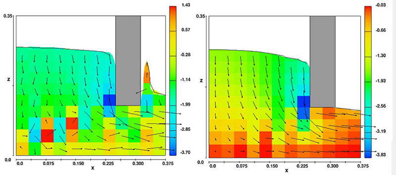
응고는 유체의 강직성 및 유동저항을 뜻한다. 이 강직성은 두 가지로 모델링 된다. 낮은 고상율에 대해 즉 Fluids Fluid 1 Solidification Model Solidified Fluid 1 Properties Coherent Solid Fraction 의 coherency 점 밑에서는 점도는 고상율의 함수이다. 간섭 고상율보다 큰 고상율에 대해서는 고상율의 함수에 비례하는 항력계수를 갖는 Darcy 형태의 항력이 이용된다. 이 항력은 모멘텀 방정식에 (bx,by,bz) 로써 추가된다- Momentum Equations 를 보라. 이 항력의 계산은 Solidification Drag Model 에서 기술된다. 항력계수는 사용자가 유동저항에 양을 조절할 수 있는 Coefficient of Solidification Drag 인자를 포함한다. 항력계수는 FLOW-3D 출력에서 기록된 속도에 상응하는 지역 상 평균 속도에 의해 곱해진다.

Fluid 1 Properties)을 지나면 항력은 무한대가 되고 계산격자 관련하여 유동이 있을 수 없다(단 예외로 Moving Solid Phase를 참조).

Note

모든 유체가 완전히 응고하면 모사를 정지시키기 위해 General Finish condition Solidified fluid fraction 를 이용한다. General Finish condition Finish fraction 은 모사를 중지하기 위한 고상율 값을 정한다.

Drag in the Mushy Zone, Mushy영역 내 항력

주조 시 mushy zone 은 액상과 고상이 혼합물로 존재하는 지역이다. 이 지역 혼합점도는 동축의 수지상 조직(과냉각된 액체 안에서 방사상으로 자라는 결정으로 된 구조) 이 액체 안에서 자유롭게 부유할 때 영향을 미친다.

일단 수지상 조직의 간섭성이 발생하여 고정된 고상 망이 형성되면 액상이 고정된 다공 수지상 구조를 통과해야 하므로 추가의 유동손실이 발생한다. 다른 방법으로는 간섭점을 지난 액/고상 혼합물은 다공물질을 통한 유동 대신에 고점도의 유체로 간주될 수 있다. 점성유체로 간주하는 접근은 예를 들면 연속 이중 롤 주조 과정같이 고상이 계속 이동 및 변형할 때 유용하다.

Solidification Drag Models in FLOW-3D, FLOW-3D 내 응고 항력모델

응고에 의한 항력계수를 정의하기 위해 사용자는 우선 열전달 및 응고모델을 활성화 해야 한다. 이들은 Model Setup Physics 탭 에서 활성화될 수 있다. 수축모델 또한 응고모델 창에서 활성화될 수 있다.

Solidification model

일단 Solidification 모델이 활성화되면 항력의 공식이 지정될 필요가 있다. Solidification대화의 밑 좌측 모퉁이에서 Porous media drag-based Viscosity-based 의 항력공식 중의 선택을 한다.

    • Viscosity-based 공식은 점성 유체로 취급하며 Viscosity 영역 내Flow model for solidified metal 입력 밑에서 지정되는 순수 고상 점성을 갖는 고상화된 유체로 간주된다. 이 접근법은 경직성의 항력모델(즉, 응고 금속이 롤러 사이로 압착될 때)을 사용할 수 없는 경우의 모사에 이용된다. 이 점성은 고상율에 따라 선형으로 변한다.고상율이0일 때 점도는 유체1의 점도이다.고상율이1이면 점도는 Solidification 패널에서 지정된 값과 같다.
    • Porous media drag-based 공식은 응고상태를 결정하기 위해 고상율을 사용한다. 고상율이 Critical Solid Fraction 이거나 초과하면 이때 항력은 무한대가 된다-즉, 액상/고상 혼합물은 고체같이 거동한다. 고상율이 Coherent Solid Fraction 보다 작으면 항력은 0이다. 이 두 값 사이에서 유동은 mushy 지역에 있고 이를 통한 유동은 마치 다공질 내에서의 유동같이 처리된다. 또한 모델은 고상율이 Coherent Solid Fraction 보다 작을 때 자동적으로 용융 금속의 점도를 조절한다. 이 상태에서 고상결정은 점도를 올리지만 결합하지는 않는다(즉, 간섭 없음). 일단 유체가 Coherent Solid Fraction 에 도달하면 항력방정식이 고려되고 점도는 간섭성에 도달하기 전의 값으로 일정하게 된다. 임계 및 간섭 고상율은 사용자가 정의하며 논문이나 책 등에서 찾을 수 있다. 이 식에서는 Coefficient of Solidification Drag 가 정의되어야 한다. 이는 Solidification 창 또는 Fluid 1 Solidification ModelSolidified Fluid 1 Properties tree Other 트리를열어 Model Setup Fluids 탭에서 될 수 있다.

How to Calculate Permeability 투과성 계산법

밑에 주어진 Darcy법칙은 수지상 구조를 위한 다공매질내의 수학적 유동기술이다.[Poi87].

(19)\mathbf{u} = - \frac{K}{\mu} \nabla P

여기서 u 는 수지상 구조 내 유동의 속도이고 ∇P 는 지역 압력구배, 그리고 K 는 mushy 구역의 특정 투수성이다. 이 방정식은 단지 유동이 거의 정상 상태이고, 관성효과가 없으며 유체의 체적율이 일정하고 균일하며 액체-액체의 상호작용 힘이 없을 때 유효하다. 투수성을 정의하는데 이용될 수 있는 대 여섯 개의 모델이 있으나 FLOW-3D 는 밑에 보여주는 Blake-Kozeny 을 이용한다. 다른 모델들은 코드와 함께 제공되는 소스코드를 사용자 사양에 맞게 수정하여 추가할 수 있다.

(20)\mathbf{u} = -C_2 \left( \frac{\lambda_1^2 (1-f_s)^3}{\mu f_s^2} \right) \left( \nabla P - \rho \mathbf{g} \right)

여기서

C2 는 전형적으로 와 같은 비틀림

fs 는 고상율이고

λ1는 유동을 위한 특정 치수

이 응용에서 수지상 가지 간격(DAS)이 이용된다.

  • 식 (11.19) 을 식(11.20) 에 적용하면 투수성을 위한 다음 식을 얻는다.

(21)K = \lambda_1^2 \frac{(1-f_s)^3}{180f_s^2}

수지상 가지 간격(DAS)에 대한 일반적인 값들은 밑에 주어져 있다.

Range of Cooling Rates in Solidification Processes
COOLING RATE, K/s PRODUCTION PROCESSES DENDRITE ARM SPACING, \mu m
10^{-4} to 10^{-2} large castings 5000 to 200
10^{-2} to 10^3 small castings, continuous castings, die castings, strip castings, coarse powder atomization 200 to 5
10^3 to 10^9 fine powder atomization, melt spinning, spray deposition, electron beam or laser surface melting 5 to 0.05

Range of cooling rates in solidification processes [CF85]

How FLOW-3D Defines the Coefficient of Solidification Drag FLOW-3D 가 응고 항력계수를 결정하는법

FLOW-3D 는 액고상 변화를 모델링하기 위해 다공매질항력을 이용한다. 항력은 고상율의 함수이다. 사용자에게 두 수축모델이 이용 가능하다; 급속 수축 모델 과 완전 유동모델. 급속 수축 모델은 상변화와 연관된 체적변화를 고려하지 않으며 유체는 정지해 있다고 가정한다. 완전 유동모델은 상변화가 관련된 체적변화를 고려한다. 항력은 투수성에 역으로 비례하므로 다음과 같이 표현될 수 있다.

(22)K = \frac{\mu}{\rho F_d}

여기서, Fd FLOW-3D 에서 사용된 항력계수이다. 이 항력계수는 지역 속도에 의해 곱해지고 모멘텀 방정식의 오른쪽에서 차감된다 (Momentum Equations 참조). 식 (11.22) 를 재정리하고 식 (11.21) 로부터의 투수성에 치환하면 다음을 얻는다.

  • The Coefficient of Solidification Drag: \text{TSDRG}=\frac{180 \mu}{\lambda_1^2\rho },
  • The drag force: F_d = \mbox{TSDRG} \frac{ f_s^2}{(1-f_s)^3}.

Macro-Segregation during Alloy Solidification 합금응고시 거시적 편절

편절 모델은 대류와 확산에 의한 용질 이동에 따른 이원합금 요소에서의 변화를 모델링 하도록 되어 있다. 이 모델링은 Physics → Solidification 로 부터 될 수 있다.

Solidification

Activate binary alloy segregation model 을 체크하고 편절 모델을 활성화한다.

여러 온도에서 평형에 있는2원합금 요소농도를 정의하는 상태도는 직선의 고상선 및 액상선을 가진다고 가정된다. 상태도는 입력데이터에 의해 구성되고 전처리 그림파일 prpplt 에 포함된다. Analyze Existing 에서 이용 가능하다

Macro-Segregation Model (under Fluids Fluid 1 Solidification Model)에 관련된 일부 유체물성 트리가 밑에 보여진다. 상태도는 Reference Solute Concentration 에서의 the Solidus Liquidus Temperatures 값들에 의해 정의된다. 추가로 Concentration Variables 밑의 Partition coefficient 도 정의되어야 한다. 그렇지 않으면 Pure Solvent Melting Temperature 가 정의될 수 있다. Partition coefficient Pure Solvent Melting Temperature 둘 다가 지정되면 용매 용융 온도는 상태도로부터 재 정의된다.

Macro segregation fluid properties

Eutectic Temperature 또는 Eutectic Concentration 는 융해작용을 정의하기 위해 지정될 수 있다. 또 이 두 변수가 다 지정되면 Eutectic Concentration 은 상태도에서 재 정의된다.

Diffusion Coefficients 는 고상과 액상 사이의 용질의 확산계수 비율을 정의한다. 액체 내의 용질의 분자 확산계수는 Physics Solidification 에서 specifying Solute diffusion coefficient 를 지정함으로써 정해진다. RMSEG 는 용질의 난류 확산계수 승수를 정의한다; 이는 입력파일에서 직접 지정된다.

Density evaluation

용질 재 분배에 의한 농도변화가 중요하면 Physics Density evaluation Density evaluated as a function of other quantities를 정하고 용질농도의 선형함수로써 금속농도를 정의하기 위해 Fluids Segregation model 밑의 Solutal Expansion Coefficient 를 용질 확장계수로 지정한다. 이 경우 Reference Solute Concentration 이 기준농도로 사용될 것이다. 추가로 Fluids Fluid 1 Density Properties Volumetric Thermal Expansion 은 액체 내 열부력 효과를 참작하기 위해 지정될 수 있다(또한 Buoyant Flow참조).

초기 용질농도는 Meshing & Geometry Initial Global Uniform alloy solute concentration 에서 지정될 수 있다. 불 균일한 초기 분포는 Alloy solute concentration 밑의 초기유체 구역 안에서 정의될 수 있다. 추가로 농도는 Initial Conditions: Region Values 에서 기술된 바와 같이 2차함수를 사용하는 부분을 편집하여 공간상의2차함수로 변화할 수 있다. 압력과속도 경계에서 용질 경계조건을 정하기 위해 Boundaries Boundary face Solute concentration 를 이용한다.

액상 및 고상 구성은 후처리에서 데이터 변환을 이용하여 그려질 수 있다. 용융 응고금속은 금속 내 용융의 질량 분율을 저장하는 SLDEUT 를 그림으로써 가시화될 수 있다.

액상 내 열구배가 크면 Physics Heat Transfer Second order monotonicity preserving 를 지정함으로써 더 나은 정확성을 위해 고차원 이류법을 사용한다.

Heat Transfer

mushy 지역에서의 유동손실은 수지상 가지 간격(DAS)의 함수인 Fluids Fluid 1 Solidification Model Solidified Fluid 1 Properties Coefficient of Solidification Drag 에 의해 조절된다. 후자는 이 모델에 의해 계산되지 않으므로 사용자는 Coefficient of Solidification Drag 를 지정해야 한다

Note

  • 표준 응고모델 과는 달리 상태도상의 용융점을 지나 고상선을 외삽하여 정의되므로 여기서 응고선의 값은 음수일 수 있다.

Microporosity Formation 미세다공형성

Solidification

미세다공모델은 단지 응고(Solidification참조)를 모델링할 때 사용될 수 있고 Physics Solidification Activate micro-porosity model 에서 활성화된다. 필요한 입력은 Fluids Densities Fluid 1 and Fluids Solidification Properties Solidified Fluid 1 Properties Density 에서 정의되는 액체와 고상 유체밀도이며 고상유체밀도는 액체밀도보다 크다. 또한 Fluids Fluid 1 Solidification Model Solidified Fluid 1 Properties 안에 있는 Critical Solid Fraction 은 1.0보다작게 설정되어야 한다.

Square of the speed of sound at critical solid fraction 값이 정의될 수 있다. 이는 수축에 의해 mushy 지역에서 전개되는 커다란 음압에서의 응고유체의 압축성을 기술한다. Critical pressure at which gas pores can form 값은 모델이 Initial tab 탭에서 또는 재 시작 데이터에서 정의되는 유체내의 초기 압력과 결합되도록 한다.

Intensification pressure 또한 다공 생성을 지연시키기 위해 응고 시 shot sleeve plunger 에 의해 형성되는 추가압력을 고려하기 위한 고압 주조모사를 위해 정의될 수 있다. Intensification pressure 가 클수록 더 적은 양의 다공이 주조 시 응고 과정에서 발생할 것이다.

미세 다공 모델은 응고 모델의 활성화 이외의 어떤 다른 설정을 필요로 하지 않는다. 이는 완전 유동방정식이나 속도장이 0인 경우, 즉 순수한 열 문제에서도 함께 사용될 수 있다.

이 모델은 후처리 과정의 공간 및 이력에서 사용 가능한 Percent micro-porosity 라고 불리는 추가 출력 양을 생성한다.

Note

A Flow Science technical note on modeling micro-porosity (TN66) can be found at http://users.flow3d.com/technical-notes/.

Moving Solid Phase  이동고상

MAIN VARIABLES: OBS: IFOB, UTOBS, VTOBS, WTOBS

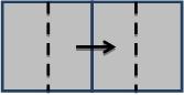
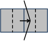
이동고상 선택은 연속주조 모델링을 가능하게 한다. Continuous Casting Phantom 요소는 응고된 이동 유체가 있는 지역에서 정의된다. 이는 지정된 영역을 차지하지만 정의에만 존재하므로 환영요소라고 한다. 이는 실제로 면적이나 체적을 차지하지 않으므로 체적이 없고 결과에서도 고체요소로 보이지 않는다. 이는 Meshing & Geometry Geometry Component Component Type 옆 펼쳐지는 메뉴에서 정의된다.

Moving solid phase selection

다른 방법으로는 입력파일(prepin.*)에서 IFOB(N) 변수가 4로 지정되고 N 은 요소 번호이다. 이 파일은 File Edit Simulation…. 을 선택하여 이용될 수 있다. 또한 입력파일에서 시간의 함수(TOBS(t) 에 의해 지정되는)일 수 있는 가상 요소의 속도성분 UTOBS(t,N), VTOBS(t,N) 그리고 WTOBS(t,N) 이 지정된다.

Fluids Fluid 1 Solidification Properties Solidified Fluid 1 Properties Coherent Solid Fraction 에 의해 정의된 간섭 고상율 보다 큰 고상율에 대해서는 Darcy 형태의 항력 이 유체를 가상 요소의 속도로 움직이게 하는데 사용된다. 고상율이 Fluids Fluid 1 Solidification Properties Solidified Fluid 1 Properties Critical Solid Fraction 에서 지정된 경직점을 능가하게 되면 가상 요소의 속도를 따라 움직일 것이다.

Note

  • 가상 요소는 요소 그림에 안 나타나나 Component number 를 그릴 때는 보여진다.가상 요소는 균일속도가 요소의 전체에 적용되므로 평평해야 한다.

Solidification Shrinkage 응고수축

체적 수축은 소재가 응고하고 응고소재의 밀도가 액체소재의 밀도보다 클 때 나타난다(즉, Fluids Fluid 1 Solidification Model Solidified Fluid 1 Properties Density > Fluids Fluid 1 Density Properties Density). 수축모델은 그러므로 Solidification 모델이 활성화되어야 하고 고상/액상의 두 밀도가 정의되어야 한다. 수축은 단지 1유체의 뚜렷한 경계면 문제에서만 모델링 될 수 있다.

두 가지 수축모델이 있다. Shrinkage model with flow effects 를 선택하면 완전 열 유체방정식을 해석한다(이론 매뉴얼의Solidification Shrinkage and Porosity Models 참조). 그러나 이 모델은 특히 장시간의 응고가 고려되면 컴퓨터 계산시간이 많이 소요된다. 다른 방법으로 사용자 Interface 에 Shrinkage model 이라고 불리는 단순모델이 있다.

Activate simplified shrinkage model

이 모델은 단지 열전달 방정식의 해석에 의존하며 특히 내재적 열전달 모델 (Numerics Explicit/implicit options Heat transfer Implicit Thermal solution 참조)과 사용시에 빨리 해석할 수 있다. 액체 체적 내로의 유동 통로가 없을 때 내부공동이 발생한다.

이 두 모델에서 유입은 mushy 지역 유동에 대한 항력계수를 계산함으로써 정의된다. 격자 내 모든 점에서의 항력함수는 상수승수 Fluids Solidification properties Other Coefficient of Solidification Drag (Solidification Drag Model 참조)를 가지는 지역 고상율의 함수로 계산된다. 항력함수의 역의 값은 공간 그림에서 가시화 될 수 있다: 이 그림을 위한 변수이름은 ‘drag coefficient’ 이다.

Mushy 지역에서의 커다란 유동 손실에 따른 부분적 유입이 Shrinkage model with flow effects 에서 발생할 수 있지만 단순화된 Shrinkage model 은 완전 유입이 아니면 유입이 없게 된다. 후자는 유입 통로를 따라 지역 고상율이 Fluids Fluid 1 Solidification Model Solidified Fluid 1 Properties Critical Solid Fraction (디폴트는1.0)에서 정의된 임계값보다 커질 때 발생한다. 추가로 고립된 액체 내의 금속의 고상율이 Coherent Solid Fraction 에 도달할 때까지 단순모델에서의 유입은 고립부 상부로부터 발생한다. 그 후로는 유입이 고립부의 가장 뜨거운 부분에서부터 발생한다.

모든 유체가 완전히 응고되면 모사가 정지하도록 General Additional finish condition Solidified fluid fraction 를 사용한다. 변수 Finish fraction 는 유체가 지정된 고상율에 도달할 때 모사가 정지하도록 하는데 사용될 수 있다.

Solid fraction finish condition

Note

이송 방향을 결정하기 위해 단순 수축 모델에서 중력이 필요하며 좌표축 중 하나를 따라야합니다. 둘 이상의 중력 구성 요소가 0이 아닌 경우, 가장 큰 중력 구성 요소가 공급 방향을 결정하는 데 사용됩니다.

Salt dissolution model [소금 용해 모델]

Introduction
Dissolution of salt in liquid is of interest in several applications – from solution mining to food processing to medical applications. This article describes a new model in FLOW-3D1 version 10.0 for dissolving salt in fluids and tracking the solute in the brine.
The dissolution of salt increases the density of the fluid and thus may affect the flow. In addition, as salt is dissolved, the flow domain increases. It is of interest, therefore, to predict these changes in the flow as well as the transport of the dissolved salt in the fluid.
The model accounts for the basic physical phenomena, such as mass transfer at the interface between salt and fluid, the change of volume and shape of the solid salt, diffusion and convection of dissolved salt in fluid and, finally, the change in fluid density, viscosity and surface tension coefficient.

Turbulent Flow Over a Backward-Facing Step Using the RNG Model

Abstract
Turbulent flow over a backward-facing step is one of the classical tests to validate turbulence models in CFD. In the present work, steady-state turbulent flow over a backward-facing step was simulated using FLOW-3D1 with the Renormalization-group (RNG) k-ε model to account for turbulent viscosity. The Reynolds number was computed using the step height h and the inlet free-stream velocity. The test case was run for two different Reynolds numbers: Reh=5100 and Reh=44,000.

The numerical predictions were compared with the experimental results with the same flow configuration. Streamwise velocity profiles at different locations in the flow direction were in good agreement both qualitatively and quantitatively with the experimental results.

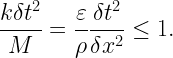
One of the main objectives of this work is to study the sensitivity of the results to the turbulent mixing length parameter tlen in the RNG model. The steady-state velocity was used to compute the reattachment length behind the step for different values of tlen and compared with experimental data. A grid refinement study was performed to find the least mesh resolution needed to capture the essential flow physics of the problem.

Simulating the Residue left by Evaporating Drops

Background
The “coffee ring” effect is the name given to a well known observation where the evaporative drying of a drop of coffee leaves behind a ring of dark material at the edge of the original drop. On first thought one would expect that the coffee particles, which are uniformly distributed in the drop, would simply be deposited uniformly over the area wetted by the drop. It has only been in recent years that researchers have uncovered the mechanisms that produce the ring effect (Deegan, R.D., et al).
As currently understood, the edges of drops can become pinned because of roughness or chemical elements on the surface on which they lie. Heat transfer to the drops from the substrate or the air induces evaporation, which is usually greater near the drop edge. Surface tension forces then adjust the curvature of the remaining liquid consistent with the pinned edge, which results in a net flow of liquid toward the edge. This flow replenishes the evaporative loss but also moves solute to the edge where it is concentrated by evaporation. Eventually, this mechanism builds up a ring deposit of solute at the original edge of the drop.
The residue from dried drops has implications for many useful applications, including general coating processes, formation of pixel arrays of organic materials for video displays and for a variety of micro-electro-mechanical (MEMS) devices.
Because many factors control the distribution of dried residue it is desirable to have some means to model the fluid dynamics of the process to aid engineers in making the best choices for each specific application. Such a capability has been incorporated into FLOW-3D1 making it possible to computationally investigate the influence of such parameters as the initial solute concentration, fluid viscosity, volatility of the solvent, evaporation rate, surface tension and initial shape of the drop.
This technical note presents a brief description of the residue formation model and illustrates it with several computations of an evaporating drop subject to different physical conditions.

Modeling of Electroosmosis without Resolving Physics inside the Electric Double Layer

A model for electroosmosis has been developed and released in version 8.2 of FLOW-3Dr. It is a general model in which the zeta potential distribution is solved through the electric double layer (EDL). When the EDL thickness (¸D) is very small, such as ¸D < 0:1¹m or in nanoscale, it is very computationally expensive to resolve the physics inside the EDL. In this note, we describe a simple model that has been developed to simulate electroosmosis without resolving the EDL.

That is, the zeta potential distribution is not solved, instead, a zeta potential on the obstacle surface is used as a boundary condition to calculate a slip velocity. This velocity is imposed on the obstacle surface if a zeta potential exists around that obstacle. It is de¯ned by ³²Ex ¹ and called the Helmholtz-Smoluchowski velocity with ³, Ex, ¹ representing zeta potential, electric ¯eld intensity in x-direction, ² permittivity, and liquid viscosity respectively.

However, if the EDL thickness is large compared to the problem geometry such as channel width, the simpli¯ed model is not accurate, and the original model is recommended. The new model has been validated against the corresponding analytical solution in a channel °ow and its application to complex microchannel °ow is demonstrated. The new simpli¯ed model will be incorporated in a future version of FLOW-3D

Sediment Scour [침전 / 세굴(쇄굴)]

Introduction
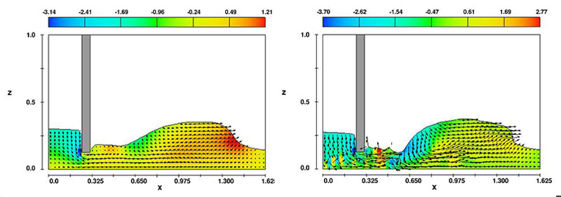
The sediment scour model predicts the behavior of packed and suspended sediment within the three-dimensional flow capabilities of FLOW-3D®. Potential applications include erosion around bridge piers, weirs, dams and underwater pipelines, and removal and drifting of sand or snow over terrain. The model consists of two basic components: drifting and lifting. Drifting acts on sediment that is suspended in the flow; gravity (along with other body forces) causes the settling of the sediment. This model is based on the drift-flux model already incorporated into FLOW-3D®. Lifting takes place only at the interface between the packed sediment and fluid and occurs where the local shear stress imposed by the liquid on the bed interface exceeds a critical value. The amount of lifting is proportional to the shear stress. In conjunction with the drifting and lifting models, a drag model is used to mimic the solid-like behavior of the sediment in regions where its concentration exceeds a cohesive solid fraction. The viscosity and density are functions of the sediment concentration; they are calculated as a function of the sediment concentration.

Coating Bibliography

아래는 코팅 참고 문헌의 기술 문서 모음입니다. 
이 모든 논문은 FLOW-3D  결과를 포함하고 있습니다. FLOW-3D를 사용하여 코팅 공정을 성공적으로 시뮬레이션  하는 방법에 대해 자세히 알아보십시오.

Coating Bibliography

2024년 11월 20일 Update

98-24 Fabiano I. Indicatti, Bo Cheng, Michael Rädler, Elisabeth Stammen, Klaus Dilger, Experimental and numerical investigation of the squeegee process during stencil printing of thick adhesive sealings, The Journal of Adhesion, 2024. doi.org/10.1080/00218464.2024.2356105

130-22   Md Didarul Islam, Himendra Perera, Benjamin Black, Matthew Phillips, Muh-Jang Chen, Greyson Hodges, Allyce Jackman, Yuxuan Liu, Chang-Jin Kim, Mohammed Zikry, Saad Khan, Yong Zhu, Mark Pankow, Jong Eun Ryu, Template-free scalable fabrication of linearly periodic microstructures by controlling ribbing defects phenomenon in forward roll coating for multifunctional applications, Advanced Materials Interfaces, 9.27; 2201237, 2022. doi.org/10.1002/admi.202201237

03-21   Delong Jia, Peng Yi, Yancong Liu, Jiawei Sun, Shengbo Yue, Qi Zhao, Effect of laser­ textured groove wall interface on molybdenum coating diffusion and metallurgical bonding, Surface and Coatings Technology, 405; 126561, 2021. doi.org/10.1016/j.surfcoat.2020.126561

50-19     Peng Yi, Delong Jia, Xianghua Zhan, Pengun Xu, and Javad Mostaghimi, Coating solidification mechanism during plasma-sprayed filling the laser textured grooves, International Journal of Heat and Mass Transfer, Vol. 142, 2019. doi:10.1016/j.ijheatmasstransfer.2019.118451

01-19   Jelena Dinic and Vivek Sharma, Computational analysis of self-similar capillary-driven thinning and pinch-off dynamics during dripping using the volume-of-fluid method, Physics of Fluids, Vol. 31, 2019. doi: 10.1063/1.5061715

85-18   Zia Jang, Oliver Litfin and Antonio Delgado, A semi-analytical approach for prediction of volume flow rate in nip-fed reverse roll coating process, Proceedings in Applied Mathematics and Mechanics, Vol. 18, no. 1, Special Issue: 89th Annual Meeting of the International Association of Applied Mathematics and Mechanics, 2018. doi: 10.1002/pamm.201800317

80-14   Hiroaki Koyama, Kazuhiro Fukada, Yoshitaka Murakami, Satoshi Inoue, and Tatsuya Shimoda, Investigation of Roll-to-Sheet Imprinting for the Fabrication of Thin-film Transistor Electrodes, IEICE TRAN, ELECTRON, VOL.E97-C, NO.11, November 2014

46-14   Isabell Vogeler, Andreas Olbers, Bettina Willinger and Antonio Delgado, Numerical investigation of the onset of air entrainment in forward roll coating, 17th International Coating Science and Technology Symposium September 7-10, 2014 San Diego, CA, USA

17-12  Chi-Feng Lin, Bo-Kai Wang, Carlos Tiu and Ta-Jo Liu, On the Pinning of Downstream Meniscus for Slot Die Coating, Advances in Polymer Technology, Vol. 00, No. 0, 1-9 (2012) © 2012 Wiley Periodicals, Inc. Available online at Wiley.

01-11  Reid Chesterfield, Andrew Johnson, Charlie Lang, Matthew Stainer, and Jonathan Ziebarth, Solution-Coating Technology for AMOLED Displays, Information Display Magazine, 1/11 0362-0972/01/2011-024 © SID 2011.

61-09 Yi-Rong Chang, Chi-Feng Lin and Ta-Jo Liu, Start-up of slot die coating, Polymer Engineering and Science, Vol. 49, pp. 1158-1167, 2009. doi:10.1002/pen.21360

26-06  James M. Brethour, 3-D transient simulation of viscoelastic coating flows, 13th International Coating Science and Technology Symposium, September 2006, Denver, Colorado

19-06  Ivosevic, M., Cairncross, R. A., and Knight, R., 3D Predictions of Thermally Sprayed Polymer Splats Modeling Particle Acceleration, Heating and Deformation on Impact with a Flat Substrate, Int. J. of Heat and Mass Transfer, 49, pp. 3285 – 3297, 2006

9-06  M. Ivosevic, R. A. Cairncross, R. Knight, T. E. Twardowski, V. Gupta, Drexel University, Philadelphia, PA; J. A. Baldoni, Duke University, Durham, NC, Effect of Substrate Roughness on Splatting Behavior of HVOF Sprayed Polymer Particles Modeling and Experiments, International Thermal Spray Conference, Seattle, WA, May 2006.

26-05  Ivosevic, M., Cairncross, R. A., Knight, R., Impact Modeling of Thermally Sprayed Polymer Particles, Proc. International Thermal Spray Conference [ITSC-2005], Eds., DVS/IIW/ASM-TSS, Basel, Switzerland, May 2005.

11-05  Brethour, J., Simulation of Viscoelastic Coating Flows with a Volume-of-fluid Technique, in Proceedings of the 6th European Coating Symposium, Bradford, UK, 2005

1-05 C.W. Hirt, Electro-Hydrodynamics of Semi-Conductive Fluids: With Application to Electro-Spraying, Flow Science Technical Note #70, FSI-05-TN70

38-04 K.H. Ho and Y.Y. Zhao, Modelling thermal development of liquid metal flow on rotating disc in centrifugal atomisation, Materials Science and Engineering, A365, pp. 336-340, 2004. doi:10.1016/j.msea.2003.09.044

30-04  M. Ivosevic, R.A. Cairncross, and R. Knight, Impact Modeling of HVOF Sprayed Polymer Particles, Presented at the 12th International Coating Science and Technology Symposium, Rochester, New York, September 23-25, 2004

29-04  J.M. Brethour and C.W. Hirt, Stains Arising from Dried Liquid Drops, Presented at the 12th International Coating Science and Technology Symposium, Rochester, New York, September 23-25, 2004

20-03  James Brethour, Filling and Emptying of Gravure Cells–A CFD Analysis, Convertech Pacific October 2002, Vol. 10, No 4, p 34-37

4-03   M. Toivakka, Numerical Investigation of Droplet Impact Spreading in Spray Coating of Paper, In Proceedings of 2003 TAPPI 8th Advanced Coating Fundamentals Symposium, TAPPI Press, Atlanta, 2003

28-02  J.M. Brethour and H. Benkreira, Filling and Emptying of Gravure Cells—Experiment and CFD Comparison, 11th International Coating Science and Technology Symposium, September 23-25, 2002, Minneapolis, Minnesota

22-02  Hirt, C.W., and Brethour, J.M., Contact Line on Rough Surfaces with Application to Air Entrainment, Presented at the 11th International Coating Science and Technology Symposium, September 23-25, 2002, Minneapolis, Minnesota. Unpublished.

17-01  J. M. Brethour, C. W. Hirt, Moving Contact Lines on Rough Surfaces, 4th European Coating Symposium, 2001, Belgium

16-01  J. M. Brethour, Filling and Emptying of Gravure Cells–-A CFD Analysis, proceedings of the 4th European Coating Symposium 2001, October 1-4, 2001, Brussels, Belgium

26-00 Ronald H. Miller and Gary S. Strumolo, A Self-Consistent Transient Paint Simulation, Proceedings of IMEC2000: 2000 ASME International Mechanical Engineering Congress and Exposition, November 2000, Orlando, Florida

6-99  C. W. Hirt, Direct Computation of Dynamic Contact Angles and Contact Lines, ECC99 Coating Conference, Erlangen, Germany (FSI-99-00-2), Sept. 1999

7-98 J. E. Richardson and Y. Becker, Three-Dimensional Simulation of Slot Coating Edge Effects, Flow Science Inc, and Polaroid Corporation, presented at the 9th International Coating Science and Technology Symposium, Newark, DE, May 18-20, 1998

6-98  C. W. Hirt and E. Choinski, Simulation of the Wet-Start Process in Slot Coating, Flow Science Inc, and Polaroid Corporation, presented at the 9th International Coating Science and Technology Symposium, Newark, DE, May 18-20, 1998

3-97  C. W. Hirt and J. E. Richardson of Flow Science Inc, and K.S. Chen, Sandia National Laboratory, Simulation of Transient and Three-Dimensional Coating Flows Using a Volume-of-Fluid Technique, presented at the 50th Annual Conference of the Society for Imaging and Science Technology, Boston, MA 18-23 May 1997

2-96 C. W. Hirt, K. S. Chen, Simulation of Slide-Coating Flows Using a Fixed Grid and a Volume-of-Fluid Front-Tracking Technique, presented a the 8th International Coating Process Science & Technology Symposium, February 25-29, 1996, New Orleans, LA

General Applications Bibliography

다음은 일반 응용 분야의 기술 문서 모음입니다.
이 모든 논문은 FLOW-3D  결과를 포함하고 있습니다. 복잡한 다중 물리와 관련된 문제를 성공적으로 시뮬레이션하기 위해 FLOW-3D를 사용 하는 방법에 대해 자세히 알아보십시오.

Below is a collection of technical papers in our General Applications Bibliography. All of these papers feature FLOW-3D results. Learn more about how FLOW-3D can be used to successfully simulate problems that involve complex multiphysics.

2024년 8월 12일 Upate

204-23   Togo Shinonaga, Hibiki Tajima, Yasuhiro Okamoto, Akira Okada, Application of large-area electron beam irradiation to micro-edge filleting, Journal of Manufacturing Processes, 107; pp. 65-73, 2023. doi.org/10.1016/j.jmapro.2023.10.039

167-23   Xiaoyong Cheng, Zhixian Cao, Ji Li, Alistair Borthwick, A numerical study of the settling of non-spherical particles in quiescent water, Physics of Fluids, 35.9; 2023. doi.org/10.1063/5.0165555

109-23 Dileep Karnam, Yu-Lung Lo, Chia-Hua Yang, Simulation study and parameter optimization of laser TSV using artificial neural networks, Journal of Materials Research and Technology, 25; pp. 3712-3727, 2023. doi.org/10.1016/j.jmrt.2023.06.199

66-23   Erik Holmen Olofsson, Michael Roland, Jon Spangenberg, Ninna Halberg Jokil, Jesper Henri Hattel, A CFD model with free surface tracking: predicting fill level and residence time in a starve-fed single-screw extruder, The International Journal of Advanced Manufacturing Technology, 126; pp. 3579-3591, 2023. doi.org/10.1007/s00170-023-11329-w

20-23   Giampiero Sciortino, Valentina Lombardi, Pietro Prestininzi, Modelling of cantilever-based flow energy harvesters featuring C-shaped vibration inducers: The role of the fluid/beam interaction, Applied Sciences, 13.1; 416, 2023. doi.org/10.3390/app13010416

134-22   Guozheng Ma, Shuying Chen, Haidou Wang, Impact spread behavior of flying droplets and properties of splats, Micro Process and Quality Control of Plasma Spraying, pp. 87-202, 2022. doi.org/10.1007/978-981-19-2742-3_3

111-22   Chia-Lin Chiu, Chia-Ming Fan, Chia-Ren Chu, Numerical analysis of two spheres falling side by side, Physics of Fluids, 34; 072112, 2022. doi.org/10.1063/5.0096534

58-21   Ruizhe Liu, Haidong Zhao, Experimental study and numerical simulation of infiltration of AlSi12 alloys into Si porous preforms with micro-computed tomography inspection characteristics, Journal of the Ceramic Society of Japan, 129.6; pp. 315-322, 2021. doi.org/10.2109/jcersj2.21018

56-20   Nils Steinau, CFD modeling of ascending Strombolian gas slugs through a constricted volcanic conduit considering a non-linear rheology, Thesis, Universität Hamburg, Hamburg, Germany, 2020.

30-20   Bita Bayatsarmadi, Mike Horne, Theo Rodopoulos and Dayalan Gunasegaram, Intensifying diffusion-limited reactions by using static mixer electrodes in a novel electrochemical flow cell, Journal of The Electrochemical Society, 167.6, 2020. doi.org/10.1149/1945-7111/ab7e8f

75-19   Raphaël Comminal, Marcin Piotr Serdeczny, Navid Ranjbar, Mehdi Mehrali, David Bue Pedersen, Henrik Stang, Jon Spangenberg, Modelling of material deposition in big area additive manufacturing and 3D concrete printing, Proceedings, Advancing Precision in Additive Manufacturing, Nantes, France, September 16-18, 2019.

35-19     Sung-Won Ha, Tae-Won Kim, Joo-Hwan Choi, and Young-Jin Park, Study for flow phenomenon in the circulation water pump chamber using the Flow-3D model, Journal of the Korea Academia-Industrial Cooperation Society, Vol. 20, No. 4, pp. 580-589, 2019. doi: 10.5762/KAIS.2019.20.4.580

27-19     Rolands Cepuritis, Elisabeth L. Skare, Evgeny Ramenskiy, Ernst Mørtsell, Sverre Smeplass, Shizhao Li, Stefan Jacobsen, and Jon Spangeberg, Analysing limitations of the FlowCyl as a one-point viscometer test for cement paste, Construction and Building Materials, Vol. 218, pp. 333-340, 2019. doi: 10.1016.j.conbuildmat.2019.05.127

26-19     Shanshan Hu, Lunliang Duan, Qianbing Wan, and Jian Wang, Evaluation of needle movement effect on root canal irrigation using a computational fluid dynamics model, BioMedical Engineering OnLine, Vol. 18, No. 52, 2019. doi: 10.1186/s12938-019-0679-5

83-18   Elisabeth Leite Skare, Stefan Jacobsen, Rolands Cepuritis, Sverre Smeplass and Jon Spangenberg, Decreasing the magnitude of shear rates in the FlowCyl, Proceedings of the 12th fib International PhD Symposium in Civil Engineering, Prague, Czech Republic, August 29-31, 2018.

71-18   Marc Bascompta, Jordi Vives, Lluís Sanmiqeul and José Juan de Felipe, CFD friction factors verification in an underground mine, Proceedings of the 4th World Congress on Mechanical, Chemical, and Material Engineering, August 16 – 18, 2018, Madrid, Spain, Paper No. MMME 105, 2018. doi.org/10.11159/mmme18.105

56-18   J. Spangenberg, A. Uzala, M.W. Nielsen and J.H. Hattel, A robustness analysis of the bonding process of joints in wind turbine blades, International Journal of Adhesion and Adhesives, vol. 85, pp. 281-285, 2018. doi.org/10.1016/j.ijadhadh.2018.06.009

21-18   Zhang Weikang and Gong Hongwei, Numerical Simulation Study on Characteristics of Airtight Water Film with Flow Deflectors, IOP Conference Series: Earth and Environmental Science vol. 153, no. 3, pp. 032025, 2018. doi.org/10.1088/1755-1315/153/3/032025

59-17  Han Eol Park and In Cheol Bang, Design study on mixing performance of rotational vanes in subchannel with fuel rod bundles, Transactions of the Korean Nuclear Society Autumn Meeting, Gyeongju, Korea, October 26-27, 2017.

58-17  Jian Zhou, Claudia Cenedese, Tim Williams and Megan Ball, On the propagation of gravity currents over and through a submerged array of circular cylinders, Journal of Fluid Mechanics, Vol. 831, pp. 394-417, 2017. doi.org/10.1017/jfm.2017.604

24-17   Zhiyuan Ge, Wojciech Nemec, Rob L. Gawthorpe, Atle Rotevatn and Ernst W.M. Hansen, Response of unconfined turbidity current to relay-ramp topography: insights from process-based numerical modelling, doi: 10.1111/bre.12255 This article is protected by copyright. All rights reserved.

06-17   Masoud Hosseinpoor, Kamal H. Khayat, Ammar Yahia, Numerical simulation of self-consolidating concrete flow as a heterogeneous material in L-Box set-up: coupled effect of reinforcing bars and aggregate content on flow characteristics, A. Mater Struct (2017) 50: 163. doi:10.1617/s11527-017-1032-8

94-16   Mehran Seyed Ahmadi, Markus Bussmann and Stavros A. Argyropoulos, Mass transfer correlations for dissolution of cylindrical additions in liquid metals with gas agitation, International Journal of Heat and Mass Transfer, Volume 97, June 2016, Pages 767-778

83-16   Masoud Hosseinpoor, Numerical simulation of fresh SCC flow in wall and beam elements using flow dynamics models, Ph.D. Thesis: University of Sherbrooke, September 2016.

51-16   Aditi Verma, Application of computational transport analysis – Oil spill dynamics, Master Thesis: State University of New York at Buffalo, 2016, 56 pages; 1012775

37-16   Hannah Dietterich, Einat Lev, and Jiangzhi Chen, Benchmarking computational fluid dynamics models for lava flow simulation, Geophysical Research Abstracts, Vol. 18, EGU2016-2202, 2016, EGU General Assembly 2016, © Author(s) 2016. CC Attribution 3.0 License.

 19-16   A.J. Vellinga, M.J.B. Cartigny, E.W.M. Hansen, P.J. Tallinga, M.A. Clare, E.J. Sumner and J.T. Eggenhuisen, Process-based Modelling of Turbidity Currents – From Computational Fluid-dynamics to Depositional Signature, Second Conference on Forward Modelling of Sedimentary Systems, 25 April 2016, DOI: 10.3997/2214-4609.201600374

106-15    Hidetaka Oguma, Koji Tsukimoto, Saneyuki Goya, Yoshifumi Okajima, Kouichi Ishizaka, and Eisaku Ito, Development of Advanced Materials and Manufacturing Technologies for High-efficiency Gas Turbines, Mitsubishi Heavy Industries Technical Review Vol. 52 No. 4, December 2015

93-15   James M. Brethour, Modelling of Cavitation within Highly Transient Flows with the Volume of Fluid Method, 1st Pan-American Congress on Computational Mechanics, April 27-29, 2015

90-15   Troy Shinbrot, Matthew Rutala, Andrea Montessori, Pietro Prestininzi and Sauro Succi, Paradoxical ratcheting in cornstarch, Phys. Fluids 27, 103101 (2015); http://dx.doi.org/10.1063/1.4934709

84-15   Nicolas Roussel, Annika Gram, Massimiliano Cremonesi, Liberato Ferrara, Knut Krenzer, Viktor Mechtcherine, Sergiy Shyshko, Jan Skocec, Jon Spangenberg, Oldrich Svec, Lars Nyholm Thrane and Ksenija Vasilic, Numerical simulations of concrete flow: A benchmark comparison, Cem. Concr. Res. (2015), http://dx.doi.org/10.1016/j.cemconres.2015.09.022

02-15   David Souders, FLOW-3D Version 11 Enhances CFD Simulation, Desktop Engineering, January 2015

125-14   Herbert Obame Mve, Romuald Rullière, Rémi Goulet and Phillippe Haberschill, Numerical Analysis of Heat Transfer of a Flow Confined by Wire Screen in Lithium Bromide Absorption Process, Defect and Diffusion Forum, ISSN: 1662-9507, Vol. 348, pp 40-50, doi:10.4028/www.scientific.net/DDF.348.40, © 2014 Trans Tech Publications, Switzerland

55-14   Agni Arumugam Selvi, Effect of Linear Direction Oscillation on Grain Refinement, Master’s Thesis: The Ohio State University, Graduate Program in Mechanical Engineering, Copyright by Agni Arumugam Selvi, 2014

99-13   R. C. Givler and M. J. Martinez, Computational Model of Miniature Pulsating Heat Pipes, SANDIA REPORT, SAND2012-4750, Unlimited Release, Printed January 2013.

82-13    Shizhao Li, Jon Spangenberg, Jesper Hattel, A CFD Approach for Prediction of Unintended Porosities in Aluminum Syntactic Foam A Preliminary Study, 8th International Conference on Porous Metals and Metallic Foams (METFOAM 2013), Raleigh, NC, June 2013

81-13   S. Li, J. Spangenberg, J. H. Hattel, A CFD Model for Prediction of Unintended Porosities in Metal Matrix Composites A Preliminary Study, 19th International Conference on Composite Materials (ICCM 2013), Montreal, Canada, July 2013

78-13   Haitham A. Hussein, Rozi Abdullah, Sobri, Harun and Mohammed Abdulkhaleq, Numerical Model of Baffle Location Effect on Flow Pattern in Oil and Water Gravity Separator Tanks, World Applied Sciences Journal 26 (10): 1351-1356, 2013, ISSN 1818-4952, DOI: 10.5829/idosi.wasj.2013.26.10.1239, © IDOSI Publications, 2013

74-13  Laetitia Martinie, Jean-Francois Lataste, and Nicolas Roussel, Fiber orientation during casting of UHPFRC: electrical resistivity measurements, image analysis and numerical simulations, Materials and Structures, DOI 10.1617/s11527-013-0205-3, November 2013. Available for purchase online at SpringerLink.

67-13 Stefan Jacobsen, Rolands Cepuritis, Ya Peng, Mette R. Geiker, and Jon Spangenberg, Visualizing and simulating flow conditions in concrete form filling using Pigments, Construction and Building Materials 49 (2013) 328–342, © 2013 Elsevier Ltd. All rights reserved. Available for purchase at ScienceDirect.

60-13 Huey-Jiuan Lin, Fu-Yuan Hsu, Chun-Yu Chiu, Chien-Kuo Liu, Ruey-Yi Lee, Simulation of Glass Molding Process for Planar Type SOFC Sealing Devices, Key Engineering Materials, 573, 131, September 2013. Available for purchase at Scientific.net.

32-13 M A Rashid, I Abustan and M O Hamzah, Numerical simulation of a 3-D flow within a storage area hexagonal modular pavement systems, 4th International Conference on Energy and Environment 2013 (ICEE 2013), IOP Conf. Series: Earth and Environmental Science 16 (2013) 012056 doi:10.1088/1755-1315/16/1/012056. Full paper available at IOP.

105-12 Jon Spangenberg, Numerisk modellering af formfyldning ved støbning i selvkompakterende beton, Ph.D. Thesis: Technical University of Denmark, ID: 0eeede98-fb07-4800-86e2-0a6baeb1e7a3, 2012.

100-12 Nurul Hasan, Validation of CFD models using FLOW-3D for a Submerged Liquid Jet, Ninth International Conference on CFD in the Minerals and Process Industries, CSIRO, Melbourne, Australia, 10-12 December 2012.

87-12  Abustan, Ismail, Hamzah, Meor Othman and Rashid, Mohd Aminur, A 3-Dimensional Numerical Study of a Flow within a Permeable Pavement, OIDA International Journal of Sustainable Development, Vol. 04, No. 02, pp. 37-44, April 2012.

86-12 Abustan, Ismail, Hamzah, Meor Othman and Rashid, Mohd Aminur, Review of Permeable Pavement Systems in Malaysia Conditions, OIDA International Journal of Sustainable Development, Vol. 04, No. 02, pp. 27-36, April 2012.

85-12  Mohd Aminur Rashid, Ismail Abustan, Meor Othman Hamzah, Infiltration Characteristic Modeling Using FLOW-3D within a Modular Pavement, Procedia Engineering, Volume 50, 2012, Pages 658-667, ISSN 1877-7058, 10.1016/j.proeng.2012.10.072.

73-12  Mohd Aminur Rashid, Ismail Abustan, Meor Othman Hamzah, Infiltration Characteristic Modeling Using FLOW-3D within a Modular Pavement, Procedia Engineering, Volume 50, 2012, Pages 658-667, ISSN 1877-7058, 10.1016/j.proeng.2012.10.072.

65-12  X.H. Yang, T.J. Lu, T. Kim, Influence of non-conducting pore inclusions on phase change behavior of porous media with constant heat flux boundaryInternational Journal of Thermal Sciences, Available online 10 October 2012. Available online at SciVerse.

56-12  Giancarlo Alfonsi, Agostino Lauria, Leonardo Primavera, Flow structures around large-diameter circular cylinder, Journal of Flow Visualization and Image Processing, DOI: 10.1615/JFlowVisImageProc.2012005088, 2012. Available for purchase online at Begell Digital Library.

49-12  M. Janocko, M.B.J. Cartigny, W. Nemec, E.W.M. Hansen, Turbidity current hydraulics and sediment deposition in erodible sinuous channels: laboratory experiments and numerical simulations, Marine and Petroleum Geology, Available online 17 September 2012. Available for purchase online at SciVerse.

32-12  Fatih Karadagli, Bruce E. Rittmann, Drew C. McAvoy, and John E. Richardson, Effect of Turbulence on the Disintegration Rate of Flushable Consumer Products, Water Environment Research, Volume 84, Number 5, May 2012

31-12    D. Valero Huerta and R. García-Bartual, Optimization of Air Conditioning Diffusers Location in Large Agricultural Warehouses Using CFD Techniques, International Conference of Agricultural Engineering (CIGR-AgEng2012) Valencia, Spain, July 8-12, 2012

16-12 Yi Fan Fu, Wei Dong, Ying Li, Yi Tan, Ming Hui Yi, Akira Kawasaki, Simulation of the Effects of the Physical Properties on Particle Formation of Pulsated Orifice Ejection Method (POEM), 2012, Advanced Materials Research, 509, 161. Available for purchase online at Scientific.Net.

92-11  Giancarlo Alfonsi, Agostino Lauria, Leonardo Primavera, The lower vertical structure past the Ahmed car model, International Conference on Computational Science, ICCS 2011. Available for purchase online at Begell Digital Library.

80-11  Ismail Abustan, Meor Othman Hamzah, Mohd Aminur Rashid, A 3-Dimensional Numerical Study of a Flow within a Permeable Pavement, OIDA International Conference on Sustainable Development, ISSN 1923-6670, Putrajaya, Malaysia, 5-7th December 2011

66-11   H. Kondo, T. Furukawa, Y. Hirakawa, K. Nakamura, M. Ida, K.Watanabe, T. Kanemura, E. Wakai, H. Horiike, N. Yamaoka, H. Sugiura, T. Terai, A. Suzuki, J. Yagi, S. Fukada, H. Nakamura, I. Matsushita, F. Groeschel, K. Fujishiro, P. Garin and H. Kimura, IFMIF-EVEDA lithium test loop design and fabrication technology of target assembly as a key componentNuclear Fusion Volume 51 Number 12, doi:10.1088/0029-5515/51/12/123008

49-11     N.I. Vatin, A.A. Girgidov, K.I. Strelets, Numerical modelling the three-dimensional velocity field in the cyclone, Inzhenerno-Stroitel’nyi Zhurnal, No. 4, 2011. In Russian.

41-11    Maiko Hosoda, Taichi Hirano, and Keiji Sakai, Low-Viscosity Measurement by Capillary Electromagnetically Spinning Technique, © 2011 The Japan Society of Applied Physics, Japanese Journal of Applied Physics, July 20, 2011.

18-11  Ortloff, C.R., Vogel, M., Spray cooling heat transfer — Test and CFD analysis, Semiconductor Thermal Measurement and Management Symposium (SEMI-THERM), 2011 27th Annual IEEE, 20-24 March 2011, pp 245 – 252, San Jose, CA, 10.1109/STHERM.2011.5767208.

82-10   Dr. John Abbott, Two problems on the flow of viscous sheets of molten glass, 26th Annual Workshop on Mathematical Problems in Industry, Rensselear Polytechnic Institute, June 14-18, 2010

57-10  Chouet, B. A., Dawson, P. B., James, M. R. and Lane, S. J., Seismic source mechanism of degassing bursts at Kilauea Volcano, Hawaii: Results from waveform inversion in the 10–50 s band, J. Geophys. Res., 115, B09311, doi:10.1029/2009JB006661, September 2010. Available online at JOURNAL OF GEOPHYSICAL RESEARCH.

55-10 Pamela Waterman, FEA and CFD: Getting Better All the Time, Desktop Engineering, December 2010.

53-10  Nicolas Fries, Capillary transport processes in porous materials – experiment and model, Cuvillier Verlag Göttingen; 2010; ISBN 978-3-86955-507-2. Available at www.cuvillier.de  and www.amazon.de.

45-10  Meiring Beyers, Thomas Harms, and Johan Stander, Mitigating snowdrift at the elevated SANAE IV research station in Antarctica CFD simulation and field application, The Fifth International Symposium on Computational Wind Engineering (CWE2010), Chapel Hill, North Carolina, USA, May 23-27, 2010.

31-10 J. Spangenberg, N. Roussel, J.H. Hattel, J. Thorborg, M.R. Geiker, H. Stang and J. Skocek, Prediction of the Impact of Flow-Induced Inhomogeneities in Self-Compacting Concrete (SCC), Ch. 25 of “Design, Production and Placement of Self-Consolidating Concrete,” RILEM Bookseries, 2010, Volume 1, Part 5, 209-215, DOI: 10.1007/978-90-481-9664-7_18. Available online at Springer Link.

28-10 Sirisha Burra, Daniel P. Nicolella, W. Loren Francis, Christopher J. Freitas, Nicholas J. Mueschke, Kristin Poole, and Jean X. Jiang, Dendritic processes of osteocytes are mechanotransducers that induce the opening of hemichannels, Proc Natl Acad Sci U S A. 2010 Jul 19. [Epub ahead of print], Available for purchase at PNAS.

19-10 Michael T. Tolley, Michael Kalontarov, Jonas Neubert, David Erickson and Hod Lipson, Stochastic Modular Robotic Systems A Study of Fluidic Assembly Strategies, IEEE Transactions on Robotics, Vol. 26, NO. 3, June 2010

59-17   Han Eol Park and In Cheol Bang, Design study on mixing performance of rotational vanes in subchannel with fuel rod bundles, Transactions of the Korean Nuclear Society Autumn Meeting, Gyeongju, Korea, October 26-27, 2017.

44-09 Micah Fuller, Fabian Bombardelli, Deb Niemeier, Particulate Matter Modeling in Near-Road Vegetation Environments, Contract AQ-04-01: Developing Effective and Quantifiable Air Quality Mitigation Measures, UC Davis, Caltrans, September 2009

28-09 D. C. Lo, Dong-Taur Su and Jan-Ming Chen (2009), Application of Computational Fluid Dynamics Simulations to the Analysis of Bank Effects in Restricted Waters, Journal of Navigation, 62, pp 477-491, doi:10.1017/S037346330900527X; Purchase the article online (clicking on this link will take you to the Cambridge Journals website).

24-09 Richard C. Givler and Mario J. Martinez, Modeling of Pulsating Heat Pipes, Sandia Report, SAND2009-4520, Sandia National Laboratories, August 2009.

45-08  J. Saeki, Seikei Kakou, Three-Dimensional Flow Analysis of a Thermosetting Compound in a Motor Stator, 20, 750-754 (2008) [in Japanese] (Zipped file contains paper and appendices)

38-08 Yoshifumi Kuriyama, Ken’ichi Yano and Masafumi Hamaguchi, Trajectory Planning for Meal Assist Robot Considering Spilling Avoidance, 17th IEEE International Conference on Control Applications, Part of 2008 1EEE Multi-conference on Systems and Control, San Antonio, Texas, September 3-5, 2008

29-08 Ernst W.M. Hansen, Wojciech Nemec and Snorre Heimsund, Numerical CFD simulations — a new tool for the modelling of turbidity currents and sand dispersal in deep-water basins, Production Geoscience 2008 in Stavanger, Norway, © 2008

17-08 James, M. R., Lane, S. J. & Corder, S. B., Modelling the rapid near-surface expansion of gas slugs in low-viscosity magmas, In Lane S. J., Gilbert J. S. (eds) Fluid Motion in Volcanic Conduits: A Source of Seismic and Acoustic Signals. Geol. Soc., London, Spec. Pub., 307, 147-167, doi: 10.1144/SP307.9. 2008

16-08 Stefano Malavasi, Nicola Trabucchi, Numerical Investigation of the Flow Around a Rectangular Cylinder Near a Solid Wall, BBAA VI International Colloquium on: Bluff Bodies Aerodynamics & Applications, Milano, Italy, July 2008

41-07 Nicolas Roussel, Mette R. Geiker, Frederic Dufour, Lars N. Thrane and Peter Szabo, Computational modeling of concrete flow General Overview, Cement and Concrete Research 37 (2007) 1298-1307, © 2007 Elsevier Ltd.

40-07 Nemec, W., Heimsund, S., Xu, J. & Hansen, E.W.M., Numerical CFD simulation of turbidity currents, British Sedimentological Research Group (BSRG) Annual Meeting, Birmingham, 17-18 December 2007

39-07 Heimsund, S, Xu, J. & Nemec, W., Numerical Simulation of Recent Turbidity Currents in the Monterey Canyon System, Offshore California, American Geophysical Union Fall Meeting, 10-14 December 2007

32-07 James, M. R., Lane, S. J. & Corder, S. B., Modeling the near-surface expansion of gas slugs in basaltic magmaEos Trans. A.G.U., 88(52), Fall Meet. Suppl.. Abs. V12B-03. 2007

31-07 James, M. R., Lane, S. J. and Corder, S. B., Degassing low-viscosity magma: Quantifying the transition between passive bubble-burst and explosive activityE.G.U. Geophys. Res. Abstr., 905336, SRef-ID: 1607-7962/gra/EGU2007-A-05336. 2007

35-06  S. Green and C. Manepally, Software Validation Report for FLOW-3D Version 9.0, Center for Nuclear Waste Regulatory Analyses, August 2006

33-06 N. Roussel, Correlation between yield stress and slump: Comparison between numerical simulations and concrete rheometers results, © RILEM 2006, Materials and Structures (2006) 39:501-509, Purchase online at Springer Link.

32-06 Heimsund, S., Möller, N. and Guargena, C., FLOW-3D simulation of the Ormen Lange field, mid-Norway, In: Hoyanagi, K., Takano, O. and Kano, K. (Ed.), Abstracts, International Association of Sedimentologists 17th International Sedimentological Congress, Fukuoka, Vol. B, p. 107, 2006

10-06 Gengsheng Wei, An Implicit Method to Solve Problems of Rigid Body Motion Coupled with Fluid Flow, Flow Science Technical Note #76, FSI-05-TN76.

8-06 Gengsheng Wei, Three-Dimensional Collision Modeling for Rigid Bodies and its Coupling with Fluid Flow Computation, Flow Science Technical Note #75, FSI-06-TN75.

34-05  Young Bae Kim, Kyung Do Kim, Sang Eui Hong, Jong Goo Kim, Man Ho Park, and Ju Hyun Kim, and Jae Keun Kweon, 3D Simulation of PU Foaming Flow in a Refrigerator Cabinet, Appliance Magazine.com, January 2005.

33-05 N. Roussel, Fifty-cent rheo-meter for yield stress measurements From slump to spreading flow, @2005 by The Society of Rheolgoy, Inc., J. Rheol. 49(3), 705-718 May/June (2005)

32-05 Heimsund, S., Möller, N., Guargena, C. and Thompson, L., Field-scale modeling of turbidity currents by FLOW-3D simulations, In: Workshop Abstracts, Modeling of Turbidity Currents and Related Gravity Currents, University of California, Santa Barbara, 2 p., (2005)

15-05 Gengsheng Wei, A Fixed-Mesh Method for General Moving Objects, Flow Science Technical Note #73, FSI-05-TN73

14-05 James M. Brethour, Incremental Thermoelastic Stress Model, Flow Science Technical Note #72, FSI-05-TN72

9-05 Gengsheng Wei, A Fixed-Mesh Method for General Moving Objects in Fluid Flow, Modern Physics Letters B, Vol. 19, Nos. 28-29 (2005) 1719-1722

1-05 C.W. Hirt, Electro-Hydrodynamics of Semi-Conductive Fluids: With Application to Electro-Spraying Flow Science Technical Note #70, FSI-05-TN70

35-04  J. Saeki, T. Kono and T. Teramae, Seikei Kakou, Formulation of Mathematical Models for Estimating Residual Stress and Strain Components Correlated with 3-D Flow of Thermosetting Compounds, 16, 5, 309-316 (2004) [in Japanese]. (Zipped file contains paper and appendices)

31-04 Heimsund, S., Möller, N., Guargena, C. and Thompson, L., The control of seafloor topography on turbidite sand dispersal in the Ormen Lange field: a large-scale application of FLOW-3D simulations, In: Martinsen, O.J. (Ed.), Abstracts and Proceedings of the Geological Society of Norway (NGF), Deep Water Sedimentary Systems of Arctic and North Atlantic Margins, Stavanger, 3, p. 25, (2004)

26-04 Beyers, J.H.M., Harms, T.M. and Sundsbø, P.A., 2004, Numerical simulation of three dimensional, transient snow drifting around a cube, Journal of wind engineering and industrial aerodynamics, vol. 92, pp. 725-747, ISSN 0167-6105

25-04 Beyers, J.H.M, Harms, T.M. and Sundsbø, P.A., 2004, Numerical simulation of snow drifting around an elevated obstacle, Proceedings of the 5th conference on snow engineering, Davos, Switzerland, pp.185-191

17-04 Michael Barkhudarov, Multi-Block Gridding Technique for FLOW-3D (Revised), Flow Science Technical Note #59-R2, FSI-00-TN59-R2

36-03 Heimsund, S., Hansen, E.W.M. and Nemec, W., Numerical CFD simulation of turbidity currents and comparison with laboratory data, In: Hodgetts, D., Hodgson, D. and Smith, R. (Ed.), Slope Modelling Workshop Abstracts, Experimental, Reservoir and Forward Modelling of Turbidity Currents and Deep-Water Sedimentary Systems, Liverpool Univ., p. 13., (2003b)

35-03 Heimsund, S., Hansen, E.W.M. and Nemec, W. Computational 3-D fluid-dynamics model for sediment transport, erosion and deposition by turbidity currents, In: Nakrem, H.A. (Ed.), Abstracts and Proceedings of the Geological Society of Norway (NGF), Den 18. Vinterkonferansen, Oslo, 1, p. 39., (2003a)

33-03 Beyers, J.H.M., Sundsbø, P.A. and Harms, T.M., 2003, Numerical simulation and verification of drifting snow around a cube, Proceedings of the 11th international conference on wind engineering, Texas Tech University, Lubbock, Texas, USA, pp. 1886-1893

27-03 Jun Zeng, Daniel Sobek and Tom Korsmeyer, Electro-Hydrodynamic Modeling of Electrospray Ionization CAD for a µFluidic Device-Mass Spectrometer Interface, Agilent Technologies Inc, paper presented at Transducers 2003, June 03 Boston (note: Reference #10 is to FLOW-3D)

25-03 J. M Brethour, Moving Boundaries an Eularian Approach, Moving Boundaries VII, Computational Modelling of Free and Moving Boundary Problems, A. A. Mammoli & C.A. Brebbia, WIT Press

19-03 James Brethour, Incremental Elastic Stress Model, Flow Science Technical Note (FSI-03-TN64)

18-03 Michael Barkhudarov, Semi-Lagrangian VOF Advection Method for FLOW-3D, Flow Science Technical Note (FSI-03-TN63)

11-02 Junichi Saeki and Tsutomu Kono, Three-Dimensional Flow Analysis of a Thermosetting Compound during Mold Filling, Polymer Processing Society 18th Annual Meeting, June 2002, Guimares, Portugal.

46-01 Yasunori Iwai, Takumi Hayashi, Toshihiko Yamanishi, Kazuhiro Kobayashi and Masataka Nishi, Simulation of Tritium Behavior after Intended Tritium Release in Ventilated Room, Journal of Nuclear Science and Technology, Vol. 38, No. 1, p. 63-75, January 2001

23-01 Borre Bang, Dag Lukkassen, Application of Homogenization Theory Related to Stokes Flow in Porous Media, Applications of Mathematics, Narvik, Norway, No 4, pp. 309-319.

15-01 Ernst Hansen, SINTEF Energy Research, Trondheim, Norway, Computer Simulation Helps Increase Flow Rate in Three-Phase Separator, Drilling Marketplace, Vol 55, No 10, May 15, 2001, pp.14

10-01 Ernst Hansen, SINTEF Energy Research, Phenomeological Modeling and Simulation of Fluid Flow and Separation Behaviour in Offshore Gravity Separators, PVP-Col 431, Emerging Technologies for Fluids, Structures and Fluids, Structures and Fluid Structure Interaction — 2001, ASME 2001, pp. 23-29

7-01 C. Bohm, D. A. Weiss, and C. Tropea, Multi-droplet Impact onto Solid Walls Droplet-droplet Interaction and Collision of Kinemeatic Discontinuities, DaimlerChrysler Research and Technology, ILASS-Europe 2000, September 11-13, 2000

6-01 Ernst Hansen, Simulation Raises Separator Flow RateEngineering Talk, March 21, 2001

3-01 M. Sick, H. Keck, G. Vullioud, and E. Parkinson, New Challenges in Pelton Research

1-01 Y. Darsht, K. Kuvanov, A. Puzanov, I. Kholkin, FLOW-3D in Designing Hydraulic Systems for Heavy Machinery  (in Russian), SAPR I Grafika (CAD and Graphics), August 2000, pp. 50-55.

22-00 A. K. Temu, O. K. Sønju and E. W. M. Hansen, Criteria for Minimum Particle Deposition onto a Cylinder in Crossflow, International Symposium on Multiphase Flow and Transport Phenomena, November 2000, Tekirova, Antalya, Turkey

21-00 Claus Maier, Stefan aus der Wiesche and Eberhard P. Hofer, Impact of Microdrops on Solid Surfaces for DNA-Synthesis, Department of Measurement, Control and Microtechnology, University of Ulm, Technical Proceedings of the 2000 International Conference on Modeling and Simulation of Microsystems, pp. 586-589

11-00 Thomas K. Thiis, A Comparison of Numerical Simulations and Full-scale Measurements of Snowdrifts around Buildings, Wind and Structures – ISSN: 1226-6116,Vol. 3, nr. 2 (2000), pp. 73-81

10-00 P.A. Sundsbo and B. Bang, Snow drift control in residential areas-Field measurements and numerical simulations, Fourth International Conference on Snow Engineering, pp. 377-382

9-00 Thomas K. Thiis and Christian Jaedicke, The Snowdrift Pattern Around Two Cubical Obstacles with Varying Distance—Measurement and Numerical Simulations, Snow Engineering, edited by Hjorth-Hansen, et al, Balkema, Rotterdam, 2000, pp.369-375.

8-00 Thomas K. Thiis and Christian Jaedicke, Changes in the Snowdrift Pattern Caused by a Building Extension—Investigations Through Scale Modeling and Numerical Simulations, Snow Engineering, edited by Hjorth-Hansen, et al, Balkema, Rotterdam, 2000, pp. 363-368

7-00 Bruce Letellier, Louis Restrepo, and Clinton Shaffer, Near-Field Dispersion of Fission Products in Complex Terrain Using a 3-D Turbulent Fluid-Flow Model, CCPS International Conference, San Francisco, CA, September 28-October 1, 1999

6-00 Bruce Letellier, Patrick McClure, and Louis Restrepo, Source-Term and Building-Wake Consequence Modeling for the GODIVA IV Reactor at Los Alamos National Laboratory, 1999 Safety Analysis Workshop, Portland, Oregon, June 13-18, 1999

11-99 Thomas K. Thiis and Yngvar Gjessing, Large-scale Measurements of Snowdrifts Around Flat-roofed and Single-pitch-roofed Buildings, Cold Regions Science and Technology 30, Narvik, Norway, May 17, 1999, pp. 175-181

3-99 A. A. Gubaidullin, Jr., T. N. Dinh, and B. R. Sehgal, Analysis of Natural Convection Heat Transfer and Flows in Internally Heated Stratified Liquid, accepted for publication 33rd Natl. Heat Transfer Conf. CD proceedings, Albuquerque, NM, August 15-17, 1999

20-98 Mark W. Silva, A Computational Study of Highly Viscous Impinging Jets, published by the Amarillo National Resource Center for Plutonium, ANRCP-1998-18, November 1998

17-98 P. A. Sundsbo and B. Bang, 1998, Calculation of Snowdrift Around Roadside Safety Barriers, Proc of the International Snow Science Workshop, Sept. 1998, Sunriver, Oregon, USA 279-283

11-98 P-A Sundsbo, Numerical simulations of wind deflection fins to control snow accumulation in building steps, Journal of Wind Engineering and Industrial Aerodynamics 74-76 (1998) 543-552

23-97  P.E. O’Donoghue, M.F. Kanninen, C.P. Leung, G. Demofonti, and S. Venzi, The development and validation of a dynamic propagation model for gas transmission pipelines, Intl J. Pres. Ves. & Piping 70 (1997) 11-25, P11 : S0308 – 0161 (96) 00012 – 9.

22-97  Christopher J. Matice, Simulation of High Speed Filling, Presented at High Speed Processing & Filling of Plastic Containers, SME, Chicago, Illinois, November 11, 1997.

12-97 B. Entezam and W. K. Van Moorhem, University of Utah, Salt Lake City, UT and J. Majdalani, Marquette University, Milwaukee, WI, Modeling of a Rijke-Tube Pulse Combustor Using Computational Fluid Dynamics, presented at 33rd AIAA/ASME/SAE/ASEE Joint Propulsion Conference & Exhibit, Seattle, WA, July 6-9, 1997.

11-97 B. Entezam, Computational and Experimental Investigation of Unsteady Flowfield Inside the Rijke Tube, doctoral thesis submitted to University of Utah, Dept. Mechanical Engineering, Salt Lake City, UT, June 1997

2-97 K. Fujisaki, T. Ueyama, and K. Okazawa, Magnetohydrodynamic Calculation of In-Mold Electromagnetic Stirring, Nippon Steel Corp., IEEE Transactions on Magnetics, Vol. 33, No. 2, March 1997

1-97 P. A. Sundsbo, Four Layer Modelling and Numerical Simulations of Snow Drift, to be submitted to the Journal of Glaciology, 1997

23-96 Andy K Palmer, Computational Fluid Dynamic Software Comparison and Electrostatic Precipitator Modeling, Presented to the Faculty of California State University, Summer 1996

21-96 P. A. Sundsbo, Computer Simulation of Snow-Drift around Structures, Proceedings of the 4th Symposium on Building Physics in the Nordic Countries, Vol. 2, 533-539, Finland, 9-10 Sep. 1996

20-96 P. A. Sundsbo and E.W.M. Hansen, Modelling and Numerical Simulation of Snow-Drift around Snow Fences, Proceedings of the 3rd International Conference on Snow Engineering, Sendai, Japan, 26-31 May 1996

19-96 P. A. Sundsbo, Numerical Modelling and Simulation of Snow Accumulations around Porous FencesProceedings of the International Snow Science Workshop, Banff, Alberta, Canada, 6-10 Oct. 1996

18-96 T. Iverson, Editor, Applied Modelling and Simulation, Proceedings of the 38th SIMS Simulation Conference, Norwegian University of Science and Technology, Trondheim, Norway, June 11-13, 1996

17-96 C. L. Parish, Modeling Compressible Flow Through an Orifice Stack Using Numerical Methods, thesis submitted for M.S. Mech. Engineering, NM State University, Las Cruces, NM, December 1996

15-96 T. Wiik and R. K. Calay, A Study of Balcony on Flow-Field and Wind Loads for Low-Rise Buildings, Fourth Symposium on Building Physics in the Nordic Countries, Dipoli, Espoo, Finland, September 1996

14-96 T. Wiik, E.W.M. Hansen, The Assessment of Wind Loads on Roof Overhang of Low-Rise Buildings, Second International Symposium Wind Engineering, Fort Collins, CO, September 1996

13-96 T. Wiik, R. K. Calay, and A. Holdo, A Study of Effects of Eaves on Flow-Field and Wind Loads for Low-Rise Houses, Third International Colloquium on Bluff Body Aerodynamics and Applications, Blacksburg, Virginia, August 1996

11-96 Y. Miyamoto and M. Harada, A Flow Analysis accompanied by Formation of the Liquid Droplets shown with an Animation Display Technique, SEA Corporation, presented at Visualization Information Conference, Tokyo, Japan, July 17, 1996

8-96 J. Bakken, E. Naess, T. Engebretsen, and E. W. M. Hansen, Fluid Flow in Porous Media, proceedings of the 38th SIMS Simulations Conference, Norwegian Univ. of Science & Technology, Trondheim, Norway, June 11-13, 1996

7-96E. W. M. Hansen, Performance of Oil/Water Gravity Separators Imposed to Motion, proceedings of the 38th SIMS Simulations Conference, Norwegian Univ. of Science & Technology, Trondheim, Norway, June 11-13, 1996

8-95 J. J. Francis, Computational Hydrodynamic Study of Flow through a Vertical Slurry Heat Exchanger, NSF Summer Research Program, Dept. Mech. Engineering, Univ. of Nevada Las Vegas, August 9, 1995

4-94 J. L. Ditter and C. W. Hirt, A Scalable Model for Mixing Vessels, Flow Science report, FSI-94-00-1, presented at the 1994 ASME Fluids Engineering Summer Meeting, Incline Village, NV, June 1994

3-94 A. Nielsen, B. Bang, P. A. Sundsbo and T. Wiik, Computer Simulation of Windspeed, Windpressure and Snow Accumulation around Buildings (SNOW-SIM), 1st International Conference on HVAC in Cold Climate, Rovaniemi, Finland, from Narvik Institute of Technology, Narvik, Norway, March 1994

2-94 J. M. Sicilian, Addition of an Extended Bubble Model to FLOW-3D, Flow Science report, FSI-94-58-1, March 1994

1-94 T. Hong, C. Zhu, P. Cal and L-S Fan, Numerical Modeling of Basic Modes of Formation and Interactions of Bubbles in Liquids, Dept. Chem. Engineering, Ohio State University, Columbus, OH 43210, March 1994

14-93 J. L. Ditter and C. W. Hirt, A Scalable Model for Stir Tanks, Flow Science Technical Note #38, December 1993 (FSI-93-TN38)

13-93 J. Partinen, N. Saluja and J. K. Kirtley, Jr., Experimental and Computational Investigation of Rotary Electromagnetic Stirring in a Woods Metal System, Dept. of Math, Science and Engr. and Dept. of Electrical Engr. and Computer Science, Massachusetts Institute of Technology, Cambridge, MA 02139-4307

12-93 J. Partinen, N. Saluja and J. K. Kirtley, Jr., Modeling of Surface Deformation in an Electromagnetically Stirred Metallic Melt, Dept. of Math, Science, and Engr. and Dept. of Electrical Engr. and Computer Science, Massachusetts Institute of Technology, Cambridge, MA 02139-4307

10-93 C. Philippe, Summary Report on Test Calculations with FLOW-3D/CAST93, (coupled-rigid-body dynamics model), ESTEC, Noordwijk, The Netherlands, September 17, 1993

5-93 J. M. Sicilian, J. L. Ditter and C. L. Bronisz, FLOW-3D Analyses of CFD Triathlon Benchmark, Flow Science report, presented at the ASME Fluids Engineering Conference, Washington DC, June 20-24, 1993

4-93 T. Wiik, Ventilation of the Attic due to Wind Loads on Low-Rise Buildings, paper for 3rd Symposium of Building Physics in Nordic Countries, Narvik Institute of Technology, Narvik, Norway, summer 1993

3-93 E. W. M. Hansen, Modelling and Simulation of Separation Effects and Fluid Flow Behaviour in Process-Units, SIMS’93 – 35th Simulation Conference, Kongsberg, Norway, June 9-11, 1993

2-93 M. A. Briones, R. S. Brodsky and J. J. Chalmers, Computer Simulation of the Rupture of a Gas Bubble at a Gas-Liquid Interface and its Implications in Animal Cell Damage, Dept. Chemical Engineering, Ohio State University, Manuscript No. RB68, April 1993

11-92 G. Trapaga, E. F. Matthys, J. J. Valencia and J. Szekely, Fluid Flow, Heat Transfer, and Solidification of Molten Metal Droplets Impinging on Substrates: Comparison of Numerical and Experimental Results, Metallurgical Transactions B, Vol. 23B, pp. 701-718, December 1992

10-92 J. B. Dalin, J. M. Le Guilly, P. Le Roy and E. Maas, Numerical Simulations Applied to the Production of Automotive Foundry Components, Numerical Methods in Industrial Forming Processes, Wood & Zienkiewicz (eds), Balkema, Rotterdam, 1992

5-92 C. W. Hirt, Volume-Fraction Techniques: Powerful Tools for Flow Modeling, Flow Science report (FSI-92-00-02), presented at the Computational Wind Engineering Conference, University of Tokyo, August 1992

3-92 C. L. Bronisz and C.W. Hirt, Lubricant Flow in a Rotary Lip Seal, Flow Science Technical Note #33, February 1992 (FSI-92-TN33)

16-91 A. Nielsen, SNOW-SIM – Computer Model for Simulation of Wind and Snow Loads on Buildings and Structures, Building Science, Narvik Institute of Technology, Narvik, Norway, (not dated)

15-91 E. W. M. Hansen, H. Heitmann, B. Laska, A. Ellingsen, O. Ostby, T. B. Morrow and F. T. Dodge, Fluid Flow Modelling of Gravity Separators, SINTEF, Norway and Southwest Research Institute, Texas, Elsevier Science Publishers, 1991

14-91 E. W. M. Hansen, H. Heitmann, B. Laska and M. Loes, Numerical Simulation of Fluid Flow Behaviour Inside, and Redesign of a Field Separator, SINTEF, Norway and STATOIL, Norway (not dated)

13-91 G. Trapaga and J. Szekely, Mathematical Modeling of the Isothermal Impingement of Liquid Droplets in Spraying Processes, Metallurgical Transactions, Vol. 22B, pp. 901-914, December 1991

11-91 N. Saluja and J. Szekely, Velocity Fields and Free Surface Phenomena in an Inductively Stirred Mercury Pool, European Journal of Mechanics, B/Fluids, Vol. 10, No. 5, pp. 563-572, Oct. 1991

4-90 J. M. Sicilian, A Note on Implementing Specified Velocities and Momentum Sources, Flow Science report, September 1990 (FSI-90-00-5)

13-90 P. Jonsson, N. Saluja, O. J. Ilegbusi, and J. Szekely, Fluid Flow Phenomena in the Filling of Cylindrical Molds Using Newtonian (Turbulent) and Non-Newtonian (Power Law) Fluids, submitted to Trans. of the American Foundrymen’s Soc., June 1990

12-90 N. Saluja, O. J. Ilegbusi, and J. Szekely, On the Computation of the Velocity Fields and the Dynamic Free Surface Generated in a Liquid Metal Column by a Rotating Magnetic Field, submitted to J. Fluid Mech., July 1990

7-90 C. L. Bronisz and C. W. Hirt, Modeling Unsaturated Flow in Porous Media: A FLOW-3D Extension, Flow Science report, July 1990 (FSI-90-48-2)

5-90 C. L. Bronisz and C. W. Hirt, Hydrodynamic Ram Simulations Using FLOW-3D, Flow Science report, May 1990 (FSI-90-49-1)

3-90 C. W. Hirt, Turbojet Plume Flow Analysis, Flow Science report, February 1990 (FSI-90-45-1)

5-89 K. S. Eckhoff and E. W. M. Hansen, Mathematical Modelling and Numerical Investigation of Separation in Two-Phase Rotating Flow, SINTEF-Foundation for Scientific and Industrial Research at the Norwegian Institute of Technology, Trondheim, Norway, Report No. OR 22 1907.00.01.89, 29 April 1989

2-89 J. M. Sicilian and J. R. Tegart, Comparisons of FLOW-3D Calculations with Very Large Amplitude Slosh Data, presented at the Symposium on Computational Experiments, PVP ASME Conference, Honolulu, HI, July 22-27, 1989

2-88 J. M. Sicilian and C. W. Hirt, AFT Field Joint: CFD Analysis Using the FLOW-3D Program, in Redesigned Solid Rocket Motor Circumferential Flow Technical Interchange Meeting Final Report, NASA-TWR-17788, February 1988

14-87 C. J. Freitas, S. T. Green, and T. B. Morrow, Fluid Dynamics Associated with Ductile Pipeline Fracture, Southwest Research Institute report presented at ASME Winter Annual Meeting, Boston, MA, December 1987

13-87 J. Sicilian, The FLOW-3D Model for Thermal Conduction in Solids, Flow Science report, Dec. 1987 (FSI-87-00-4)

7-87 C.W. Hirt, Vectored Nozzle Flow with Turbulence Modeling, Flow Science report, Sept. 1987 (FSI-87-29-1)

4-87 J.M. Sicilian, C.W. Hirt, and R. P. Harper, FLOW-3D: Computational Modeling Power for Scientists and Engineers, Flow Science report, 1987 (FSI-87-00-1)

3-86 J. M. Sicilian, Natural-Convection Heat-Transfer Analysis, Flow Science Technical Note #4, June 1986 (FSI-86-00-TN4)

2-86 J. Navickas and C. R. Cross, Air Circulation Characteristics and Convective Losses in a 5-MW Molten Salt Cavity Solar Receiver, ASME 8th Annual Conference on Solar Engineering, Anaheim, California, April 13-16, 1986

5-85 C. W. Hirt and R. P. Harper, Calculations of Vent Clearing in a Chemical Process Tank, Flow Science report, December 1985 (FSI-85-28-1)

2-84 Applications of SOLA-3D/FSI to Fluid Slosh, Flow Science report, May 1984

Metal Casting Bibliography

다음은 금속 주조 참고 문헌의 기술 문서 모음입니다. 
이 모든 논문은 FLOW-3D  CAST  결과를 포함하고 있습니다. FLOW-3D  CAST 를 사용하여 금속 주조 산업의 어플리케이션을 성공적으로 시뮬레이션  하는 방법에 대해 자세히 알아보십시오.

2024년 11월 20일 Update

93-24 Benedict Baumann, Andreas Kessler, Claudia Dommaschk, Gotthard Wolf , Influence of filter structure and casting system on filtration efficiency in aluminum mold casting, Multifunctional Ceramic Filter Systems for Metal Melt Filtration, Eds. C.G. Aneziris, H. Biermann, Springer Series in Materials Science, 337; 2024. doi.org/10.1007/978-3-031-40930-1_28

93-24 Benedict Baumann, Andreas Kessler, Claudia Dommaschk, Gotthard Wolf , Influence of filter structure and casting system on filtration efficiency in aluminum mold casting, Multifunctional Ceramic Filter Systems for Metal Melt Filtration, Eds. C.G. Aneziris, H. Biermann, Springer Series in Materials Science, 337; 2024. doi.org/10.1007/978-3-031-40930-1_28

87-24 Rahul Jayakumar, T.P.D. Rajan, Sivaraman Savithri, A GPU based accelerated solver for simulation of heat transfer during metal casting process, Modelling and Simulation in Materials Science and Engineering, 32.5; 055013, 2024. doi.org/10.1088/1361-651X/ad4406

46-24 Masyrukan, Irwan Mawarda, Sunardi Wiyono, Bibit Sugito, Ummi Kultsum, Dessy Ade Pratiwi, Desi Gustiani, Nur Annisa Istiqamah, The effect of differences in in-gate diameter size on the structure and mechanical properties of aluminum (Al) castings in pipe products with a red sand mold, AIP Conference Proceedings, 2838.1; 2024. doi.org/10.1063/5.0185773

43-24 German Alberto Barragán De Los Rios, Silvio Andrés Salazar Martínez, Emigdio Mendoza Fandiño, Patricia Fernández-Morales, Numerical simulation of aluminum foams by space holder infiltration, International Journal of Metalcasting, 2024. doi.org/10.1007/s40962-024-01287-8

40-24 Bin Zhang, Gary P. Grealy, Thermomechanical modeling on AirSlip® billet DC casting of high-strength crack-prone aluminum alloys, Light Metals 2024, Eds. S. Wagstaff, pp. 1015-1025, 2024. doi.org/10.1007/978-3-031-50308-5_128

35-24 Balaji Chandrakanth, Ved Prakash, Adwaita Maiti, Diya Mukherjee, Development of triply periodic minimal surface (TPMS) inspired structured cast iron foams through casting route, International Journal of Metalcasting, 2024. doi.org/10.1007/s40962-023-01247-8

19-24   Diya Mukherjee, Himadri Roy, Balaji Chandrakanth, Nilrudra Mandal, Sudip Kumar Samanta, Manidipto Mukherjee, Enhancing properties of Al-Zn-Mg-Cu alloy through microalloying and heat treatment, Materials Chemistry and Physics, 314; 128881, 2024. doi.org/10.1016/j.matchemphys.2024.128881

46-24 Masyrukan, Irwan Mawarda, Sunardi Wiyono, Bibit Sugito, Ummi Kultsum, Dessy Ade Pratiwi, Desi Gustiani, Nur Annisa Istiqamah, The effect of differences in in-gate diameter size on the structure and mechanical properties of aluminum (Al) castings in pipe products with a red sand mold, AIP Conference Proceedings, 2838.1; 2024. doi.org/10.1063/5.0185773

43-24 German Alberto Barragán De Los Rios, Silvio Andrés Salazar Martínez, Emigdio Mendoza Fandiño, Patricia Fernández-Morales, Numerical simulation of aluminum foams by space holder infiltration, International Journal of Metalcasting, 2024. doi.org/10.1007/s40962-024-01287-8

40-24 Bin Zhang, Gary P. Grealy, Thermomechanical modeling on AirSlip® billet DC casting of high-strength crack-prone aluminum alloys, Light Metals 2024, Eds. S. Wagstaff, pp. 1015-1025, 2024. doi.org/10.1007/978-3-031-50308-5_128

35-24 Balaji Chandrakanth, Ved Prakash, Adwaita Maiti, Diya Mukherjee, Development of triply periodic minimal surface (TPMS) inspired structured cast iron foams through casting route, International Journal of Metalcasting, 2024. doi.org/10.1007/s40962-023-01247-8

19-24   Diya Mukherjee, Himadri Roy, Balaji Chandrakanth, Nilrudra Mandal, Sudip Kumar Samanta, Manidipto Mukherjee, Enhancing properties of Al-Zn-Mg-Cu alloy through microalloying and heat treatment, Materials Chemistry and Physics, 314; 128881, 2024. doi.org/10.1016/j.matchemphys.2024.128881

181-23   Daichi Minamide, Ken’ichi Yano, Masahiro Sano, Takahiro Aoki, Overflow design system to decrease gas defects considering the direction of molten metal flow, 3rd International Conference on Electrical, Computer, Communications and Mechatronics Engineering (ICECCME), pp. 1-6, 2023. doi.org/10.1109/ICECCME57830.2023.10253413

102-23 Daichi Minamide, Ken’ichi Yano, Masahiro Sano, Takahiro Aoki, Automatic design of overflow system for preventing gas defects by considering the direction of molten metal flow, Computer-Aided Design, 163; 103586, 2023. doi.org/10.1016/j.cad.2023.103586

87-23 Prosenjit Das, Optimisation of melt pouring temperature and low superheat casting of Al-15Mg2Si-4.5Si composite, International Journal of Cast Metals Research, 36.1-3; 2023. doi.org/10.1080/13640461.2023.2211895

60-23   Yuanhao Gu, Feng Wang, Jian Jiao, Zhi Wang, Le Zhou, Pingli Mao, Zheng Liu, Study on semisolid rheo-diecasting process, microstructure and mechanical properties of Mg-6Al-1Ca-0.5Sb alloy with high solid fraction, International Journal of Metalcasting, 2023. doi.org/10.1007/s40962-023-01001-0

48-23   Patricia Fernández‑Morales, Lauramaría Echeverrí, Emigdio Mendoza Fandiño, Alejandro Alberto Zuleta Gil, Replication casting and additive manufacturing for fabrication of cellular aluminum with periodic topology: optimization by CFD simulation, The International Journal of Advanced Manufacturing Technology, 26; pp. 1789-1797, 2023. doi.org/10.1007/s00170-023-11124-7

45-23   Daniel Martinez, Philip King, Santosh Reddy Sama, Jay Sim, Hakan Toykoc, Guha Manogharan, Effect of freezing range on reducing casting defects through 3D sand-printed mold designs, The International Journal of Advanced Manufacturing Technology, 2023. doi.org/10.1007/s00170-023-11112-x

38-23   Emanuele Pagone, Christopher Jones, John Forde, William Shaw, Mark Jolly, Konstantinos Salonitis, Defect minimization in vacuum-assisted plaster mould investment casting through simulation of high-value aluminium alloy components, TMS 2023: Light Metals, pp. 1078-1086, 2023.

33-23   Philip King, Guha Manogharan, Novel experimental method for metal flow analysis using open molds for sand casting, International Journal of Metalcasting, 2023. doi.org/10.1007/s40962-023-00966-2

32-23   Sujeet Kumar Gautam, Himadri Roy, Aditya Kumar Lohar, Sudip Kumar Samanta, Studies on mold filling behavior of Al–10.5Si–1.7Cu Al alloy during rheo pressure die casting system, International Journal of Metalcasting, 2023. doi.org/10.1007/s40962-023-00958-2

31-23   Anand Kumbhare, Prasenjit Biswas, Anil Bisen, Chandan Choudary, Investigation of effect of the rheological parameters on the flow behavior of ADC12 Al alloy in rheo-pressure die casting, International Journal of Metalcasting, 2023. doi.org/10.1007/s40962-023-00962-6

24-23   Natalia Raźny, Anna Dmitruk, Maria Serdechnova, Carsten Blawert, Joanna Ludwiczak, Krzysztof Naplocha, The performance of thermally conductive tree-like cast aluminum structures in PCM-based storage units, International Communications in Heat and Mass Transfer, 142; 106606, 2023. doi.org/10.1016/j.icheatmasstransfer.2022.106606

172-22 J. Yokesh Kumar, S. Gopi, K.S. Amirthagadeswaran, Redesigning and numerical simulation of gating system to reduce cold shut defect in submersible pump part castings, Proceedings of the Institution of Mechanical Engineers, Part E: Journal of Process Mechanical Engineering, 2022. doi.org/10.1177/0954408922114218

125-22   Maximilian Erber, Tobias Rosnitschek, Christoph Hartmann, Bettina Alber-Laukant, Stephan Tremmel, Wolfram Volk, Geometry-based assurance of directional solidification for complex topology-optimized castings using the medial axis transform, Computer-Aided Design, 152; 103394, 2022. doi.org/10.1016/j.cad.2022.103394

74-22    Vasilios Fourlakidis, Ilia Belov, Attila Diószeg, Experimental model of the pearlite interlamellar spacing in lamellar graphite iron, Tecnologia em Metalurgia, Materiais e Mineração, 19; e2634, 2022. doi.org/10.4322/2176-1523.20222634

71-22   M. G. Mahmoud, Amr Abdelghany, Serag Salem, Numerical simulation of door lock plates castings produced by high pressure die casting process, International Journal of Metalcasting, 2022. doi.org/10.1007/s40962-022-00797-7

70-22   Andreas Schilling, Daniel Schmidt, Jakob Glück, Niklas Schwenke, Husam Sharabi, Martin Fehlbier, About the impact on gravity cast salt cores in high pressure die casting and rheocasting, Simulation Modelling Practice and Theory, 119; 102585, 2022. doi.org/10.1016/j.simpat.2022.102585

52-22   Manthan Dhisale, Jitesh Vasavada, Asim Tewari, An approach to optimize cooling channel parameters of low pressure die casting process for reducing shrinkage porosity in aluminium alloy wheels, Materials Today: Proceedings, in print, 2022. doi.org/10.1016/j.matpr.2022.03.478

44-22   Zihan Lang, Feng Wang, Wei Wang, Zhi Wang, Le Zhou, Pingli Mao, Zheng Liu, Numerical simulation and experimental study on semi-solid forming process of 319s aluminum alloy test bar, International Journal of Metalcasting, 2022. doi.org/10.1007/s40962-022-00788-8

32-22   Elisa Fracchia, Federico Simone Gobber, Claudio Mus, Raul Pirovino, Mario Russo, The local squeeze technology for challenging aluminium HPDC automotive components, Light Metals, pp. 772-778, 2022. doi.org/10.1007/978-3-030-92529-1_102

141-21   O. Ayer, O. Kaya, Mould design optimisation by FEM, Journal of Physics: Conference Series, 2130; 012021, 2021. doi.org/10.1088/1742-6596/2130/1/012021

117-21   I. Rajkumar, N. Rajini, T. Ram Prabhu, Sikiru O. Ismail, Suchart Siengchin, Faruq Mohammad, Hamad A. Al-Lohedan , Applicability of angular orientations of gating designs to quality of sand casting components using two-cavity mould set-up, Transactions of the Indian Institute of Metals, 2021. doi.org/10.1007/s12666-021-02434-z

106-21   M. Ahmed, E. Riedel, M. Kovalko, A. Volochko, R. Bähr, A. Nofal, Ultrafine ductile and austempered ductile irons by solidification in ultrasonic field, International Journal of Metalcasting, 2021. doi.org/10.1007/s40962-021-00683-8

97-21   J. Glueck, A. Schilling, N. Schwenke, A. Fros, M.Fehlbier, Efficiency and agility of a liquid CO2 cooling system for molten metal systems, Case Studies in Thermal Engineering, 28; 101485, 2021. doi.org/10.1016/j.csite.2021.101485

82-21   Giulia Scampone, Raul Pirovano, Stefano Mascetti, Giulio Timelli, Experimental and numerical investigations of oxide-related defects in Al alloy gravity die castings, The International Journal of Advanced Manufacturing Technology, 117; pp. 1765-1780, 2021. doi.org/10.1007/s00170-021-07680-5

74-21   Shuyang Ren, Feng Wang, Jingying Sun, Zheng Liu, Pingli Mao, Gating system design based on numerical simulation and production experiment verification of aluminum alloy bracket fabricated by semi-solid rheo-die casting process, International Journal of Metalcasting, 2021. doi.org/10.1007/s40962-021-00648-x

69-21   Ozen Gursoy, Murat Colak, Kazim Tur, Derya Dispinar, Characterization of properties of Vanadium, Boron and Strontium addition on HPDC of A360 alloy, Materials Chemistry and Physics, 271; 124931, 2021. doi.org/10.1016/j.matchemphys.2021.124931

54-21   K. Munpakdee, P. Ninpetch, S. Otarawanna, R. Canyook, P. Kowitwarangkul, Effect of feed sprue size on porosity defects in Platinum 950 centrifugal investment casting via numerical modelling, IOP Conference Series: Materials Science and Engineering, 11th TSME-International Conference on Mechanical Engineering, Ubon Ratchathani, Thailand, December 1-4, 2020, 1137; 012021, 2021. doi.org/10.1088/1757-899X/1137/1/012021/

44-21   Yunxiang Zhang, Haidong Zhao, Fei Liu, Microstructure characteristics and mechanical properties improvement of gravity cast Al-7Si-0.4Mg alloys with Zr additions, Materials Characterization, 176; 111117, 2021. doi.org/10.1016/j.matchar.2021.111117

05-21   Heqian Song, Lunyong Zhang, Fuyang Cao, Xu Gu, Jianfei Sun, Oxide bifilm defects in aluminum alloy castings, Materials Letters, 285; 129089, 2021. doi.org/10.1016/j.matlet.2020.129089

127-20   Eric Riedel, Niklas Bergedieck, Stefan Scharf, CFD simulation based investigation of cavitation cynamics during high intensity ultrasonic treatment of A356, Metals, 10.11; 1529, 2020. doi.org/10.3390/met10111529

86-20       Malte Leonhard, Matthias Todte, Jörg Schäfer, Realistic simulation of the combustion of exothermic feeders, Modern Casting, August 2020; pp. 35-40, 2020. (See also 58-19)

52-20       Mingfan Qi, Yonglin Kang, Jingyuan Li, Zhumabieke Wulabieke, Yuzhao Xu, Yangde Li, Aisen Liu, Junchen Chen, Microstructures refinement and mechanical properties enhancement of aluminum and magnesium alloys by combining distributary-confluence channel process for semisolid slurry preparation with high pressure die-casting, Journal of Materials Processing Technology, 285; 116800, 2020. doi.org/10.1016/j.jmatprotec.2020.116800

46-20       Yasushi Iwata, Shuxin Dong, Yoshio Sugiyama, Jun Yaokawa, Melt permeability changes during solidification of aluminum alloys and application to feeding simulation for die castings, Materials Transactions, 61.7; pp. 1381-1386, 2020. doi.org/10.2320/matertrans.F-M2020822

45-20       Daniel Bernal, Xabier Chamorro, Iñaki Hurtado, Iñaki Madariaga, Effect of boron content and cooling rate on the microstructure and boride formation of β-solidifying γ-TiAl TNM alloy, Metals, 10.5; 698, 2020. doi.org/10.3390/met10050698

33-20     Eric Riedel, Martin Liepe Stefan Scharf, Simulation of ultrasonic induced cavitation and acoustic streaming in liquid and solidifying aluminum, Metals, 10.4; 476, 2020. doi.org/10.3390/met10040476

20-20   Wu Yue, Li Zhuo and Lu Rong, Simulation and visual tester verification of solid propellant slurry vacuum plate casting, Propellants, Explosives, Pyrotechnics, 2020. doi.org/10.1002/prep.201900411

17-20   C.A. Jones, M.R. Jolly, A.E.W. Jarfors and M. Irwin, An experimental characterization of thermophysical properties of a porous ceramic shell used in the investment casting process, Supplimental Proceedings, pp. 1095-1105, TMS 2020 149th Annual Meeting and Exhibition, San Diego, CA, February 23-27, 2020. doi.org/10.1007/978-3-030-36296-6_102

12-20   Franz Josef Feikus, Paul Bernsteiner, Ricardo Fernández Gutiérrez and Michal Luszczak , Further development of electric motor housings, MTZ Worldwide, 81, pp. 38-43, 2020. doi.org/10.1007/s38313-019-0176-z

09-20   Mingfan Qi, Yonglin Kang, Yuzhao Xu, Zhumabieke Wulabieke and Jingyuan Li, A novel rheological high pressure die-casting process for preparing large thin-walled Al–Si–Fe–Mg–Sr alloy with high heat conductivity, high plasticity and medium strength, Materials Science and Engineering: A, 776, art. no. 139040, 2020. doi.org/10.1016/j.msea.2020.139040

07-20   Stefan Heugenhauser, Erhard Kaschnitz and Peter Schumacher, Development of an aluminum compound casting process – Experiments and numerical simulations, Journal of Materials Processing Technology, 279, art. no. 116578, 2020. doi.org/10.1016/j.jmatprotec.2019.116578

05-20   Michail Papanikolaou, Emanuele Pagone, Mark Jolly and Konstantinos Salonitis, Numerical simulation and evaluation of Campbell running and gating systems, Metals, 10.1, art. no. 68, 2020. doi.org/10.3390/met10010068

102-19   Ferencz Peti and Gabriela Strnad, The effect of squeeze pin dimension and operational parameters on material homogeneity of aluminium high pressure die cast parts, Acta Marisiensis. Seria Technologica, 16.2, 2019. doi.org/0.2478/amset-2019-0010

94-19   E. Riedel, I. Horn, N. Stein, H. Stein, R. Bahr, and S. Scharf, Ultrasonic treatment: a clean technology that supports sustainability incasting processes, Procedia, 26th CIRP Life Cycle Engineering (LCE) Conference, Indianapolis, Indiana, USA, May 7-9, 2019.

93-19   Adrian V. Catalina, Liping Xue, Charles A. Monroe, Robin D. Foley, and John A. Griffin, Modeling and Simulation of Microstructure and Mechanical Properties of AlSi- and AlCu-based Alloys, Transactions, 123rd Metalcasting Congress, Atlanta, GA, USA, April 27-30, 2019.

84-19   Arun Prabhakar, Michail Papanikolaou, Konstantinos Salonitis, and Mark Jolly, Sand casting of sheet lead: numerical simulation of metal flow and solidification, The International Journal of Advanced Manufacturing Technology, pp. 1-13, 2019. doi:10.1007/s00170-019-04522-3

72-19   Santosh Reddy Sama, Eric Macdonald, Robert Voigt, and Guha Manogharan, Measurement of metal velocity in sand casting during mold filling, Metals, 9:1079, 2019. doi:10.3390/met9101079

71-19   Sebastian Findeisen, Robin Van Der Auwera, Michael Heuser, and Franz-Josef Wöstmann, Gießtechnische Fertigung von E-Motorengehäusen mit interner Kühling (Casting production of electric motor housings with internal cooling), Geisserei, 106, pp. 72-78, 2019 (in German).

58-19     Von Malte Leonhard, Matthias Todte, and Jörg Schäffer, Realistic simulation of the combustion of exothermic feeders, Casting, No. 2, pp. 28-32, 2019. In English and German.

52-19     S. Lakkum and P. Kowitwarangkul, Numerical investigations on the effect of gas flow rate in the gas stirred ladle with dual plugs, International Conference on Materials Research and Innovation (ICMARI), Bangkok, Thailand, December 17-21, 2018. IOP Conference Series: Materials Science and Engineering, Vol. 526, 2019. doi: 10.1088/1757-899X/526/1/012028

47-19     Bing Zhou, Shuai Lu, Kaile Xu, Chun Xu, and Zhanyong Wang, Microstructure and simulation of semisolid aluminum alloy castings in the process of stirring integrated transfer-heat (SIT) with water cooling, International Journal of Metalcasting, Online edition, pp. 1-13, 2019. doi: 10.1007/s40962-019-00357-6

31-19     Zihao Yuan, Zhipeng Guo, and S.M. Xiong, Skin layer of A380 aluminium alloy die castings and its blistering during solution treatment, Journal of Materials Science & Technology, Vol. 35, No. 9, pp. 1906-1916, 2019. doi: 10.1016/j.jmst.2019.05.011

25-19     Stefano Mascetti, Raul Pirovano, and Giulio Timelli, Interazione metallo liquido/stampo: Il fenomeno della metallizzazione, La Metallurgia Italiana, No. 4, pp. 44-50, 2019. In Italian.

20-19     Fu-Yuan Hsu, Campbellology for runner system design, Shape Casting: The Minerals, Metals & Materials Series, pp. 187-199, 2019. doi: 10.1007/978-3-030-06034-3_19

19-19     Chengcheng Lyu, Michail Papanikolaou, and Mark Jolly, Numerical process modelling and simulation of Campbell running systems designs, Shape Casting: The Minerals, Metals & Materials Series, pp. 53-64, 2019. doi: 10.1007/978-3-030-06034-3_5

18-19     Adrian V. Catalina, Liping Xue, and Charles Monroe, A solidification model with application to AlSi-based alloys, Shape Casting: The Minerals, Metals & Materials Series, pp. 201-213, 2019. doi: 10.1007/978-3-030-06034-3_20

17-19     Fu-Yuan Hsu and Yu-Hung Chen, The validation of feeder modeling for ductile iron castings, Shape Casting: The Minerals, Metals & Materials Series, pp. 227-238, 2019. doi: 10.1007/978-3-030-06034-3_22

04-19   Santosh Reddy Sama, Tony Badamo, Paul Lynch and Guha Manogharan, Novel sprue designs in metal casting via 3D sand-printing, Additive Manufacturing, Vol. 25, pp. 563-578, 2019. doi: 10.1016/j.addma.2018.12.009

02-19   Jingying Sun, Qichi Le, Li Fu, Jing Bai, Johannes Tretter, Klaus Herbold and Hongwei Huo, Gas entrainment behavior of aluminum alloy engine crankcases during the low-pressure-die-casting-process, Journal of Materials Processing Technology, Vol. 266, pp. 274-282, 2019. doi: 10.1016/j.jmatprotec.2018.11.016

82-18   Xu Zhao, Ping Wang, Tao Li, Bo-yu Zhang, Peng Wang, Guan-zhou Wang and Shi-qi Lu, Gating system optimization of high pressure die casting thin-wall AlSi10MnMg longitudinal loadbearing beam based on numerical simulation, China Foundry, Vol. 15, no. 6, pp. 436-442, 2018. doi: 10.1007/s41230-018-8052-z

80-18   Michail Papanikolaou, Emanuele Pagone, Konstantinos Salonitis, Mark Jolly and Charalampos Makatsoris, A computational framework towards energy efficient casting processes, Sustainable Design and Manufacturing 2018: Proceedings of the 5th International Conference on Sustainable Design and Manufacturing (KES-SDM-18), Gold Coast, Australia, June 24-26 2018, SIST 130, pp. 263-276, 2019. doi: 10.1007/978-3-030-04290-5_27

64-18   Vasilios Fourlakidis, Ilia Belov and Attila Diószegi, Strength prediction for pearlitic lamellar graphite iron: Model validation, Metals, Vol. 8, No. 9, 2018. doi: 10.3390/met8090684

51-18   Xue-feng Zhu, Bao-yi Yu, Li Zheng, Bo-ning Yu, Qiang Li, Shu-ning Lü and Hao Zhang, Influence of pouring methods on filling process, microstructure and mechanical properties of AZ91 Mg alloy pipe by horizontal centrifugal casting, China Foundry, vol. 15, no. 3, pp.196-202, 2018. doi: 10.1007/s41230-018-7256-6

47-18   Santosh Reddy Sama, Jiayi Wang and Guha Manogharan, Non-conventional mold design for metal casting using 3D sand-printing, Journal of Manufacturing Processes, vol. 34-B, pp. 765-775, 2018. doi: 10.1016/j.jmapro.2018.03.049

42-18   M. Koru and O. Serçe, The Effects of Thermal and Dynamical Parameters and Vacuum Application on Porosity in High-Pressure Die Casting of A383 Al-Alloy, International Journal of Metalcasting, pp. 1-17, 2018. /doi: 10.1007/s40962-018-0214-7

41-18   Abhilash Viswanath, S. Savithri, U.T.S. Pillai, Similitude analysis on flow characteristics of water, A356 and AM50 alloys during LPC process, Journal of Materials Processing Technology, vol. 257, pp. 270-277, 2018. doi: 10.1016/j.jmatprotec.2018.02.031

29-18   Seyboldt, Christoph and Liewald, Mathias, Investigation on thixojoining to produce hybrid components with intermetallic phase, AIP Conference Proceedings, vol. 1960, no. 1, 2018. doi: 10.1063/1.5034992

28-18   Laura Schomer, Mathias Liewald and Kim Rouven Riedmüller, Simulation of the infiltration process of a ceramic open-pore body with a metal alloy in semi-solid state to design the manufacturing of interpenetrating phase composites, AIP Conference Proceedings, vol. 1960, no. 1, 2018. doi: 10.1063/1.5034991

41-17   Y. N. Wu et al., Numerical Simulation on Filling Optimization of Copper Rotor for High Efficient Electric Motors in Die Casting Process, Materials Science Forum, Vol. 898, pp. 1163-1170, 2017.

12-17   A.M.  Zarubin and O.A. Zarubina, Controlling the flow rate of melt in gravity die casting of aluminum alloys, Liteynoe Proizvodstvo (Casting Manufacturing), pp 16-20, 6, 2017. In Russian.

10-17   A.Y. Korotchenko, Y.V. Golenkov, M.V. Tverskoy and D.E. Khilkov, Simulation of the Flow of Metal Mixtures in the Mold, Liteynoe Proizvodstvo (Casting Manufacturing), pp 18-22, 5, 2017. In Russian.

08-17   Morteza Morakabian Esfahani, Esmaeil Hajjari, Ali Farzadi and Seyed Reza Alavi Zaree, Prediction of the contact time through modeling of heat transfer and fluid flow in compound casting process of Al/Mg light metals, Journal of Materials Research, © Materials Research Society 2017

04-17   Huihui Liu, Xiongwei He and Peng Guo, Numerical simulation on semi-solid die-casting of magnesium matrix composite based on orthogonal experiment, AIP Conference Proceedings 1829, 020037 (2017); doi: 10.1063/1.4979769.

100-16  Robert Watson, New numerical techniques to quantify and predict the effect of entrainment defects, applied to high pressure die casting, PhD Thesis: University of Birmingham, 2016.

88-16   M.C. Carter, T. Kauffung, L. Weyenberg and C. Peters, Low Pressure Die Casting Simulation Discovery through Short Shot, Cast Expo & Metal Casting Congress, April 16-19, 2016, Minneapolis, MN, Copyright 2016 American Foundry Society.

61-16   M. Koru and O. Serçe, Experimental and numerical determination of casting mold interfacial heat transfer coefficient in the high pressure die casting of a 360 aluminum alloy, ACTA PHYSICA POLONICA A, Vol. 129 (2016)

59-16   R. Pirovano and S. Mascetti, Tracking of collapsed bubbles during a filling simulation, La Metallurgia Italiana – n. 6 2016

43-16   Kevin Lee, Understanding shell cracking during de-wax process in investment casting, Ph.D Thesis: University of Birmingham, School of Engineering, Department of Chemical Engineering, 2016.

35-16   Konstantinos Salonitis, Mark Jolly, Binxu Zeng, and Hamid Mehrabi, Improvements in energy consumption and environmental impact by novel single shot melting process for casting, Journal of Cleaner Production, doi:10.1016/j.jclepro.2016.06.165, Open Access funded by Engineering and Physical Sciences Research Council, June 29, 2016

20-16   Fu-Yuan Hsu, Bifilm Defect Formation in Hydraulic Jump of Liquid Aluminum, Metallurgical and Materials Transactions B, 2016, Band: 47, Heft 3, 1634-1648.

15-16   Mingfan Qia, Yonglin Kanga, Bing Zhoua, Wanneng Liaoa, Guoming Zhua, Yangde Lib,and Weirong Li, A forced convection stirring process for Rheo-HPDC aluminum and magnesium alloys, Journal of Materials Processing Technology 234 (2016) 353–367

112-15   José Miguel Gonçalves Ledo Belo da Costa, Optimization of filling systems for low pressure by FLOW-3D, Dissertação de mestrado integrado em Engenharia Mecânica, http://hdl.handle.net/1822/40132, 2015

89-15   B.W. Zhu, L.X. Li, X. Liu, L.Q. Zhang and R. Xu, Effect of Viscosity Measurement Method to Simulate High Pressure Die Casting of Thin-Wall AlSi10MnMg Alloy Castings, Journal of Materials Engineering and Performance, Published online, November 2015, DOI: 10.1007/s11665-015-1783-8, © ASM International.

88-15   Peng Zhang, Zhenming Li, Baoliang Liu, Wenjiang Ding and Liming Peng, Improved tensile properties of a new aluminum alloy for high pressure die casting, Materials Science & Engineering A651(2016)376–390, Available online, November 2015.

83-15   Zu-Qi Hu, Xin-Jian Zhang and Shu-Sen Wu, Microstructure, Mechanical Properties and Die-Filling Behavior of High-Performance Die-Cast Al–Mg–Si–Mn Alloy, Acta Metall. Sin. (Engl. Lett.), DOI 10.1007/s40195-015-0332-7, © The Chinese Society for Metals and Springer-Verlag Berlin Heidelberg 2015.

82-15   J. Müller, L. Xue, M.C. Carter, C. Thoma, M. Fehlbier and M. Todte, A Die Spray Cooling Model for Thermal Die Cycling Simulations, 2015 Die Casting Congress & Exposition, Indianapolis, IN, October 2015

81-15   M. T. Murray, L.F. Hansen, L. Chilcott, E. Li and A.M. Murray, Case Studies in the Use of Simulation- Improved Yield and Reduced Time to Market, 2015 Die Casting Congress & Exposition, Indianapolis, IN, October 2015

80-15   R. Bhola, S. Chandra and D. Souders, Predicting Castability of Thin-Walled Parts for the HPDC Process Using Simulations, 2015 Die Casting Congress & Exposition, Indianapolis, IN, October 2015

76-15   Prosenjit Das, Sudip K. Samanta, Shashank Tiwari and Pradip Dutta, Die Filling Behaviour of Semi Solid A356 Al Alloy Slurry During Rheo Pressure Die Casting, Transactions of the Indian Institute of Metals, pp 1-6, October 2015

74-15   Murat KORU and Orhan SERÇE, Yüksek Basınçlı Döküm Prosesinde Enjeksiyon Parametrelerine Bağlı Olarak Döküm Simülasyon, Cumhuriyet University Faculty of Science, Science Journal (CSJ), Vol. 36, No: 5 (2015) ISSN: 1300-1949, May 2015

69-15   A. Viswanath, S. Sivaraman, U. T. S. Pillai, Computer Simulation of Low Pressure Casting Process Using FLOW-3D, Materials Science Forum, Vols. 830-831, pp. 45-48, September 2015

68-15   J. Aneesh Kumar, K. Krishnakumar and S. Savithri, Computer Simulation of Centrifugal Casting Process Using FLOW-3D, Materials Science Forum, Vols. 830-831, pp. 53-56, September 2015

59-15   F. Hosseini Yekta and S. A. Sadough Vanini, Simulation of the flow of semi-solid steel alloy using an enhanced model, Metals and Materials International, August 2015.

44-15   Ulrich E. Klotz, Tiziana Heiss and Dario Tiberto, Platinum investment casting material properties, casting simulation and optimum process parameters, Jewelry Technology Forum 2015

41-15   M. Barkhudarov and R. Pirovano, Minimizing Air Entrainment in High Pressure Die Casting Shot Sleeves, GIFA 2015, Düsseldorf, Germany

40-15   M. Todte, A. Fent, and H. Lang, Simulation in support of the development of innovative processes in the casting industry, GIFA 2015, Düsseldorf, Germany

19-15   Bruce Morey, Virtual casting improves powertrain design, Automotive Engineering, SAE International, March 2015.

15-15   K.S. Oh, J.D. Lee, S.J. Kim and J.Y. Choi, Development of a large ingot continuous caster, Metall. Res. Technol. 112, 203 (2015) © EDP Sciences, 2015, DOI: 10.1051/metal/2015006, www.metallurgical-research.org

14-15   Tiziana Heiss, Ulrich E. Klotz and Dario Tiberto, Platinum Investment Casting, Part I: Simulation and Experimental Study of the Casting Process, Johnson Matthey Technol. Rev., 2015, 59, (2), 95, doi:10.1595/205651315×687399

138-14 Christopher Thoma, Wolfram Volk, Ruben Heid, Klaus Dilger, Gregor Banner and Harald Eibisch, Simulation-based prediction of the fracture elongation as a failure criterion for thin-walled high-pressure die casting components, International Journal of Metalcasting, Vol. 8, No. 4, pp. 47-54, 2014. doi:10.1007/BF03355594

107-14  Mehran Seyed Ahmadi, Dissolution of Si in Molten Al with Gas Injection, ProQuest Dissertations And Theses; Thesis (Ph.D.), University of Toronto (Canada), 2014; Publication Number: AAT 3637106; ISBN: 9781321195231; Source: Dissertation Abstracts International, Volume: 76-02(E), Section: B.; 191 p.

99-14   R. Bhola and S. Chandra, Predicting Castability for Thin-Walled HPDC Parts, Foundry Management Technology, December 2014

92-14   Warren Bishenden and Changhua Huang, Venting design and process optimization of die casting process for structural components; Part II: Venting design and process optimization, Die Casting Engineer, November 2014

90-14   Ken’ichi Kanazawa, Ken’ichi Yano, Jun’ichi Ogura, and Yasunori Nemoto, Optimum Runner Design for Die-Casting using CFD Simulations and Verification with Water-Model Experiments, Proceedings of the ASME 2014 International Mechanical Engineering Congress and Exposition, IMECE2014, November 14-20, 2014, Montreal, Quebec, Canada, IMECE2014-37419

89-14   P. Kapranos, C. Carney, A. Pola, and M. Jolly, Advanced Casting Methodologies: Investment Casting, Centrifugal Casting, Squeeze Casting, Metal Spinning, and Batch Casting, In Comprehensive Materials Processing; McGeough, J., Ed.; 2014, Elsevier Ltd., 2014; Vol. 5, pp 39–67.

77-14   Andrei Y. Korotchenko, Development of Scientific and Technological Approaches to Casting Net-Shaped Castings in Sand Molds Free of Shrinkage Defects and Hot Tears, Post-doctoral thesis: Russian State Technological University, 2014. In Russian.

69-14   L. Xue, M.C. Carter, A.V. Catalina, Z. Lin, C. Li, and C. Qiu, Predicting, Preventing Core Gas Defects in Steel Castings, Modern Casting, September 2014

68-14   L. Xue, M.C. Carter, A.V. Catalina, Z. Lin, C. Li, and C. Qiu, Numerical Simulation of Core Gas Defects in Steel Castings, Copyright 2014 American Foundry Society, 118th Metalcasting Congress, April 8 – 11, 2014, Schaumburg, IL

51-14   Jesus M. Blanco, Primitivo Carranza, Rafael Pintos, Pedro Arriaga, and Lakhdar Remaki, Identification of Defects Originated during the Filling of Cast Pieces through Particles Modelling, 11th World Congress on Computational Mechanics (WCCM XI), 5th European Conference on Computational Mechanics (ECCM V), 6th European Conference on Computational Fluid Dynamics (ECFD VI), E. Oñate, J. Oliver and A. Huerta (Eds)

47-14   B. Vijaya Ramnatha, C.Elanchezhiana, Vishal Chandrasekhar, A. Arun Kumarb, S. Mohamed Asif, G. Riyaz Mohamed, D. Vinodh Raj , C .Suresh Kumar, Analysis and Optimization of Gating System for Commutator End Bracket, Procedia Materials Science 6 ( 2014 ) 1312 – 1328, 3rd International Conference on Materials Processing and Characterisation (ICMPC 2014)

42-14  Bing Zhou, Yong-lin Kang, Guo-ming Zhu, Jun-zhen Gao, Ming-fan Qi, and Huan-huan Zhang, Forced convection rheoforming process for preparation of 7075 aluminum alloy semisolid slurry and its numerical simulation, Trans. Nonferrous Met. Soc. China 24(2014) 1109−1116

37-14    A. Karwinski, W. Lesniewski, P. Wieliczko, and M. Malysza, Casting of Titanium Alloys in Centrifugal Induction Furnaces, Archives of Metallurgy and Materials, Volume 59, Issue 1, DOI: 10.2478/amm-2014-0068, 2014.

26-14    Bing Zhou, Yonglin Kang, Mingfan Qi, Huanhuan Zhang and Guoming ZhuR-HPDC Process with Forced Convection Mixing Device for Automotive Part of A380 Aluminum Alloy, Materials 2014, 7, 3084-3105; doi:10.3390/ma7043084

20-14  Johannes Hartmann, Tobias Fiegl, Carolin Körner, Aluminum integral foams with tailored density profile by adapted blowing agents, Applied Physics A, 10.1007/s00339-014-8377-4, March 2014.

19-14    A.Y. Korotchenko, N.A. Nikiforova, E.D. Demjanov, N.C. Larichev, The Influence of the Filling Conditions on the Service Properties of the Part Side Frame, Russian Foundryman, 1 (January), pp 40-43, 2014. In Russian.

11-14 B. Fuchs and C. Körner, Mesh resolution consideration for the viability prediction of lost salt cores in the high pressure die casting process, Progress in Computational Fluid Dynamics, Vol. 14, No. 1, 2014, Copyright © 2014 Inderscience Enterprises Ltd.

08-14 FY Hsu, SW Wang, and HJ Lin, The External and Internal Shrinkages in Aluminum Gravity Castings, Shape Casting: 5th International Symposium 2014. Available online at Google Books

103-13  B. Fuchs, H. Eibisch and C. Körner, Core Viability Simulation for Salt Core Technology in High-Pressure Die Casting, International Journal of Metalcasting, July 2013, Volume 7, Issue 3, pp 39–45

94-13    Randall S. Fielding, J. Crapps, C. Unal, and J.R.Kennedy, Metallic Fuel Casting Development and Parameter Optimization Simulations, International Conference on Fast reators and Related Fuel Cycles (FR13), 4-7 March 2013, Paris France

90-13  A. Karwińskia, M. Małyszaa, A. Tchórza, A. Gila, B. Lipowska, Integration of Computer Tomography and Simulation Analysis in Evaluation of Quality of Ceramic-Carbon Bonded Foam Filter, Archives of Foundry Engineering, DOI: 10.2478/afe-2013-0084, Published quarterly as the organ of the Foundry Commission of the Polish Academy of Sciences, ISSN, (2299-2944), Volume 13, Issue 4/2013

88-13  Litie and Metallurgia (Casting and Metallurgy), 3 (72), 2013, N.V.Sletova, I.N.Volnov, S.P.Zadrutsky, V.A.Chaikin, Modeling of the Process of Removing Non-metallic Inclusions in Aluminum Alloys Using the FLOW-3D program, pp 138-140. In Russian.

85-13    Michał Szucki,Tomasz Goraj, Janusz Lelito, Józef S. Suchy, Numerical Analysis of Solid Particles Flow in Liquid Metal, XXXVII International Scientific Conference Foundryman’ Day 2013, Krakow, 28-29 November 2013

84-13  Körner, C., Schwankl, M., Himmler, D., Aluminum-Aluminum compound castings by electroless deposited zinc layers, Journal of Materials Processing Technology (2014), http://dx.doi.org/10.1016/j.jmatprotec.2013.12.01483-13.

77-13  Antonio Armillotta & Raffaello Baraggi & Simone Fasoli, SLM tooling for die casting with conformal cooling channels, The International Journal of Advanced Manufacturing Technology, DOI 10.1007/s00170-013-5523-7, December 2013.

64-13   Johannes Hartmann, Christina Blümel, Stefan Ernst, Tobias Fiegl, Karl-Ernst Wirth, Carolin Körner, Aluminum integral foam castings with microcellular cores by nano-functionalization, J Mater Sci, DOI: 10.1007/s10853-013-7668-z, September 2013.

46-13  Nicholas P. Orenstein, 3D Flow and Temperature Analysis of Filling a Plutonium Mold, LA-UR-13-25537, Approved for public release; distribution is unlimited. Los Alamos Annual Student Symposium 2013, 2013-07-24 (Rev.1)

42-13   Yang Yue, William D. Griffiths, and Nick R. Green, Modelling of the Effects of Entrainment Defects on Mechanical Properties in a Cast Al-Si-Mg Alloy, Materials Science Forum, 765, 225, 2013.

39-13  J. Crapps, D.S. DeCroix, J.D Galloway, D.A. Korzekwa, R. Aikin, R. Fielding, R. Kennedy, C. Unal, Separate effects identification via casting process modeling for experimental measurement of U-Pu-Zr alloys, Journal of Nuclear Materials, 15 July 2013.

35-13   A. Pari, Real Life Problem Solving through Simulations in the Die Casting Industry – Case Studies, © Die Casting Engineer, July 2013.

34-13  Martin Lagler, Use of Simulation to Predict the Viability of Salt Cores in the HPDC Process – Shot Curve as a Decisive Criterion, © Die Casting Engineer, July 2013.

24-13    I.N.Volnov, Optimizatsia Liteynoi Tekhnologii, (Casting Technology Optimization), Liteyshik Rossii (Russian Foundryman), 3, 2013, 27-29. In Russian

23-13  M.R. Barkhudarov, I.N. Volnov, Minimizatsia Zakhvata Vozdukha v Kamere Pressovania pri Litie pod Davleniem, (Minimization of Air Entrainment in the Shot Sleeve During High Pressure Die Casting), Liteyshik Rossii (Russian Foundryman), 3, 2013, 30-34. In Russian

09-13  M.C. Carter and L. Xue, Simulating the Parameters that Affect Core Gas Defects in Metal Castings, Copyright 2012 American Foundry Society, Presented at the 2013 CastExpo, St. Louis, Missouri, April 2013

08-13  C. Reilly, N.R. Green, M.R. Jolly, J.-C. Gebelin, The Modelling Of Oxide Film Entrainment In Casting Systems Using Computational Modelling, Applied Mathematical Modelling, http://dx.doi.org/10.1016/j.apm.2013.03.061, April 2013.

03-13  Alexandre Reikher and Krishna M. Pillai, A fast simulation of transient metal flow and solidification in a narrow channel. Part II. Model validation and parametric study, Int. J. Heat Mass Transfer (2013), http://dx.doi.org/10.1016/j.ijheatmasstransfer.2012.12.061.

02-13  Alexandre Reikher and Krishna M. Pillai, A fast simulation of transient metal flow and solidification in a narrow channel. Part I: Model development using lubrication approximation, Int. J. Heat Mass Transfer (2013), http://dx.doi.org/10.1016/j.ijheatmasstransfer.2012.12.060.

116-12  Jufu Jianga, Ying Wang, Gang Chena, Jun Liua, Yuanfa Li and Shoujing Luo, “Comparison of mechanical properties and microstructure of AZ91D alloy motorcycle wheels formed by die casting and double control forming, Materials & Design, Volume 40, September 2012, Pages 541-549.

107-12  F.K. Arslan, A.H. Hatman, S.Ö. Ertürk, E. Güner, B. Güner, An Evaluation for Fundamentals of Die Casting Materials Selection and Design, IMMC’16 International Metallurgy & Materials Congress, Istanbul, Turkey, 2012.

103-12 WU Shu-sen, ZHONG Gu, AN Ping, WAN Li, H. NAKAE, Microstructural characteristics of Al−20Si−2Cu−0.4Mg−1Ni alloy formed by rheo-squeeze casting after ultrasonic vibration treatment, Transactions of Nonferrous Metals Society of China, 22 (2012) 2863-2870, November 2012. Full paper available online.

109-12 Alexandre Reikher, Numerical Analysis of Die-Casting Process in Thin Cavities Using Lubrication Approximation, Ph.D. Thesis: The University of Wisconsin Milwaukee, Engineering Department (2012) Theses and Dissertations. Paper 65.

97-12 Hong Zhou and Li Heng Luo, Filling Pattern of Step Gating System in Lost Foam Casting Process and its Application, Advanced Materials Research, Volumes 602-604, Progress in Materials and Processes, 1916-1921, December 2012.

93-12  Liangchi Zhang, Chunliang Zhang, Jeng-Haur Horng and Zichen Chen, Functions of Step Gating System in the Lost Foam Casting Process, Advanced Materials Research, 591-593, 940, DOI: 10.4028/www.scientific.net/AMR.591-593.940, November 2012.

91-12  Hong Yan, Jian Bin Zhu, Ping Shan, Numerical Simulation on Rheo-Diecasting of Magnesium Matrix Composites, 10.4028/www.scientific.net/SSP.192-193.287, Solid State Phenomena, 192-193, 287.

89-12  Alexandre Reikher and Krishna M. Pillai, A Fast Numerical Simulation for Modeling Simultaneous Metal Flow and Solidification in Thin Cavities Using the Lubrication Approximation, Numerical Heat Transfer, Part A: Applications: An International Journal of Computation and Methodology, 63:2, 75-100, November 2012.

82-12  Jufu Jiang, Gang Chen, Ying Wang, Zhiming Du, Weiwei Shan, and Yuanfa Li, Microstructure and mechanical properties of thin-wall and high-rib parts of AM60B Mg alloy formed by double control forming and die casting under the optimal conditions, Journal of Alloys and Compounds, http://dx.doi.org/10.1016/j.jallcom.2012.10.086, October 2012.

78-12   A. Pari, Real Life Problem Solving through Simulations in the Die Casting Industry – Case Studies, 2012 Die Casting Congress & Exposition, © NADCA, October 8-10, 2012, Indianapolis, IN.

77-12  Y. Wang, K. Kabiri-Bamoradian and R.A. Miller, Rheological behavior models of metal matrix alloys in semi-solid casting process, 2012 Die Casting Congress & Exposition, © NADCA, October 8-10, 2012, Indianapolis, IN.

76-12  A. Reikher and H. Gerber, Analysis of Solidification Parameters During the Die Cast Process, 2012 Die Casting Congress & Exposition, © NADCA, October 8-10, 2012, Indianapolis, IN.

75-12 R.A. Miller, Y. Wang and K. Kabiri-Bamoradian, Estimating Cavity Fill Time, 2012 Die Casting Congress & Exposition, © NADCA, October 8-10, 2012Indianapolis, IN.

65-12  X.H. Yang, T.J. Lu, T. Kim, Influence of non-conducting pore inclusions on phase change behavior of porous media with constant heat flux boundaryInternational Journal of Thermal Sciences, Available online 10 October 2012. Available online at SciVerse.

55-12  Hejun Li, Pengyun Wang, Lehua Qi, Hansong Zuo, Songyi Zhong, Xianghui Hou, 3D numerical simulation of successive deposition of uniform molten Al droplets on a moving substrate and experimental validation, Computational Materials Science, Volume 65, December 2012, Pages 291–301.

52-12 Hongbing Ji, Yixin Chen and Shengzhou Chen, Numerical Simulation of Inner-Outer Couple Cooling Slab Continuous Casting in the Filling Process, Advanced Materials Research (Volumes 557-559), Advanced Materials and Processes II, pp. 2257-2260, July 2012.

47-12    Petri Väyrynen, Lauri Holappa, and Seppo Louhenkilpi, Simulation of Melting of Alloying Materials in Steel Ladle, SCANMET IV – 4th International Conference on Process Development in Iron and Steelmaking, Lulea, Sweden, June 10-13, 2012.

46-12  Bin Zhang and Dave Salee, Metal Flow and Heat Transfer in Billet DC Casting Using Wagstaff® Optifill™ Metal Distribution Systems, 5th International Metal Quality Workshop, United Arab Emirates Dubai, March 18-22, 2012.

45-12 D.R. Gunasegaram, M. Givord, R.G. O’Donnell and B.R. Finnin, Improvements engineered in UTS and elongation of aluminum alloy high pressure die castings through the alteration of runner geometry and plunger velocity, Materials Science & Engineering.

44-12    Antoni Drys and Stefano Mascetti, Aluminum Casting Simulations, Desktop Engineering, September 2012

42-12   Huizhen Duan, Jiangnan Shen and Yanping Li, Comparative analysis of HPDC process of an auto part with ProCAST and FLOW-3D, Applied Mechanics and Materials Vols. 184-185 (2012) pp 90-94, Online available since 2012/Jun/14 at www.scientific.net, © (2012) Trans Tech Publications, Switzerland, doi:10.4028/www.scientific.net/AMM.184-185.90.

41-12    Deniece R. Korzekwa, Cameron M. Knapp, David A. Korzekwa, and John W. Gibbs, Co-Design – Fabrication of Unalloyed Plutonium, LA-UR-12-23441, MDI Summer Research Group Workshop Advanced Manufacturing, 2012-07-25/2012-07-26 (Los Alamos, New Mexico, United States)

29-12  Dario Tiberto and Ulrich E. Klotz, Computer simulation applied to jewellery casting: challenges, results and future possibilities, IOP Conf. Ser.: Mater. Sci. Eng.33 012008. Full paper available at IOP.

28-12  Y Yue and N R Green, Modelling of different entrainment mechanisms and their influences on the mechanical reliability of Al-Si castings, 2012 IOP Conf. Ser.: Mater. Sci. Eng. 33,012072.Full paper available at IOP.

27-12  E Kaschnitz, Numerical simulation of centrifugal casting of pipes, 2012 IOP Conf. Ser.: Mater. Sci. Eng. 33 012031, Issue 1. Full paper available at IOP.

15-12  C. Reilly, N.R Green, M.R. Jolly, The Present State Of Modeling Entrainment Defects In The Shape Casting Process, Applied Mathematical Modelling, Available online 27 April 2012, ISSN 0307-904X, 10.1016/j.apm.2012.04.032.

12-12   Andrei Starobin, Tony Hirt, Hubert Lang, and Matthias Todte, Core drying simulation and validation, International Foundry Research, GIESSEREIFORSCHUNG 64 (2012) No. 1, ISSN 0046-5933, pp 2-5

10-12  H. Vladimir Martínez and Marco F. Valencia (2012). Semisolid Processing of Al/β-SiC Composites by Mechanical Stirring Casting and High Pressure Die Casting, Recent Researches in Metallurgical Engineering – From Extraction to Forming, Dr Mohammad Nusheh (Ed.), ISBN: 978-953-51-0356-1, InTech

07-12     Amir H. G. Isfahani and James M. Brethour, Simulating Thermal Stresses and Cooling Deformations, Die Casting Engineer, March 2012

06-12   Shuisheng Xie, Youfeng He and Xujun Mi, Study on Semi-solid Magnesium Alloys Slurry Preparation and Continuous Roll-casting Process, Magnesium Alloys – Design, Processing and Properties, ISBN: 978-953-307-520-4, InTech.

04-12 J. Spangenberg, N. Roussel, J.H. Hattel, H. Stang, J. Skocek, M.R. Geiker, Flow induced particle migration in fresh concrete: Theoretical frame, numerical simulations and experimental results on model fluids, Cement and Concrete Research, http://dx.doi.org/10.1016/j.cemconres.2012.01.007, February 2012.

01-12   Lee, B., Baek, U., and Han, J., Optimization of Gating System Design for Die Casting of Thin Magnesium Alloy-Based Multi-Cavity LCD Housings, Journal of Materials Engineering and Performance, Springer New York, Issn: 1059-9495, 10.1007/s11665-011-0111-1, Volume 1 / 1992 – Volume 21 / 2012. Available online at Springer Link.

104-11  Fu-Yuan Hsu and Huey Jiuan Lin, Foam Filters Used in Gravity Casting, Metall and Materi Trans B (2011) 42: 1110. doi:10.1007/s11663-011-9548-8.

99-11    Eduardo Trejo, Centrifugal Casting of an Aluminium Alloy, thesis: Doctor of Philosophy, Metallurgy and Materials School of Engineering University of Birmingham, October 2011. Full paper available upon request.

93-11  Olga Kononova, Andrejs Krasnikovs ,Videvuds Lapsa,Jurijs Kalinka and Angelina Galushchak, Internal Structure Formation in High Strength Fiber Concrete during Casting, World Academy of Science, Engineering and Technology 59 2011

76-11  J. Hartmann, A. Trepper, and C. Körner, Aluminum Integral Foams with Near-Microcellular Structure, Advanced Engineering Materials 2011, Volume 13 (2011) No. 11, © Wiley-VCH

71-11  Fu-Yuan Hsu and Yao-Ming Yang Confluence Weld in an Aluminum Gravity Casting, Journal of Materials Processing Technology, Available online 23 November 2011, ISSN 0924-0136, 10.1016/j.jmatprotec.2011.11.006.

65-11     V.A. Chaikin, A.V. Chaikin, I.N.Volnov, A Study of the Process of Late Modification Using Simulation, in Zagotovitelnye Proizvodstva v Mashinostroenii, 10, 2011, 8-12. In Russian.

54-11  Ngadia Taha Niane and Jean-Pierre Michalet, Validation of Foundry Process for Aluminum Parts with FLOW-3D Software, Proceedings of the 2011 International Symposium on Liquid Metal Processing and Casting, 2011.

51-11    A. Reikher and H. Gerber, Calculation of the Die Cast parameters of the Thin Wall Aluminum Cast Part, 2011 Die Casting Congress & Tabletop, Columbus, OH, September 19-21, 2011

50-11   Y. Wang, K. Kabiri-Bamoradian, and R.A. Miller, Runner design optimization based on CFD simulation for a die with multiple cavities, 2011 Die Casting Congress & Tabletop, Columbus, OH, September 19-21, 2011

48-11 A. Karwiński, W. Leśniewski, S. Pysz, P. Wieliczko, The technology of precision casting of titanium alloys by centrifugal process, Archives of Foundry Engineering, ISSN: 1897-3310), Volume 11, Issue 3/2011, 73-80, 2011.

46-11  Daniel Einsiedler, Entwicklung einer Simulationsmethodik zur Simulation von Strömungs- und Trocknungsvorgängen bei Kernfertigungsprozessen mittels CFD (Development of a simulation methodology for simulating flow and drying operations in core production processes using CFD), MSc thesis at Technical University of Aalen in Germany (Hochschule Aalen), 2011.

44-11  Bin Zhang and Craig Shaber, Aluminum Ingot Thermal Stress Development Modeling of the Wagstaff® EpsilonTM Rolling Ingot DC Casting System during the Start-up Phase, Materials Science Forum Vol. 693 (2011) pp 196-207, © 2011 Trans Tech Publications, July, 2011.

43-11 Vu Nguyen, Patrick Rohan, John Grandfield, Alex Levin, Kevin Naidoo, Kurt Oswald, Guillaume Girard, Ben Harker, and Joe Rea, Implementation of CASTfill low-dross pouring system for ingot casting, Materials Science Forum Vol. 693 (2011) pp 227-234, © 2011 Trans Tech Publications, July, 2011.

40-11  A. Starobin, D. Goettsch, M. Walker, D. Burch, Gas Pressure in Aluminum Block Water Jacket Cores, © 2011 American Foundry Society, International Journal of Metalcasting/Summer 2011

37-11 Ferencz Peti, Lucian Grama, Analyze of the Possible Causes of Porosity Type Defects in Aluminum High Pressure Diecast Parts, Scientific Bulletin of the Petru Maior University of Targu Mures, Vol. 8 (XXV) no. 1, 2011, ISSN 1841-9267

31-11  Johannes Hartmann, André Trepper, Carolin Körner, Aluminum Integral Foams with Near-Microcellular Structure, Advanced Engineering Materials, 13: n/a. doi: 10.1002/adem.201100035, June 2011.

27-11  A. Pari, Optimization of HPDC Process using Flow Simulation Case Studies, Die Casting Engineer, July 2011

26-11    A. Reikher, H. Gerber, Calculation of the Die Cast Parameters of the Thin Wall Aluminum Die Casting Part, Die Casting Engineer, July 2011

21-11 Thang Nguyen, Vu Nguyen, Morris Murray, Gary Savage, John Carrig, Modelling Die Filling in Ultra-Thin Aluminium Castings, Materials Science Forum (Volume 690), Light Metals Technology V, pp 107-111, 10.4028/www.scientific.net/MSF.690.107, June 2011.

19-11 Jon Spangenberg, Cem Celal Tutum, Jesper Henri Hattel, Nicolas Roussel, Metter Rica Geiker, Optimization of Casting Process Parameters for Homogeneous Aggregate Distribution in Self-Compacting Concrete: A Feasibility Study, © IEEE Congress on Evolutionary Computation, 2011, New Orleans, USA

16-11  A. Starobin, C.W. Hirt, H. Lang, and M. Todte, Core Drying Simulation and Validations, AFS Proceedings 2011, © American Foundry Society, Presented at the 115th Metalcasting Congress, Schaumburg, Illinois, April 2011.

15-11  J. J. Hernández-Ortega, R. Zamora, J. López, and F. Faura, Numerical Analysis of Air Pressure Effects on the Flow Pattern during the Filling of a Vertical Die Cavity, AIP Conf. Proc., Volume 1353, pp. 1238-1243, The 14th International Esaform Conference on Material Forming: Esaform 2011; doi:10.1063/1.3589686, May 2011. Available online.

10-11 Abbas A. Khalaf and Sumanth Shankar, Favorable Environment for Nondentric Morphology in Controlled Diffusion Solidification, DOI: 10.1007/s11661-011-0641-z, © The Minerals, Metals & Materials Society and ASM International 2011, Metallurgical and Materials Transactions A, March 11, 2011.

08-11 Hai Peng Li, Chun Yong Liang, Li Hui Wang, Hong Shui Wang, Numerical Simulation of Casting Process for Gray Iron Butterfly Valve, Advanced Materials Research, 189-193, 260, February 2011.

04-11  C.W. Hirt, Predicting Core Shooting, Drying and Defect Development, Foundry Management & Technology, January 2011.

76-10  Zhizhong Sun, Henry Hu, Alfred Yu, Numerical Simulation and Experimental Study of Squeeze Casting Magnesium Alloy AM50, Magnesium Technology 2010, 2010 TMS Annual Meeting & ExhibitionFebruary 14-18, 2010, Seattle, WA.

68-10  A. Reikher, H. Gerber, K.M. Pillai, T.-C. Jen, Natural Convection—An Overlooked Phenomenon of the Solidification Process, Die Casting Engineer, January 2010

54-10    Andrea Bernardoni, Andrea Borsi, Stefano Mascetti, Alessandro Incognito and Matteo Corrado, Fonderia Leonardo aveva ragione! L’enorme cavallo dedicato a Francesco Sforza era materialmente realizzabile, A&C – Analisis e Calcolo, Giugno 2010. In  Italian.

48-10  J. J. Hernández-Ortega, R. Zamora, J. Palacios, J. López and F. Faura, An Experimental and Numerical Study of Flow Patterns and Air Entrapment Phenomena During the Filling of a Vertical Die Cavity, J. Manuf. Sci. Eng., October 2010, Volume 132, Issue 5, 05101, doi:10.1115/1.4002535.

47-10  A.V. Chaikin, I.N. Volnov, and V.A. Chaikin, Development of Dispersible Mixed Inoculant Compositions Using the FLOW-3D Program, Liteinoe Proizvodstvo, October, 2010, in Russian.

42-10  H. Lakshmi, M.C. Vinay Kumar, Raghunath, P. Kumar, V. Ramanarayanan, K.S.S. Murthy, P. Dutta, Induction reheating of A356.2 aluminum alloy and thixocasting as automobile component, Transactions of Nonferrous Metals Society of China 20(20101) s961-s967.

41-10  Pamela J. Waterman, Understanding Core-Gas Defects, Desktop Engineering, October 2010. Available online at Desktop Engineering. Also published in the Foundry Trade Journal, November 2010.

39-10  Liu Zheng, Jia Yingying, Mao Pingli, Li Yang, Wang Feng, Wang Hong, Zhou Le, Visualization of Die Casting Magnesium Alloy Steering Bracket, Special Casting & Nonferrous Alloys, ISSN: 1001-2249, CN: 42-1148/TG, 2010-04. In Chinese.

37-10  Morris Murray, Lars Feldager Hansen, and Carl Reinhardt, I Have Defects – Now What, Die Casting Engineer, September 2010

36-10  Stefano Mascetti, Using Flow Analysis Software to Optimize Piston Velocity for an HPDC Process, Die Casting Engineer, September 2010. Also available in Italian: Ottimizzare la velocita del pistone in pressofusione.  A & C, Analisi e Calcolo, Anno XII, n. 42, Gennaio 2011, ISSN 1128-3874.

32-10  Guan Hai Yan, Sheng Dun Zhao, Zheng Hui Sha, Parameters Optimization of Semisolid Diecasting Process for Air-Conditioner’s Triple Valve in HPb59-1 Alloy, Advanced Materials Research (Volumes 129 – 131), Vol. Material and Manufacturing Technology, pp. 936-941, DOI: 10.4028/www.scientific.net/AMR.129-131.936, August 2010.

29-10 Zheng Peng, Xu Jun, Zhang Zhifeng, Bai Yuelong, and Shi Likai, Numerical Simulation of Filling of Rheo-diecasting A357 Aluminum Alloy, Special Casting & Nonferrous Alloys, DOI: CNKI:SUN:TZZZ.0.2010-01-024, 2010.

27-10 For an Aerospace Diecasting, Littler Uses Simulation to Reveal Defects, and Win a New Order, Foundry Management & Technology, July 2010

23-10 Michael R. Barkhudarov, Minimizing Air Entrainment, The Canadian Die Caster, June 2010

15-10 David H. Kirkwood, Michel Suery, Plato Kapranos, Helen V. Atkinson, and Kenneth P. Young, Semi-solid Processing of Alloys, 2010, XII, 172 p. 103 illus., 19 in color., Hardcover ISBN: 978-3-642-00705-7.

09-10  Shannon Wetzel, Fullfilling Da Vinci’s Dream, Modern Casting, April 2010.

08-10 B.I. Semenov, K.M. Kushtarov, Semi-solid Manufacturing of Castings, New Industrial Technologies, Publication of Moscow State Technical University n.a. N.E. Bauman, 2009 (in Russian)

07-10 Carl Reilly, Development Of Quantitative Casting Quality Assessment Criteria Using Process Modelling, thesis: The University of Birmingham, March 2010 (Available upon request)

06-10 A. Pari, Optimization of HPDC Process using Flow Simulation – Case Studies, CastExpo ’10, NADCA, Orlando, Florida, March 2010

05-10 M.C. Carter, S. Palit, and M. Littler, Characterizing Flow Losses Occurring in Air Vents and Ejector Pins in High Pressure Die Castings, CastExpo ’10, NADCA, Orlando, Florida, March 2010

04-10 Pamela Waterman, Simulating Porosity Factors, Foundry Management Technology, March 2010, Article available at Foundry Management Technology

03-10 C. Reilly, M.R. Jolly, N.R. Green, JC Gebelin, Assessment of Casting Filling by Modeling Surface Entrainment Events Using CFD, 2010 TMS Annual Meeting & Exhibition (Jim Evans Honorary Symposium), Seattle, Washington, USA, February 14-18, 2010

02-10 P. Väyrynen, S. Wang, J. Laine and S.Louhenkilpi, Control of Fluid Flow, Heat Transfer and Inclusions in Continuous Casting – CFD and Neural Network Studies, 2010 TMS Annual Meeting & Exhibition (Jim Evans Honorary Symposium), Seattle, Washington, USA, February 14-18, 2010

60-09   Somlak Wannarumon, and Marco Actis Grande, Comparisons of Computer Fluid Dynamic Software Programs applied to Jewelry Investment Casting Process, World Academy of Science, Engineering and Technology 55 2009.

59-09   Marco Actis Grande and Somlak Wannarumon, Numerical Simulation of Investment Casting of Gold Jewelry: Experiments and Validations, World Academy of Science, Engineering and Technology, Vol:3 2009-07-24

56-09  Jozef Kasala, Ondrej Híreš, Rudolf Pernis, Start-up Phase Modeling of Semi Continuous Casting Process of Brass Billets, Metal 2009, 19.-21.5.2009

51-09  In-Ting Hong, Huan-Chien Tung, Chun-Hao Chiu and Hung-Shang Huang, Effect of Casting Parameters on Microstructure and Casting Quality of Si-Al Alloy for Vacuum Sputtering, China Steel Technical Report, No. 22, pp. 33-40, 2009.

42-09  P. Väyrynen, S. Wang, S. Louhenkilpi and L. Holappa, Modeling and Removal of Inclusions in Continuous Casting, Materials Science & Technology 2009 Conference & Exhibition, Pittsburgh, Pennsylvania, USA, October 25-29, 2009

41-09 O.Smirnov, P.Väyrynen, A.Kravchenko and S.Louhenkilpi, Modern Methods of Modeling Fluid Flow and Inclusions Motion in Tundish Bath – General View, Proceedings of Steelsim 2009 – 3rd International Conference on Simulation and Modelling of Metallurgical Processes in Steelmaking, Leoben, Austria, September 8-10, 2009

21-09 A. Pari, Case Studies – Optimization of HPDC Process Using Flow Simulation, Die Casting Engineer, July 2009

20-09 M. Sirvio, M. Wos, Casting directly from a computer model by using advanced simulation software, FLOW-3D Cast, Archives of Foundry Engineering Volume 9, Issue 1/2009, 79-82

19-09 Andrei Starobin, C.W. Hirt, D. Goettsch, A Model for Binder Gas Generation and Transport in Sand Cores and Molds, Modeling of Casting, Welding, and Solidification Processes XII, TMS (The Minerals, Metals & Minerals Society), June 2009

11-09 Michael Barkhudarov, Minimizing Air Entrainment in a Shot Sleeve during Slow-Shot Stage, Die Casting Engineer (The North American Die Casting Association ISSN 0012-253X), May 2009

10-09 A. Reikher, H. Gerber, Application of One-Dimensional Numerical Simulation to Optimize Process Parameters of a Thin-Wall Casting in High Pressure Die Casting, Die Casting Engineer (The North American Die Casting Association ISSN 0012-253X), May 2009

7-09 Andrei Starobin, Simulation of Core Gas Evolution and Flow, presented at the North American Die Casting Association – 113th Metalcasting Congress, April 7-10, 2009, Las Vegas, Nevada, USA

6-09 A.Pari, Optimization of HPDC PROCESS: Case Studies, North American Die Casting Association – 113th Metalcasting Congress, April 7-10, 2009, Las Vegas, Nevada, USA

2-09 C. Reilly, N.R. Green and M.R. Jolly, Oxide Entrainment Structures in Horizontal Running Systems, TMS 2009, San Francisco, California, February 2009

30-08 I.N.Volnov, Computer Modeling of Casting of Pipe Fittings, © 2008, Pipe Fittings, 5 (38), 2008. Russian version

28-08 A.V.Chaikin, I.N.Volnov, V.A.Chaikin, Y.A.Ukhanov, N.R.Petrov, Analysis of the Efficiency of Alloy Modifiers Using Statistics and Modeling, © 2008, Liteyshik Rossii (Russian Foundryman), October, 2008

27-08 P. Scarber, Jr., H. Littleton, Simulating Macro-Porosity in Aluminum Lost Foam Castings, American Foundry Society, © 2008, AFS Lost Foam Conference, Asheville, North Carolina, October, 2008

25-08 FMT Staff, Forecasting Core Gas Pressures with Computer Simulation, Foundry Management and Technology, October 28, 2008 © 2008 Penton Media, Inc. Online article

24-08 Core and Mold Gas Evolution, Foundry Management and Technology, January 24, 2008 (excerpted from the FM&T May 2007 issue) © 2008 Penton Media, Inc.

22-08 Mark Littler, Simulation Eliminates Die Casting Scrap, Modern Casting/September 2008

21-08 X. Chen, D. Penumadu, Permeability Measurement and Numerical Modeling for Refractory Porous Materials, AFS Transactions © 2008 American Foundry Society, CastExpo ’08, Atlanta, Georgia, May 2008

20-08 Rolf Krack, Using Solidification Simulations for Optimising Die Cooling Systems, FTJ July/August 2008

19-08 Mark Littler, Simulation Software Eliminates Die Casting Scrap, ECS Casting Innovations, July/August 2008

13-08 T. Yoshimura, K. Yano, T. Fukui, S. Yamamoto, S. Nishido, M. Watanabe and Y. Nemoto, Optimum Design of Die Casting Plunger Tip Considering Air Entrainment, Proceedings of 10th Asian Foundry Congress (AFC10), Nagoya, Japan, May 2008

08-08 Stephen Instone, Andreas Buchholz and Gerd-Ulrich Gruen, Inclusion Transport Phenomena in Casting Furnaces, Light Metals 2008, TMS (The Minerals, Metals & Materials Society), 2008

07-08 P. Scarber, Jr., H. Littleton, Simulating Macro-Porosity in Aluminum Lost Foam Casting, AFS Transactions 2008 © American Foundry Society, CastExpo ’08, Atlanta, Georgia, May 2008

06-08 A. Reikher, H. Gerber and A. Starobin, Multi-Stage Plunger Deceleration System, CastExpo ’08, NADCA, Atlanta, Georgia, May 2008

05-08 Amol Palekar, Andrei Starobin, Alexander Reikher, Die-casting end-of-fill and drop forge viscometer flow transients examined with a coupled-motion numerical model, 68th World Foundry Congress, Chennai, India, February 2008

03-08 Petri J. Väyrynen, Sami K. Vapalahti and Seppo J. Louhenkilpi, On Validation of Mathematical Fluid Flow Models for Simulation of Tundish Water Models and Industrial Examples, AISTech 2008, May 2008

53-07   A. Kermanpur, Sh. Mahmoudi and A. Hajipour, Three-dimensional Numerical Simulation of Metal Flow and Solidification in the Multi-cavity Casting Moulds of Automotive Components, International Journal of Iron & Steel Society of Iran, Article 2, Volume 4, Issue 1, Summer and Autumn 2007, pages 8-15.

36-07 Duque Mesa A. F., Herrera J., Cruz L.J., Fernández G.P. y Martínez H.V., Caracterización Defectológica de Piezas Fundida por Lost Foam Casting Mediante Simulación Numérica, 8° Congreso Iberoamericano de Ingenieria Mecanica, Cusco, Peru, 23 al 25 de Octubre de 2007 (in Spanish)

27-07 A.Y. Korotchenko, A.M. Zarubin, I.A.Korotchenko, Modeling of High Pressure Die Casting Filling, Russian Foundryman, December 2007, pp 15-19. (in Russian)

26-07 I.N. Volnov, Modeling of Casting Processes with Variable Geometry, Russian Foundryman, November 2007, pp 27-30. (in Russian)

16-07 P. Väyrynen, S. Vapalahti, S. Louhenkilpi, L. Chatburn, M. Clark, T. Wagner, Tundish Flow Model Tuning and Validation – Steady State and Transient Casting Situations, STEELSIM 2007, Graz/Seggau, Austria, September 12-14 2007

11-07 Marco Actis Grande, Computer Simulation of the Investment Casting Process – Widening of the Filling Step, Santa Fe Symposium on Jewelry Manufacturing Technology, May 2007

09-07 Alexandre Reikher and Michael Barkhudarov, Casting: An Analytical Approach, Springer, 1st edition, August 2007, Hardcover ISBN: 978-1-84628-849-4. U.S. Order Form; Europe Order Form.

07-07 I.N. Volnov, Casting Modeling Systems – Current State, Problems and Perspectives, (in Russian), Liteyshik Rossii (Russian Foundryman), June 2007

05-07 A.N. Turchin, D.G. Eskin, and L. Katgerman, Solidification under Forced-Flow Conditions in a Shallow Cavity, DOI: 10.1007/s1161-007-9183-9, © The Minerals, Metals & Materials Society and ASM International 2007

04-07 A.N. Turchin, M. Zuijderwijk, J. Pool, D.G. Eskin, and L. Katgerman, Feathery grain growth during solidification under forced flow conditions, © Acta Materialia Inc. Published by Elsevier Ltd. All rights reserved. DOI: 10.1016/j.actamat.2007.02.030, April 2007

03-07 S. Kuyucak, Sponsored Research – Clean Steel Casting Production—Evaluation of Laboratory Castings, Transactions of the American Foundry Society, Volume 115, 111th Metalcasting Congress, May 2007

02-07 Fu-Yuan Hsu, Mark R. Jolly and John Campbell, The Design of L-Shaped Runners for Gravity Casting, Shape Casting: 2nd International Symposium, Edited by Paul N. Crepeau, Murat Tiryakioðlu and John Campbell, TMS (The Minerals, Metals & Materials Society), Orlando, FL, Feb 2007

30-06 X.J. Liu, S.H. Bhavnani, R.A. Overfelt, Simulation of EPS foam decomposition in the lost foam casting process, Journal of Materials Processing Technology 182 (2007) 333–342, © 2006 Elsevier B.V. All rights reserved.

25-06 Michael Barkhudarov and Gengsheng Wei, Modeling Casting on the Move, Modern Casting, August 2006; Modeling of Casting Processes with Variable Geometry, Russian Foundryman, December 2007, pp 10-15. (in Russian)

24-06 P. Scarber, Jr. and C.E. Bates, Simulation of Core Gas Production During Mold Fill, © 2006 American Foundry Society

7-06 M.Y.Smirnov, Y.V.Golenkov, Manufacturing of Cast Iron Bath Tubs Castings using Vacuum-Process in Russia, Russia’s Foundryman, July 2006. In Russian.

6-06 M. Barkhudarov, and G. Wei, Modeling of the Coupled Motion of Rigid Bodies in Liquid Metal, Modeling of Casting, Welding and Advanced Solidification Processes – XI, May 28 – June 2, 2006, Opio, France, eds. Ch.-A. Gandin and M. Bellet, pp 71-78, 2006.

2-06 J.-C. Gebelin, M.R. Jolly and F.-Y. Hsu, ‘Designing-in’ Controlled Filling Using Numerical Simulation for Gravity Sand Casting of Aluminium Alloys, Int. J. Cast Met. Res., 2006, Vol.19 No.1

1-06 Michael Barkhudarov, Using Simulation to Control Microporosity Reduces Die Iterations, Die Casting Engineer, January 2006, pp. 52-54

30-05 H. Xue, K. Kabiri-Bamoradian, R.A. Miller, Modeling Dynamic Cavity Pressure and Impact Spike in Die Casting, Cast Expo ’05, April 16-19, 2005

22-05 Blas Melissari & Stavros A. Argyropoulous, Measurement of Magnitude and Direction of Velocity in High-Temperature Liquid Metals; Part I, Mathematical Modeling, Metallurgical and Materials Transactions B, Volume 36B, October 2005, pp. 691-700

21-05 M.R. Jolly, State of the Art Review of Use of Modeling Software for Casting, TMS Annual Meeting, Shape Casting: The John Campbell Symposium, Eds, M. Tiryakioglu & P.N Crepeau, TMS, Warrendale, PA, ISBN 0-87339-583-2, Feb 2005, pp 337-346

20-05 J-C Gebelin, M.R. Jolly & F-Y Hsu, ‘Designing-in’ Controlled Filling Using Numerical Simulation for Gravity Sand Casting of Aluminium Alloys, TMS Annual Meeting, Shape Casting: The John Campbell Symposium, Eds, M. Tiryakioglu & P.N Crepeau, TMS, Warrendale, PA, ISBN 0-87339-583-2, Feb 2005, pp 355-364

19-05 F-Y Hsu, M.R. Jolly & J Campbell, Vortex Gate Design for Gravity Castings, TMS Annual Meeting, Shape Casting: The John Campbell Symposium, Eds, M. Tiryakioglu & P.N Crepeau, TMS, Warrendale, PA, ISBN 0-87339-583-2, Feb 2005, pp 73-82

18-05 M.R. Jolly, Modelling the Investment Casting Process: Problems and Successes, Japanese Foundry Society, JFS, Tokyo, Sept. 2005

13-05 Xiaogang Yang, Xiaobing Huang, Xiaojun Dai, John Campbell and Joe Tatler, Numerical Modelling of the Entrainment of Oxide Film Defects in Filling of Aluminium Alloy Castings, International Journal of Cast Metals Research, 17 (6), 2004, 321-331

10-05 Carlos Evaristo Esparza, Martha P. Guerro-Mata, Roger Z. Ríos-Mercado, Optimal Design of Gating Systems by Gradient Search Methods, Computational Materials Science, October 2005

6-05 Birgit Hummler-Schaufler, Fritz Hirning, Jurgen Schaufler, A World First for Hatz Diesel and Schaufler Tooling, Die Casting Engineer, May 2005, pp. 18-21

4-05 Rolf Krack, The W35 Topic—A World First, Die Casting World, March 2005, pp. 16-17

3-05 Joerg Frei, Casting Simulations Speed Up Development, Die Casting World, March 2005, p. 14

2-05 David Goettsch and Michael Barkhudarov, Analysis and Optimization of the Transient Stage of Stopper-Rod Pour, Shape Casting: The John Campbell Symposium, The Minerals, Metals & Materials Society, 2005

36-04  Ik Min Park, Il Dong Choi, Yong Ho Park, Development of Light-Weight Al Scroll Compressor for Car Air Conditioner, Materials Science Forum, Designing, Processing and Properties of Advanced Engineering Materials, 449-452, 149, March 2004.

32-04 D.H. Kirkwood and P.J Ward, Numerical Modelling of Semi-Solid Flow under Processing Conditions, steel research int. 75 (2004), No. 8/9

30-04 Haijing Mao, A Numerical Study of Externally Solidified Products in the Cold Chamber Die Casting Process, thesis: The Ohio State University, 2004 (Available upon request)

28-04 Z. Cao, Z. Yang, and X.L. Chen, Three-Dimensional Simulation of Transient GMA Weld Pool with Free Surface, Supplement to the Welding Journal, June 2004.

23-04 State of the Art Use of Computational Modelling in the Foundry Industry, 3rd International Conference Computational Modelling of Materials III, Sicily, Italy, June 2004, Advances in Science and Technology,  Eds P. Vincenzini & A Lami, Techna Group Srl, Italy, ISBN: 88-86538-46-4, Part B, pp 479-490

22-04 Jerry Fireman, Computer Simulation Helps Reduce Scrap, Die Casting Engineer, May 2004, pp. 46-49

21-04 Joerg Frei, Simulation—A Safe and Quick Way to Good Components, Aluminium World, Volume 3, Issue 2, pp. 42-43

20-04 J.-C. Gebelin, M.R. Jolly, A. M. Cendrowicz, J. Cirre and S. Blackburn, Simulation of Die Filling for the Wax Injection Process – Part II Numerical Simulation, Metallurgical and Materials Transactions, Volume 35B, August 2004

14-04 Sayavur I. Bakhtiyarov, Charles H. Sherwin, and Ruel A. Overfelt, Hot Distortion Studies In Phenolic Urethane Cold Box System, American Foundry Society, 108th Casting Congress, June 12-15, 2004, Rosemont, IL, USA

13-04 Sayavur I. Bakhtiyarov and Ruel A. Overfelt, First V-Process Casting of Magnesium, American Foundry Society, 108th Casting Congress, June 12-15, 2004, Rosemont, IL, USA

5-04 C. Schlumpberger & B. Hummler-Schaufler, Produktentwicklung auf hohem Niveau (Product Development on a High Level), Druckguss Praxis, January 2004, pp 39-42 (in German).

3-04 Charles Bates, Dealing with Defects, Foundry Management and Technology, February 2004, pp 23-25

1-04 Laihua Wang, Thang Nguyen, Gary Savage and Cameron Davidson, Thermal and Flow Modeling of Ladling and Injection in High Pressure Die Casting Process, International Journal of Cast Metals Research, vol. 16 No 4 2003, pp 409-417

2-03 J-C Gebelin, AM Cendrowicz, MR Jolly, Modeling of the Wax Injection Process for the Investment Casting Process – Prediction of Defects, presented at the Third International Conference on Computational Fluid Dynamics in the Minerals and Process Industries, December 10-12, 2003, Melbourne, Australia, pp. 415-420

29-03 C. W. Hirt, Modeling Shrinkage Induced Micro-porosity, Flow Science Technical Note (FSI-03-TN66)

28-03 Thixoforming at the University of Sheffield, Diecasting World, September 2003, pp 11-12

26-03 William Walkington, Gas Porosity-A Guide to Correcting the Problems, NADCA Publication: 516

22-03 G F Yao, C W Hirt, and M Barkhudarov, Development of a Numerical Approach for Simulation of Sand Blowing and Core Formation, in Modeling of Casting, Welding, and Advanced Solidification Process-X”, Ed. By Stefanescu et al pp. 633-639, 2003

21-03 E F Brush Jr, S P Midson, W G Walkington, D T Peters, J G Cowie, Porosity Control in Copper Rotor Die Castings, NADCA Indianapolis Convention Center, Indianapolis, IN September 15-18, 2003, T03-046

12-03 J-C Gebelin & M.R. Jolly, Modeling Filters in Light Alloy Casting Processes,  Trans AFS, 2002, 110, pp. 109-120

11-03 M.R. Jolly, Casting Simulation – How Well Do Reality and Virtual Casting Match – A State of the Art Review, Intl. J. Cast Metals Research, 2002, 14, pp. 303-313

10-03 Gebelin., J-C and Jolly, M.R., Modeling of the Investment Casting Process, Journal of  Materials Processing Tech., Vol. 135/2-3, pp. 291 – 300

9-03 Cox, M, Harding, R.A. and Campbell, J., Optimised Running System Design for Bottom Filled Aluminium Alloy 2L99 Investment Castings, J. Mat. Sci. Tech., May 2003, Vol. 19, pp. 613-625

8-03 Von Alexander Schrey and Regina Reek, Numerische Simulation der Kernherstellung, (Numerical Simulation of Core Blowing), Giesserei, June 2003, pp. 64-68 (in German)

7-03 J. Zuidema Jr., L Katgerman, Cyclone separation of particles in aluminum DC Casting, Proceedings from the Tenth International Conference on Modeling of Casting, Welding and Advanced Solidification Processes, Destin, FL, May 2003, pp. 607-614

6-03 Jean-Christophe Gebelin and Mark Jolly, Numerical Modeling of Metal Flow Through Filters, Proceedings from the Tenth International Conference on Modeling of Casting, Welding and Advanced Solidification Processes, Destin, FL, May 2003, pp. 431-438

5-03 N.W. Lai, W.D. Griffiths and J. Campbell, Modelling of the Potential for Oxide Film Entrainment in Light Metal Alloy Castings, Proceedings from the Tenth International Conference on Modeling of Casting, Welding and Advanced Solidification Processes, Destin, FL, May 2003, pp. 415-422

21-02 Boris Lukezic, Case History: Process Modeling Solves Die Design Problems, Modern Casting, February 2003, P 59

20-02 C.W. Hirt and M.R. Barkhudarov, Predicting Defects in Lost Foam Castings, Modern Casting, December 2002, pp 31-33

19-02 Mark Jolly, Mike Cox, Ric Harding, Bill Griffiths and John Campbell, Quiescent Filling Applied to Investment Castings, Modern Casting, December 2002 pp. 36-38

18-02 Simulation Helps Overcome Challenges of Thin Wall Magnesium Diecasting, Foundry Management and Technology, October 2002, pp 13-15

17-02 G Messmer, Simulation of a Thixoforging Process of Aluminum Alloys with FLOW-3D, Institute for Metal Forming Technology, University of Stuttgart

16-02 Barkhudarov, Michael, Computer Simulation of Lost Foam Process, Casting Simulation Background and Examples from Europe and the USA, World Foundrymen Organization, 2002, pp 319-324

15-02 Barkhudarov, Michael, Computer Simulation of Inclusion Tracking, Casting Simulation Background and Examples from Europe and the USA, World Foundrymen Organization, 2002, pp 341-346

14-02 Barkhudarov, Michael, Advanced Simulation of the Flow and Heat Transfer of an Alternator Housing, Casting Simulation Background and Examples from Europe and the USA, World Foundrymen Organization, 2002, pp 219-228

8-02 Sayavur I. Bakhtiyarov, and Ruel A. Overfelt, Experimental and Numerical Study of Bonded Sand-Air Two-Phase Flow in PUA Process, Auburn University, 2002 American Foundry Society, AFS Transactions 02-091, Kansas City, MO

7-02 A Habibollah Zadeh, and J Campbell, Metal Flow Through a Filter System, University of Birmingham, 2002 American Foundry Society, AFS Transactions 02-020, Kansas City, MO

6-02 Phil Ward, and Helen Atkinson, Final Report for EPSRC Project: Modeling of Thixotropic Flow of Metal Alloys into a Die, GR/M17334/01, March 2002, University of Sheffield

5-02 S. I. Bakhtiyarov and R. A. Overfelt, Numerical and Experimental Study of Aluminum Casting in Vacuum-sealed Step Molding, Auburn University, 2002 American Foundry Society, AFS Transactions 02-050, Kansas City, MO

4-02 J. C. Gebelin and M. R. Jolly, Modelling Filters in Light Alloy Casting Processes, University of Birmingham, 2002 American Foundry Society AFS Transactions 02-079, Kansas City, MO

3-02 Mark Jolly, Mike Cox, Jean-Christophe Gebelin, Sam Jones, and Alex Cendrowicz, Fundamentals of Investment Casting (FOCAST), Modelling the Investment Casting Process, Some preliminary results from the UK Research Programme, IRC in Materials, University of Birmingham, UK, AFS2001

49-01   Hua Bai and Brian G. Thomas, Bubble formation during horizontal gas injection into downward-flowing liquid, Metallurgical and Materials Transactions B, Vol. 32, No. 6, pp. 1143-1159, 2001. doi.org/10.1007/s11663-001-0102-y

45-01 Jan Zuidema; Laurens Katgerman; Ivo J. Opstelten;Jan M. Rabenberg, Secondary Cooling in DC Casting: Modelling and Experimental Results, TMS 2001, New Orleans, Louisianna, February 11-15, 2001

43-01 James Andrew Yurko, Fluid Flow Behavior of Semi-Solid Aluminum at High Shear Rates,Ph.D. thesis; Massachusetts Institute of Technology, June 2001. Abstract only; full thesis available at http://dspace.mit.edu/handle/1721.1/8451 (for a fee).

33-01 Juang, S.H., CAE Application on Design of Die Casting Dies, 2001 Conference on CAE Technology and Application, Hsin-Chu, Taiwan, November 2001, (article in Chinese with English-language abstract)

32-01 Juang, S.H. and C. M. Wang, Effect of Feeding Geometry on Flow Characteristics of Magnesium Die Casting by Numerical Analysis, The Preceedings of 6th FADMA Conference, Taipei, Taiwan, July 2001, Chinese language with English abstract

26-01 C. W. Hirt., Predicting Defects in Lost Foam Castings, December 13, 2001

21-01 P. Scarber Jr., Using Liquid Free Surface Areas as a Predictor of Reoxidation Tendency in Metal Alloy Castings, presented at the Steel Founders’ Society of American, Technical and Operating Conference, October 2001

20-01 P. Scarber Jr., J. Griffin, and C. E. Bates, The Effect of Gating and Pouring Practice on Reoxidation of Steel Castings, presented at the Steel Founders’ Society of American, Technical and Operating Conference, October 2001

19-01 L. Wang, T. Nguyen, M. Murray, Simulation of Flow Pattern and Temperature Profile in the Shot Sleeve of a High Pressure Die Casting Process, CSIRO Manufacturing Science and Technology, Melbourne, Victoria, Australia, Presented by North American Die Casting Association, Oct 29-Nov 1, 2001, Cincinnati, To1-014

18-01 Rajiv Shivpuri, Venkatesh Sankararaman, Kaustubh Kulkarni, An Approach at Optimizing the Ingate Design for Reducing Filling and Shrinkage Defects, The Ohio State University, Columbus, OH, Presented by North American Die Casting Association, Oct 29-Nov 1, 2001, Cincinnati, TO1-052

5-01 Michael Barkhudarov, Simulation Helps Overcome Challenges of Thin Wall Magnesium Diecasting, Diecasting World, March 2001, pp. 5-6

2-01 J. Grindling, Customized CFD Codes to Simulate Casting of Thermosets in Full 3D, Electrical Manufacturing and Coil Winding 2000 Conference, October 31-November 2, 20

20-00 Richard Schuhmann, John Carrig, Thang Nguyen, Arne Dahle, Comparison of Water Analogue Modelling and Numerical Simulation Using Real-Time X-Ray Flow Data in Gravity Die Casting, Australian Die Casting Association Die Casting 2000 Conference, September 3-6, 2000, Melbourne, Victoria, Australia

15-00 M. Sirvio, Vainola, J. Vartianinen, M. Vuorinen, J. Orkas, and S. Devenyi, Fluid Flow Analysis for Designing Gating of Aluminum Castings, Proc. NADCA Conf., Rosemont, IL, Nov 6-8, 1999

14-00 X. Yang, M. Jolly, and J. Campbell, Reduction of Surface Turbulence during Filling of Sand Castings Using a Vortex-flow Runner, Conference for Modeling of Casting, Welding, and Advanced Solidification Processes IX, Aachen, Germany, August 2000

13-00 H. S. H. Lo and J. Campbell, The Modeling of Ceramic Foam Filters, Conference for Modeling of Casting, Welding, and Advanced Solidification Processes IX, Aachen, Germany, August 2000

12-00 M. R. Jolly, H. S. H. Lo, M. Turan and J. Campbell, Use of Simulation Tools in the Practical Development of a Method for Manufacture of Cast Iron Camshafts,” Conference for Modeling of Casting, Welding, and Advanced Solidification Processes IX, Aachen, Germany, August, 2000

14-99 J Koke, and M Modigell, Time-Dependent Rheological Properties of Semi-solid Metal Alloys, Institute of Chemical Engineering, Aachen University of Technology, Mechanics of Time-Dependent Materials 3: 15-30, 1999

12-99 Grun, Gerd-Ulrich, Schneider, Wolfgang, Ray, Steven, Marthinusen, Jan-Olaf, Recent Improvements in Ceramic Foam Filter Design by Coupled Heat and Fluid Flow Modeling, Proc TMS Annual Meeting, 1999, pp. 1041-1047

10-99 Bongcheol Park and Jerald R. Brevick, Computer Flow Modeling of Cavity Pre-fill Effects in High Pressure Die Casting, NADCA Proceedings, Cleveland T99-011, November, 1999

8-99 Brad Guthrie, Simulation Reduces Aluminum Die Casting Cost by Reducing Volume, Die Casting Engineer Magazine, September/October 1999, pp. 78-81

7-99 Fred L. Church, Virtual Reality Predicts Cast Metal Flow, Modern Metals, September, 1999, pp. 67F-J

19-98 Grun, Gerd-Ulrich, & Schneider, Wolfgang, Numerical Modeling of Fluid Flow Phenomena in the Launder-integrated Tool Within Casting Unit Development, Proc TMS Annual Meeting, 1998, pp. 1175-1182

18-98 X. Yang & J. Campbell, Liquid Metal Flow in a Pouring Basin, Int. J. Cast Metals Res, 1998, 10, pp. 239-253

15-98 R. Van Tol, Mould Filling of Horizontal Thin-Wall Castings, Delft University Press, The Netherlands, 1998

14-98 J. Daughtery and K. A. Williams, Thermal Modeling of Mold Material Candidates for Copper Pressure Die Casting of the Induction Motor Rotor Structure, Proc. Int’l Workshop on Permanent Mold Casting of Copper-Based Alloys, Ottawa, Ontario, Canada, Oct. 15-16, 1998

10-98 C. W. Hirt, and M.R. Barkhudarov, Lost Foam Casting Simulation with Defect Prediction, Flow Science Inc, presented at Modeling of Casting, Welding and Advanced Solidification Processes VIII Conference, June 7-12, 1998, Catamaran Hotel, San Diego, California

9-98 M. R. Barkhudarov and C. W. Hirt, Tracking Defects, Flow Science Inc, presented at the 1st International Aluminum Casting Technology Symposium, 12-14 October 1998, Rosemont, IL

5-98 J. Righi, Computer Simulation Helps Eliminate Porosity, Die Casting Management Magazine, pp. 36-38, January 1998

3-98 P. Kapranos, M. R. Barkhudarov, D. H. Kirkwood, Modeling of Structural Breakdown during Rapid Compression of Semi-Solid Alloy Slugs, Dept. Engineering Materials, The University of Sheffield, Sheffield S1 3JD, U.K. and Flow Science Inc, USA, Presented at the 5th International Conference Semi-Solid Processing of Alloys and Composites, Colorado School of Mines, Golden, CO, 23-25 June 1998

1-98 U. Jerichow, T. Altan, and P. R. Sahm, Semi Solid Metal Forming of Aluminum Alloys-The Effect of Process Variables Upon Material Flow, Cavity Fill and Mechanical Properties, The Ohio State University, Columbus, OH, published in Die Casting Engineer, p. 26, Jan/Feb 1998

8-97 Michael Barkhudarov, High Pressure Die Casting Simulation Using FLOW-3D, Die Casting Engineer, 1997

15-97 M. R. Barkhudarov, Advanced Simulation of the Flow and Heat Transfer Process in Simultaneous Engineering, Flow Science report, presented at the Casting 1997 – International ADI and Simulation Conference, Helsinki, Finland, May 28-30, 1997

14-97 M. Ranganathan and R. Shivpuri, Reducing Scrap and Increasing Die Life in Low Pressure Die Casting through Flow Simulation and Accelerated Testing, Dept. Welding and Systems Engineering, Ohio State University, Columbus, OH, presented at 19th International Die Casting Congress & Exposition, November 3-6, 1997

13-97 J. Koke, Modellierung und Simulation der Fließeigenschaften teilerstarrter Metallegierungen, Livt Information, Institut für Verfahrenstechnik, RWTH Aachen, October 1997

10-97 J. P. Greene and J. O. Wilkes, Numerical Analysis of Injection Molding of Glass Fiber Reinforced Thermoplastics – Part 2 Fiber Orientation, Body-in-White Center, General Motors Corp. and Dept. Chemical Engineering, University of Michigan, Polymer Engineering and Science, Vol. 37, No. 6, June 1997

9-97 J. P. Greene and J. O. Wilkes, Numerical Analysis of Injection Molding of Glass Fiber Reinforced Thermoplastics. Part 1 – Injection Pressures and Flow, Manufacturing Center, General Motors Corp. and Dept. Chemical Engineering, University of Michigan, Polymer Engineering and Science, Vol. 37, No. 3, March 1997

8-97 H. Grazzini and D. Nesa, Thermophysical Properties, Casting Simulation and Experiments for a Stainless Steel, AT Systemes (Renault) report, presented at the Solidification Processing ’97 Conference, July 7-10, 1997, Sheffield, U.K.

7-97 R. Van Tol, L. Katgerman and H. E. A. Van den Akker, Horizontal Mould Filling of a Thin Wall Aluminum Casting, Laboratory of Materials report, Delft University, presented at the Solidification Processing ’97 Conference, July 7-10, 1997, Sheffield, U.K.

6-97 M. R. Barkhudarov, Is Fluid Flow Important for Predicting Solidification, Flow Science report, presented at the Solidification Processing ’97 Conference, July 7-10, 1997, Sheffield, U.K.

22-96 Grun, Gerd-Ulrich & Schneider, Wolfgang, 3-D Modeling of the Start-up Phase of DC Casting of Sheet Ingots, Proc TMS Annual Meeting, 1996, pp. 971-981

9-96 M. R. Barkhudarov and C. W. Hirt, Thixotropic Flow Effects under Conditions of Strong Shear, Flow Science report FSI96-00-2, to be presented at the “Materials Week ’96” TMS Conference, Cincinnati, OH, 7-10 October 1996

4-96 C. W. Hirt, A Computational Model for the Lost Foam Process, Flow Science final report, February 1996 (FSI-96-57-R2)

3-96 M. R. Barkhudarov, C. L. Bronisz, C. W. Hirt, Three-Dimensional Thixotropic Flow Model, Flow Science report, FSI-96-00-1, published in the proceedings of (pp. 110- 114) and presented at the 4th International Conference on Semi-Solid Processing of Alloys and Composites, The University of Sheffield, 19-21 June 1996

1-96 M. R. Barkhudarov, J. Beech, K. Chang, and S. B. Chin, Numerical Simulation of Metal/Mould Interfacial Heat Transfer in Casting, Dept. Mech. & Process Engineering, Dept. Engineering Materials, University of Sheffield and Flow Science Inc, 9th Int. Symposium on Transport Phenomena in Thermal-Fluid Engineering, June 25-28, 1996, Singapore

11-95 Barkhudarov, M. R., Hirt, C.W., Casting Simulation Mold Filling and Solidification-Benchmark Calculations Using FLOW-3D, Modeling of Casting, Welding, and Advanced Solidification Processes VII, pp 935-946

10-95 Grun, Gerd-Ulrich, & Schneider, Wolfgang, Optimal Design of a Distribution Pan for Level Pour Casting, Proc TMS Annual Meeting, 1995, pp. 1061-1070

9-95 E. Masuda, I. Itoh, K. Haraguchi, Application of Mold Filling Simulation to Die Casting Processes, Honda Engineering Co., Ltd., Tochigi, Japan, presented at the Modelling of Casting, Welding and Advanced Solidification Processes VII, The Minerals, Metals & Materials Society, 1995

6-95 K. Venkatesan, Experimental and Numerical Investigation of the Effect of Process Parameters on the Erosive Wear of Die Casting Dies, presented for Ph.D. degree at Ohio State University, 1995

5-95 J. Righi, A. F. LaCamera, S. A. Jones, W. G. Truckner, T. N. Rouns, Integration of Experience and Simulation Based Understanding in the Die Design Process, Alcoa Technical Center, Alcoa Center, PA 15069, presented by the North American Die Casting Association, 1995

2-95 K. Venkatesan and R. Shivpuri, Numerical Simulation and Comparison with Water Modeling Studies of the Inertia Dominated Cavity Filling in Die Casting, NUMIFORM, 1995

1-95 K. Venkatesan and R. Shivpuri, Numerical Investigation of the Effect of Gate Velocity and Gate Size on the Quality of Die Casting Parts, NAMRC, 1995.

15-94 D. Liang, Y. Bayraktar, S. A. Moir, M. Barkhudarov, and H. Jones, Primary Silicon Segregation During Isothermal Holding of Hypereutectic AI-18.3%Si Alloy in the Freezing Range, Dept. of Engr. Materials, U. of Sheffield, Metals and Materials, February 1994

13-94 Deniece Korzekwa and Paul Dunn, A Combined Experimental and Modeling Approach to Uranium Casting, Materials Division, Los Alamos National Laboratory, presented at the Symposium on Liquid Metal Processing and Casting, El Dorado Hotel, Santa Fe, New Mexico, 1994

12-94 R. van Tol, H. E. A. van den Akker and L. Katgerman, CFD Study of the Mould Filling of a Horizontal Thin Wall Aluminum Casting, Delft University of Technology, Delft, The Netherlands, HTD-Vol. 284/AMD-Vol. 182, Transport Phenomena in Solidification, ASME 1994

11-94 M. R. Barkhudarov and K. A. Williams, Simulation of ‘Surface Turbulence’ Fluid Phenomena During the Mold Filling Phase of Gravity Castings, Flow Science Technical Note #41, November 1994 (FSI-94-TN41)

10-94 M. R. Barkhudarov and S. B. Chin, Stability of a Numerical Algorithm for Gas Bubble Modelling, University of Sheffield, Sheffield, U.K., International Journal for Numerical Methods in Fluids, Vol. 19, 415-437 (1994)

16-93 K. Venkatesan and R. Shivpuri, Numerical Simulation of Die Cavity Filling in Die Castings and an Evaluation of Process Parameters on Die Wear, Dept. of Industrial Systems Engineering, Presented by: N.A. Die Casting Association, Cleveland, Ohio, October 18-21, 1993

15-93 K. Venkatesen and R. Shivpuri, Numerical Modeling of Filling and Solidification for Improved Quality of Die Casting: A Literature Survey (Chapters II and III), Engineering Research Center for Net Shape Manufacturing, Report C-93-07, August 1993, Ohio State University

1-93 P-E Persson, Computer Simulation of the Solidification of a Hub Carrier for the Volvo 800 Series, AB Volvo Technological Development, Metals Laboratory, Technical Report No. LM 500014E, Jan. 1993

13-92 D. R. Korzekwa, M. A. K. Lewis, Experimentation and Simulation of Gravity Fed Lead Castings, in proceedings of a TMS Symposium on Concurrent Engineering Approach to Materials Processing, S. N. Dwivedi, A. J. Paul and F. R. Dax, eds., TMS-AIME Warrendale, p. 155 (1992)

12-92 M. A. K. Lewis, Near-Net-Shaiconpe Casting Simulation and Experimentation, MST 1992 Review, Los Alamos National Laboratory

2-92 M. R. Barkhudarov, H. You, J. Beech, S. B. Chin, D. H. Kirkwood, Validation and Development of FLOW-3D for Casting, School of Materials, University of Sheffield, Sheffield, UK, presented at the TMS/AIME Annual Meeting, San Diego, CA, March 3, 1992

1-92 D. R. Korzekwa and L. A. Jacobson, Los Alamos National Laboratory and C.W. Hirt, Flow Science Inc, Modeling Planar Flow Casting with FLOW-3D, presented at the TMS/AIME Annual Meeting, San Diego, CA, March 3, 1992

12-91 R. Shivpuri, M. Kuthirakulathu, and M. Mittal, Nonisothermal 3-D Finite Difference Simulation of Cavity Filling during the Die Casting Process, Dept. Industrial and Systems Engineering, Ohio State University, presented at the 1991 Winter Annual ASME Meeting, Atlanta, GA, Dec. 1-6, 1991

3-91 C. W. Hirt, FLOW-3D Study of the Importance of Fluid Momentum in Mold Filling, presented at the 18th Annual Automotive Materials Symposium, Michigan State University, Lansing, MI, May 1-2, 1991 (FSI-91-00-2)

11-90 N. Saluja, O.J. Ilegbusi, and J. Szekely, On the Calculation of the Electromagnetic Force Field in the Circular Stirring of Metallic Melts, accepted in J. Appl. Physics, 1990

10-90 N. Saluja, O. J. Ilegbusi, and J. Szekely, On the Calculation of the Electromagnetic Force Field in the Circular Stirring of Metallic Molds in Continuous Castings, presented at the 6th Iron and Steel Congress of the Iron and Steel Institute of Japan, Nagoya, Japan, October 1990

9-90 N. Saluja, O. J. Ilegbusi, and J. Szekely, Fluid Flow in Phenomena in the Electromagnetic Stirring of Continuous Casting Systems, Part I. The Behavior of a Cylindrically Shaped, Laboratory Scale Installation, accepted for publication in Steel Research, 1990

8-89 C. W. Hirt, Gravity-Fed Casting, Flow Science Technical Note #20, July 1989 (FSI-89-TN20)

6-89 E. W. M. Hansen and F. Syvertsen, Numerical Simulation of Flow Behaviour in Moldfilling for Casting Analysis, SINTEF-Foundation for Scientific and Industrial Research at the Norwegian Institute of Technology, Trondheim, Norway, Report No. STS20 A89001, June 1989

1-88 C. W. Hirt and R. P. Harper, Modeling Tests for Casting Processes, Flow Science report, Jan. 1988 (FSI-88-38-01)

2-87 C. W. Hirt, Addition of a Solidification/Melting Model to FLOW-3D, Flow Science report, April 1987 (FSI-87-33-1)

Implicit Vs. Explicit Numerical Methods

본 자료는 국내 사용자들의 편의를 위해 원문 번역을 해서 제공하기 때문에 일부 오역이 있을 수 있어서 원문과 함께 수록합니다. 자료를 이용하실 때 참고하시기 바랍니다.

Implicit Vs. Explicit Numerical Methods

Numerical solution schemes are often referred to as being explicit or implicit. When a direct computation of the dependent variables can be made in terms of known quantities, the computation is said to be explicit. When the dependent variables are defined by coupled sets of equations, and either a matrix or iterative technique is needed to obtain the solution, the numerical method is said to be implicit.

수치 해법은 종종 외연적이거나 내재적이라고합니다. 종속 변수의 직접 계산이 알려진 양과 관련하여 이루어질 수있는 경우, 계산은 외연적이라고합니다. 종속 변수가 연결된 방정식 세트에 의해 정의되고 솔루션을 얻기 위해 행렬 또는 반복 기술이 필요하면 수치 방법은 내재적이라고합니다.

In computational fluid dynamics, the governing equations are nonlinear, and the number of unknown variables is typically very large. Under these conditions implicitly formulated equations are almost always solved using iterative techniques.

전산 유체 역학에서 지배 방정식은 비선형이며 미지 변수의 수는 대개 매우 큽니다. 이러한 조건에서 내재적으로 공식화 된 방정식은 거의 모든 경우 반복 기법을 사용하여 해결됩니다

Iterations are used to advance a solution through a sequence of steps from a starting state to a final, converged state. This is true whether the solution sought is either one step in a transient problem or a final steady-state result. In either case, the iteration steps resemble a time-like process. Of course, the iteration steps usually do not correspond to a realistic time-dependent behavior. In fact, it is this aspect of an implicit method that makes it attractive for steady-state computations, because the number of iterations required for a solution is often much smaller than the number of time steps needed for an accurate transient that asymptotically approaches steady conditions.

반복은 시작 상태에서 최종 수렴 상태로 일련의 단계를 통해 솔루션을 향상시키는 데 사용됩니다. 추구하는 솔루션이 일시적인 문제의 한 단계이거나 최종 정상 상태 결과 중 하나인지 여부에 상관없이 사실입니다. 두 경우 모두 반복 단계는 시간과 비슷한 프로세스와 유사합니다. 물론 반복 단계는 대개 실제 시간 의존적 인 동작과 일치하지 않습니다. 실제로, 솔루션에 필요한 반복 횟수가 점진적으로 정상 조건에 접근하는 정확한 과도 상태에 필요한 시간 단계 수보다 훨씬 적기 때문에 정상 상태 계산에 매력을주는 것은 암시 적 방법의이 측면입니다 .

On the other hand, it is also this “distorted transient” feature that leads to the question, “What are the consequences of using an implicit versus an explicit solution method for a time-dependent problem?” The answer to this question has two parts. The first part has to do with numerical stability and the second part with numerical accuracy.

반면에 “시간 의존적 문제에 대해 내재적 솔루션 대 외연적인 솔루션 방법을 사용했을 때의 결과는 무엇입니까?”라는 질문에 이르는 “왜곡 된 일시적인”기능이기도합니다.이 질문에 대한 대답은 두 부분으로 나뉩니다 . 첫 번째 부분은 수치 안정성과 관련이 있으며 두 번째 부분은 수치 정확도와 관련이 있습니다.

The Stability Issue

The principal reason for using implicit solution methods, which are more complex to program and require more computational effort in each solution step, is to allow for large time-step sizes. A simple qualitative model will help to illustrate how this works. Let Q be a quantity whose value Qn+1 we want to compute at time t=(n+1)dt, in terms of its value at time t=ndt, i.e., Qn+1=Qn+dtS, where S is the rate of change in Q.

implicit 해법은 더 복잡한 프로그래밍을 요하고 각 계산 단계에서 더 많은 계산량이 필요하지만이를 사용하는 가장 큰 이유는 큰 크기의 시간 단계를 설정 할 수 있다는 점에 있습니다. 여기에서는 간단한 정성 모델을 이용하여 그 구조를 설명합니다. Q를있는 양으로, 시간 t = ndt의 Q 값에 대해 시간 t = (n + 1) dt의 값 Qn + 1을 계산합니다. 즉 Qn + 1 = Qn + dtS로 S를 Q의 변화율합니다.

In an explicit numerical method S would be evaluated in terms of known quantities at the previous time step n. An implicit method, in contrast, would evaluate some or all of the terms in S in terms of unknown quantities at the new time step n+1. Since new quantities appear on both the left and right side of the Q-equation, it is said to be an implicit definition of the new n+1 values. Usually a matrix or iterative solution must be used to compute the new quantities.

explicit 수치 법에서는 S는 이전 시간 단계 n에서 알려진 양에 대해 평가됩니다. 이에 대해 implicit 해법은 S의 일부 또는 모든 항목이 새로운 시간 단계 n + 1에서 알 수없는 양에 대해 평가됩니다. Q 식의 우변과 좌변 모두에 새로운 양이 출현하는 새로운 n + 1 값의 implicit 정의라고 할 수 있습니다. 일반적으로 이러한 새로운 양을 계산하기 위해 행렬 분해 또는 반복 계산 솔루션이 필요합니다.

Numerical stability has to do with the behavior of the solution as the time-step dt is increased. If the solution remains well behaved for arbitrarily large values of the time step, the method is said to be unconditionally stable. This situation never occurs with explicit methods, which are always conditionally stable. It is easy to see this by dividing the Q-equation by dt and then letting dt approach infinity. In this limit there are no n+1 terms remaining in the equation so no solution exists for Qn+1, indicating that there must be some limit on the size of the time step for there to be a solution.

수치 안정성은 시간 단계 dt를 증가 시켰을 때의 솔루션의 행동에 관련합니다. 어떤 큰 값을 설정 한 시간 단계에 대해서도 해석이 양호한 거동을 나타내는 것이라면, 그 해법은 무조건 안정되어 있다고 말할 수 있습니다. 이 상황은 explicit 해법은 볼 수없고, 항상 조건으로 안정적입니다. Q 식을 dt로 나눈하여 dt가 무한대에 가까워 지도록 하면이를 쉽게 확인할 수 있습니다. 이 제한 내에서 식에 남아있는 n + 1 항은 일절없고, Qn + 1에 존재하는 솔루션도 없습니다. 즉, 솔루션을 얻으려면 시간 단계의 크기에 어떤 제한을 줄 필요가있는 것으로 나타납니다.

In an implicit formulation, a solution for the unknowns at new time step n+1 may be obtained for any size time step. Of course, the solution for very large times may not be realistic unless the implicit formulation has been carefully constructed.

implicit 공식화는 새로운 시간 단계 n + 1에서 알 수없는 수량에 대한 해답은 어떤 시간 단계도 요청할 수 있습니다. 당연히 큰 시간 단계에서 얻어진 해는 implicit 공식화을 신중하게 한 경우를 제외하고 현실적이지 않을 수 있습니다.

A typical iterative solution for Qn+1 is constructed by computing the k+1 iterate in terms of the kth iterate value, where the first iterate is taken to be equal to Qn. The equation for Qk+1 is often a Newton’s approximation (or similar approximation) having the form Qk+1=Qk+A(Qn-Qk+dtSk). In this expression A is a relaxation factor, and Sk is an approximation to S evaluated in terms of the kth iterate. If A is chosen properly, successive iterates will eventually converge to Qn+1.

Qn + 1을 요구하는 전형적인 반복 계산을 세우려면 k 번째 반복 값에서 k + 1 번째 반복을 계산합니다. 여기서 첫 번째 반복이 Qn와 동일한 것으로합니다. Qk + 1 식은 종종 Qk + 1 = Qk + A (Qn-Qk + dtSk) 형식의 뉴턴 근사 (또는 유사한 근사법)입니다. 이 식에서, A는 완화 계수, Sk는 k 번째 반복에 대해 평가 된 S의 근사치입니다. A를 적절하게 선택하면 이후의 반복으로 결국 Qn + 1에 수렴합니다.

The relaxation coefficient A must have the form A=1/(1+Cdt) in order to insure the proper limits at small and large values of dt. That is, at very small time-step sizes the explicit equation is recovered, while at very large time-step sizes the equation has a limiting value independent of dt. The quantity C must be a positive coefficient characterizing all the terms in the original equation (i.e., in S) that have been approximated implicitly. For example, if Q is a velocity component governed by a momentum equation with implicit viscous terms, then C would be proportional to the kinematic viscosity divided by the square of the grid size.

dt가 작은 값과 큰 값의 경우에 적절한 제한을 갖도록 완화 계수 A는 A = 1 / (1 + Cdt) 형식을 취할 필요가 있습니다. 즉, 매우 작은 크기의 시간 단계에서 explicit 방정식은 회복되지만 매우 큰 크기의 타임 단계에서는 식은 dt에 의존하지 않는 제한된 값이 주어집니다. 양 C는 원래 식에서 음으로 근사 된 모든 항목 (즉, S 내)의 특성을 정의하는 양의 계수입니다. 예를 들어, Q가 implicitly 인 점성 항을 따른 운동량 방정식에 의해 지배되는 속도 성분 일 때, C는 동점도를 격자 크기의 제곱으로 나눈 값에 비례합니다.

The Accuracy Issue

When dt is sufficiently small only one iteration is necessary for convergence, which leads to Qn+1=Qn+dt/(1+Cdt)Sn. This shows that the implicit formulation adds a smaller change to Q in one time step than would occur in an explicit method because of the under-relaxation factor A=1/(1+Cdt) that multiplies the time step.

dt가 충분히 작은 경우 수렴은 단일 반복 계산만을 요하고 Qn + 1 = Qn + dt / (1 + Cdt) Sn입니다. 이것은 시간 단계에 곱 부족 완화 계수 A = 1 / (1 + Cdt)에 의해 양으로 해법보다 implicit 공식화 것이 하나의 타임 단계 기준 Q에 의해 작은 변화가 적용 표시됩니다.

As a general rule, it can be shown that the condition Cdt≤1 is very nearly equivalent to the stability condition for an explicit approximation. Another general rule is that the time-step sizes for explicit stability and accuracy are usually equivalent. Thus, when Cdt>1, an explicit method would be unstable, but implicit methods simply under-relax more to maintain the stability of the iterative solution. It is this increased damping, with the increase in time-step size, which produces inaccuracies in transient behavior.

원칙적으로 조건 Cdt≤1은 explicit 근사에 대한 안정 조건과 거의 동일하다는 것을 알 수 있습니다. 또한 또 다른 원칙적으로 양으로 해법의 안정성과 정확도를 얻기위한 시간 단계 크기는 일반적으로 동일합니다. 따라서 Cdt> 1 일 때, explicit 해법은 불안정 해지고 있지만, implicit 해법은 반복 계산에 의한 해석의 안정성을 유지하기 위해 단순히 부족 완화 계수가 작고 조정됩니다. 이 시간 단계 크기의 증가에 따라 증가하는 감쇠가 비정상 행동의 부정확성을 제공합니다.

For an implicit method to have minimal under-relaxation (i.e., little damping), a time-step size much smaller than the stable, explicit value would have to be used. In fact, according to the above analysis, at the explicit stability limit Cdt=1 the implicit approximation still has a significant under-relaxation factor of A=1/2. To reduce this under-relaxation damping the time-step size would have to be much smaller than the explicit stability limit, but this makes little sense since an implicit method is not required.

implicit 해법 최소의 부족 완화 (즉, 작은 감쇠)가 주어진다는 안정된 explicit 해법 값보다 크기가 훨씬 작은 시간 단계를 사용해야합니다. 사실, 위의 분석을 통해 explicit 해법의 안정성 한계 Cdt = 1에서 implicit 근사 아직 A = 1 / 2라는 큰 부족 완화 계수를 가지고 있습니다. 이 부족 완화 감쇠를 줄이려는 explicit 해법의 안정성 한계보다 훨씬 작은 크기의 시간 단계가 필요하지만 implicit 해법은 요구되지 않기 때문에 거의 의미가 없습니다.

A Physical Example

An elementary physical problem involving the propagation of a pressure wave can be used to illustrate the differences between implicit and explicit methods. Imagine an increase in pressure is applied to one end of an organ pipe that is closed at the opposite end. We know that a pressure wave will move down the pipe and be reflected at the closed end. Given enough time, pressure waves will travel back and forth in the pipe many times before the pressure distribution settles down to the constant value applied at the open end.

압력 파의 전파를 수반하는 간단한 물리 현상 문제를 사용하여 implicit 해법과 explicit 해법의 차이를 보여줍니다. 개방 단부에서 압력이 가해지고 반대쪽은 함구쪽에 있기 오르간 파이프를 예로 들어 있습니다. 압력 파가 파이프를 통과하여 함구 단에서 반사하는 것을 알 수 있습니다. 충분한 시간이 주어지면 압력 파가 파이프 내를 여러 번 왕복하고 결국 압력 분포는 개구부에 가해지는 정치에 안정됩니다.

If only steady-state results are wanted, then an implicit solution scheme with lots of damping of the pressure waves should be used so that steady conditions will be reached as quickly as possible. In this case the damping incorporated in the implicit iteration method (i.e., the under-relaxation) is highly desirable.

정상 상태의 결과만을 요구하는 경우는 압력 파의 감쇠가 많은 implicit 해법 구성표를 사용하여 가능한 한 빨리 정상 상태에 도달하게합니다. 이 경우, implicit 반복 계산법에 내장 된 감쇠 (즉, 부족 완화)은 강하게 요구하는 것입니다.

If, instead, the transient pressure waves are to be investigated, then we want the least amount of numerical damping so that many wave reflections can be accurately followed. This situation is best treated with an explicit solution method.

반면 비정상 압력 파를 조사하는 경우는 많은 파도 반사를 정확하게 추적 할 수 있도록 수치적 감쇠를 최소화하는 것이 바람직합니다. 이 상황은 explicit 해법으로 푸는 것이 최선입니다.

Explicit methods require a time-step size that limits the advance of the pressure step to less than one computational cell per time step. However, this restriction is related to accuracy because most difference equations involve quantities from neighboring cells only. A pressure wave that propagates further than one cell in one time step would then be moving into regions that have no defined influence on the pressure. Not only is this physically unrealistic, it also leads to numerical instability.

Explicit 해법은 압력 단계의 진행을 시간 단계 당 1 계산 셀 미만으로 제한하는 크기의 시간 단계를 필요로합니다. 그러나 대부분의 차분 방정식은 인접 셀에서만 양을 고려하기 위해이 제한 정도에 관련합니다. 하나의 시간 단계에서 1 셀 이상을 전파하는 압력 파 압력에 정의 된 영향이 전혀없는 영역에 유입합니다. 이것은 물리적으로 비현실적 일뿐만 아니라 숫자 불안정으로 이어집니다.

Implicit methods, on the other hand, couple all the cells together through an iterative solution that allows pressure signals to be transmitted through a grid. The price for this communication between distantly located cells is a damping or smoothing of the pressure waves introduced by the under-relaxation needed to solve the coupled equations.

반면 Implicit 해법은 반복 계산법을 통해 모든 셀이 결합 된 것으로, 압력 신호가 격자 내를 전파합니다. 이렇게 떨어진 거리에있는 셀 사이의 상호 작용의 대가는 결합 방정식을 푸는 데 필요한 부족 해져서 발생하는 압력 파의 감쇠 또는 평활화(smoothing )입니다.

The choice of whether an implicit versus explicit method should be used ultimately depends on the goal of the computation. When time accuracy is important, explicit methods produce greater accuracy with less computational effort than implicit methods. For this reason, FLOW-3D uses explicit techniques whenever possible, but implicit options are available when they are needed.

implicit 해법과 explicit 해법 중 어느 것을 사용할 것인지 여부는 결국 계산의 목표에 따릅니다. 시간 정확도를 중시하는 경우는 explicit 해법이, implicit 해법에 비해 적은 계산량으로보다 정확한 답을 얻을 수 있습니다. 이러한 이유로 FLOW-3D는 적용 가능한 문제는 가능한 explicit 해법을 사용하지만 필요에 따라 implicit 해법 옵션을 사용할 수 있습니다.

수치 불안정성

Numerical Instability / 수치 불안정성

Many numerical approximations to partial differential equations are unusable because they produce unstable computational results. Computational stability issues have been discussed in two previous articles in the CFD-101 series: Computational Stability and Heuristic Analysis. In this article, a simple mechanical model is described that leads to an understanding of common numerical instabilities associated with approximations of the Navier-Stokes equations. In particular, the simple model applies to instabilities arising from fluid dynamic forces such as viscous stress, surface tension, elasticity and more. The stability conditions obtained with the simple model do not depend on any particular numerical approximations, but instead involve only generic considerations of mass and forces.

편미분 방정식의 많은 수치 근사는 불안정한 계산 결과가 발생하므로 불안정합니다.  계산 안정성의 문제는 “전산 유체 역학 모델의 기초”시리즈의 마지막 2 항, 즉 계산 안정성과 휴리스틱분석 에서 논의되고 있습니다.  이 절에서는 나비에-스토크스 방정식과 관련된 일반적인 수치 불안정성의 이해로 이어질 간단한 기계적 모델에 대해 설명합니다.  이 간단한 모델은 특히 점성 응력, 표면 장력, 탄성 등의 유체 역학적인 힘에서 발생하는 불안정성에 적용됩니다.  간단한 모델에 의해 얻어지는 안정성 조건은 특정 수치 근사에 의존하지 않지만 대신 질량과 힘에 대한 일반적인 고려 사항만을 포함합니다.

The Model System

Figure 1. Model System

Imagine a mass M located between two rigid walls and connected to the walls by springs, as shown in Fig. 1. Assuming that the springs satisfy Hook’s law in which a spring force on the block is proportional to the change in length of the spring, an equation of motion for the block, which moves in only the horizontal direction is,

그림 1과 같이 두 강체 벽 사이에 위치하고 그 벽에 스프링으로 연결된 질량 M을 가정합니다.  블록에 작용하는 스프링 힘이 스프링의 길이의 변화에 비례하는 훅의 법칙을이 스프링이 채운다고 가정했을 경우, 수평 방향으로만 이동하는 블록의 운동 방정식은 다음과 같이됩니다.

(1)     \displaystyle M\frac{\partial U}{\partial t}=-2k\left( X-{{X}^{0}} \right)

Symbol X0 indicates the initial x position of the block and M is the block mass. Initially X=X0 and the block is at rest, U=0. Now imagine a perturbation given to the block by assigning a velocity of U0 at time t=0. After a small time interval δt the block moves to position X1=X0+U0δt and a simple discretization of Eq. 1 gives the velocity at the end of the time interval as,

기호 X0는 블록의 초기 x 위치를 나타내는 기호 M은 블록의 질량을 나타냅니다.  초기 상태에서는 X = X0이며, 블록은 정지하고, U = 0입니다.  여기서, 시간 t=0에서 속도 U=0을 지정하여 블록에 섭동을 준다고 가정합니다.  작은 시간 간격 δt 후 블록은 위치 X 1 = X 0 + U 0 δt로 이동하여 식 1의 간단한 이산화에 의해 시간 간격의 마지막의 속도는 아래 식과 같이 표현됩니다.

(2)     \displaystyle M\left( \frac{{{U}^{1}}-{{U}^{0}}}{\delta t} \right)=-2k\left( {{X}^{1}}-{{X}^{0}} \right)

Replacing X1 by its value X0+U0 δt and rearranging gives an equation for the new velocity U1,

X1을 값 X0 + U0 δt로 치환하여 정리하면 새로운 속도 U1의 식을 얻을 수 있습니다.

(3)     \displaystyle {{U}^{1}}={{U}^{0}}\left( 1-2\frac{k\delta {{t}^{2}}}{M} \right)

This is a recursion in which for each successive time-step the velocity at the end of the time step is equal to the previous value of the velocity times the bracketed quantity in Eq. 3, so that after n time steps,

이것은 재귀 식이고, 연속하는 각 시간 단계에 대해 그 시간 단계의 마지막에 속도가 이전 시간 단계의 속도 값으로 식 3의 괄호 안의 금액을 곱한 값과 같아, n 시간 단계 후에는 아래와 같이됩니다.


(4)     \displaystyle {{U}^{n}}={{U}^{n-1}}\left( 1-2\frac{k\delta {{t}^{2}}}{M} \right)={{U}^{0}}{{\left( 1-2\frac{k\delta {{t}^{2}}}{M} \right)}^{n}}

Note that the superscript n on the bracketed quantity in Eq. 4 is an exponent, not a time level index, although its value in this case is the same as the time level index. From Eq. 4 we see that if the quantity in the bracket has an absolute magnitude larger than 1.0 the velocity Un will increase exponentially with increasing n. Thus, to prevent the exponential growth of the velocity in this model system, the time-step size must be limited to satisfy the following inequality,

식 4의 괄호 안의 금액의 위 첨자가 시간 수준 지표가 아닌 지수인 것에주의하십시오.  그러나 이 경우 지수 값과 시간 수준 지표는 동일합니다.  식 4에서 괄호 안의 금액이 1.0보다 큰 절대 값을 가지는 경우, 속도 Un은 n의 증가와 함께 지수 적으로 증가하는 것을 알 수 있습니다.  따라서 이 모델 시스템에서 속도의 기하 급수적 증가를 막기 위해서는 다음의 부등식을 만족하도록 시간 단계 크기를 제한하는 것이 필요합니다.

(5)     \displaystyle \frac{k\delta {{t}^{2}}}{M}\le 1

When the left hand side of Eq. 5 is greater than one, the velocity Un will oscillate between positive and negative values on consecutive time steps while exponentially increasing in magnitude.

식 5의 왼쪽이 1보다 큰 경우 속도 Un은 크기가 기하 급수적으로 증가하면서, 연속 시간 단계에서 양수와 음수 사이를 진동하게됩니다.

This behavior is characteristic of a classical numerical instability. In this case, Eq. 5 shows that the instability can be prevented by keeping δt small enough to satisfy the inequality. As a general rule when a numerical instability occurs and exhibits the character of increasing plus and minus values on successive time steps it can be cured by reducing the time-step size.

이 동작은 고전적인 수치 불안정성의 특징입니다.  이 예에서는 불평등을 충족 δt를 충분히 작게 유지하여 불안정성을 막는 것이 가능하다고 식 5로 표시되어 있습니다.  일반적으로 수치 불안정성이 발생하여 연속 시간 단계에서 증가하는 긍정적이고 부정적인 값의 특징이 나타난 경우는 시간 단계 크기를 작게함으로써 해결할 수 있습니다.

Exploring this simple mechanical model further we can see from Eq. 4 that the instability results from an overreaction to an initial action. That is, when the time-step size large, Eq. 4 predicts a new velocity in the opposite direction and with a larger magnitude. This excessive velocity then becomes the starting condition for the subsequent time step, leading to an exponential increase in the velocity magnitude.

이 간단한 기계적 모델을 더 고려하면 불안정성이 초기 작용에 대한 과민 반응에 기인하는 것으로 식 4에서 알 수 있습니다.  즉, 시간 단계 크기가 큰 경우, 식 4는 반대 방향의 크기가 커진 새로운 속도가 예상됩니다.  이 과잉 속도가 이번에는 다음 시간 단계의 시작 조건이 속도의 크기의 지수적인 증가로 이어집니다.

The stability condition in Eq. 5 is based on an explicit formulation, meaning that the current response of the mass is expressed in terms of the previous displacement. An implicit formulation,where the current response of the mass is based on the subsequent position of the mass (i.e., using X2 in Eq. 2 instead of X1) would likely be unconditionally stable, but it requires a knowledge of the unknown final position X2. For most equations implicit methods require an iterative solution, and the additional computational effort required for such solutions is the price that must be paid to eliminate the stability condition.

식 5의 안정성 조건은 explicit 배합에 따라 있습니다.  이것은 질량의 현재 응답이 이전의 변위에 의해 표현되는 것을 의미합니다.  질량의 현재 응답이 후속 위치에 따른 implicit 공식화 (즉, 식2의 X1 대신 X2를 사용)는 무조건 안정이라고 생각됩니다 만, 미지의 최종 위치 X 2 이어야 합니다.  대부분의 방정식의 경우, implicit 해법은 반복 분석이 필요하기 때문에 반복 분석에 필요한 추가의 계산량은 안정성 조건을 없애기 위해 지불해야하는 대가입니다.

Application to the Navier-Stokes Equation

To use the above mechanical model of a numerical instability to understand instabilities that may occur in the Navier-Stokes equation imagine two elements of an Eulerian computational grid in which a perturbation is made to a velocity on the boundary separating two elements, as shown in Fig. 2.

위의 기계적 모델의 수치 불안정성을 이용하여 나비에-스토크스 방정식에서 발생할 수 있는 불안정성을 이해하기 위해 그림 2와 같이 두 개의 요소를 나눌 경계의 속도에 섭동이 된 오일러 계산 격자에 의한 2 개의 요소를 가정합니다.

Grid model

Figure 2. Grid Model

For simplicity, think of the elements outlined by solid lines as cubes of equal size, and that the vector represents a velocity in the x direction. The dashed lines in the centers of the elements (i.e., y-z planes) define the extent of the partial volumes of the elements assigned to the u velocity. The total mass of fluid in the partial volumes correlates to the mass M in the mechanical model. When the velocity U moves fluid between elements the elements respond by generating forces that act to counter the velocity, much like the springs in the mechanical model. These forces may arise because of compression or expansion of the fluid, viscous stresses, surface tension (if there is a fluid interface within the fluid mass M) or other forces. By identifying the appropriate stiffness coefficient k in each case we can use Eq. 5 to arrive at a stability criterion for that physical process when using an explicit numerical approximation in a grid like that shown in Fig. 2.

간단히, 실선에 의해 윤곽이 그려져 있는 요소가 동일 크기의 입방체라고하고 벡터 x 방향의 속도를 나타내는 것으로 생각합니다.  두 요소의 중앙 (즉 yx 평면)의 점선에 의해 속도 U에 할당 된 요소의 부분 체적의 범위가 정의됩니다.  부분 체적 내에 유량의 전체 질량은 기계적 모델의 질량 M과 상관 관계가 있습니다.  속도 U는 응답 요소 사이의 유체가 이동 된 경우 기계적 모델 스프링과 마찬가지로 속도에 대항하여 작용하는 힘을 발생하여 요소는 응답합니다.  이러한 힘은 유체 점성 응력, 표면 장력 (유체와 질량 M의 범위 내에 유체 계면가있는 경우) 또는 기타의 힘에 의한 압축 또는 인장으로 인해 발생 될 수 있습니다.  각 예에서 적절한 강성 계수 k를 특정하여 그림 2와 같은 격자에서 양으로 수치 근사를 사용하는 경우, 식 5를 사용하여이 물리적 과정에 대한 안정성 기준에 도달 가능합니다.

Several examples of how this analogy can be applied are given in the following sections. In each case the mass M of the fluid in the partial volumes is given by,

이 유사성을 어떻게 적용 할 수 있는지에 대한 예는 다음 절에서 설명합니다.  각 예에서 부분 부피의 유체의 질량 M은 아래 식에 의해 주어집니다.

(6)     \displaystyle M=\rho \delta x\delta y\delta z,

where ρ is the density of the fluid and elements have dimensions δx, δy and δz.

여기서, ρ는 유체의 밀도이며, 요소의 치수는 δx, δy와 δz입니다.

Compressible Fluids

To find the stiffness coefficient, k, recall that k is a measure of the force generated to resist an applied perturbation. For a compressible fluid this force is related to the change in fluid pressure because of a change in fluid density according to the thermodynamic relation dp=c2dρ, where c is the speed of sound in the fluid. The fluid mass moved across the boundary between the elements is ρUδt*δyδz and the change in density in the element receiving the mass is this mass change divided by the volume of the element, dρ=ρUδt/(δx). The corresponding change in element pressure is then given by

강성 계수 k를 요구하려면, k가 더해진 섭동에 저항하기 위해 만들어지는 힘의 척도임을 기억하십시오.  압축성 유체의 경우,이 힘은 유체 압력의 변화와 관련이 있습니다.  이것은 열역학적 관계 dp = c 2 dρ 의한 유체 밀도의 변화에 의한 것입니다.  여기서 c는 유체의 음속입니다.  요소 사이의 경계를 넘어 이동 한 유체의 질량은 ρUδt * δyδz이며, 질량을받는 요소에서의 밀도 변화는이 질량을 요소의 부피로 나눈 dρ = ρUδt / (δx)입니다.  그 결과, 요소 압력의 대응하는 변화는 아래에 제공됩니다.

(7)     \displaystyle dp={{c}^{2}}d\rho =\frac{\rho {{c}^{2}}U\delta t}{\delta x}.

The force responding to the U velocity perturbation in each element is the product of the pressure change from Eq. 7 and the cross sectional area of the element δyδz. The effective stiffness of an element k, is therefore the force divided by the initial displacement Uδt,

각 요소의 속도 U의 섭동에 응답하는 힘은 식 7에 의한 압력 변화와 요소 단면적 δyδz의 곱입니다.  따라서 요소의 유효 강성 k는 힘을 초기 변위 Uδt로 나눈 것입니다.

(8)     \displaystyle k=\frac{\rho {{c}^{2}}U\delta t\delta y\delta z}{\delta xU\delta t}=\frac{\rho {{c}^{2}}\delta y\delta z}{\delta x}

Substituting this value for k and the definition for M, from Eq. 6, into the stability condition Eq. 5 results in the stability condition for compressible fluids,

이 k의 값과 식 6에 따르면 M의 정의를 안정성 조건 식 5에 대입하여 압축성 유체의 안정성 조건을 얻을 수 있습니다.

(9)    \displaystyle \frac{k\delta {{t}^{2}}}{M}={{\left( \frac{c\delta t}{\delta x} \right)}^{2}}\le 1.

This is the well-known Courant condition than restricts the distance a sound wave travels in one time step to be less than the width of a computational element. An analogy with the simple mechanical model has provided this result without the need to write out an equation for pressure waves in a compressible fluid and then perform a stability analysis on that equation.

이것은 하나의 시간 스텝 중에 음파가 진행하는 거리를 계산 요소의 폭보다 짧게 제한하는 잘 알려진 쿨랑 조건입니다.  간단한 기계적 모델과의 유사성에 따라 압축성 유체 음파 방정식을 기술하고, 그 방정식에 의한 안정성 분석을 수행 할 필요없이이 결과를 얻을 수 있었습니다.

Viscous Stresses / 점성 응력

The viscous forces that are generated in response to a perturbed velocity U in a fluid of viscosity μ consist of shears in the x, y and z directions. For example, the shear stress on the lower surface of the element for the velocity U is μU/δz, assuming that the velocity in neighboring cells is zero. There is a corresponding stress at the upper surface of the element. Each of these stresses act on a surface of area δxδy (in the current example) to produce a viscous force. Similarly, there are stresses in the x and y direction acting on their corresponding areas. In each direction there are force pairs (similar to the two springs) but because of Eq. 5 it is necessary to use the effective k for a single spring. This is half of the total of all the the viscous forces divided by the initial displacement Uδt,

점도 μ의 유체의 섭동 속도 U에 대해 생성되는 점성 힘은 x, y 및 z 방향의 전단력으로 구성됩니다.  예를 들어, 인접 셀의 속도가 0이라고 가정하면 속도 U에 요소의 아랫면에 작용하는 전단 응력은 μU / δz입니다.  요소의 표면에는 압축 응력이 발생합니다.  이러한 응력의 각각은 표면적 δxδy (본 예의 경우)에 작용하고 점성 힘을 발생합니다.  마찬가지로 해당 면적에 작용하는 x 및 y 방향의 응력도 존재합니다.  각 방향에서 (2 개의 봄처럼) 세트 힘이 존재하지만, 식 5를 위해 1 개의 봄의 유효 강성 k를 사용하는 것이 필요합니다.  이것은 모든 점성 힘의 합계를 초기 변위 Uδt로 나눈 것의 절반입니다.

(10)     \displaystyle k=\mu \left( \frac{U\delta y\delta z}{\delta x}+\frac{U\delta x\delta z}{\delta y}+\frac{U\delta x\delta y}{\delta z} \right)\frac{1}{U\delta t}.

Inserting this value for k and using Eq. 6 for M into the stability condition for the mechanical model given in Eq. 5 yields

식 5에 의해 주어진 기계적 모델의 안정 조건에 k의 값을 넣고 M 식 6을 사용하면 아래 식을 얻을 수 있습니다.

(11)     \displaystyle \frac{k\delta {{t}^{2}}}{M}=\frac{\mu }{\rho }\left( \frac{1}{\delta {{x}^{2}}}+\frac{1}{\delta {{y}^{2}}}+\frac{1}{\delta {{z}^{2}}} \right)\delta t\le 1.

Equation 11 is the stability condition for explicit viscous stresses approximated in an Eulerian grid.

식 11은 오일러 격자에 근접한 explicit 점성 응력의 안정성 조건입니다.

Surface Tension

Grid model with deformed interface

Figure 2A. With deformed interface.

Imagine a fluid interface located between the two elements that is deformed by a U velocity perturbation, as shown in Fig. 2A. In this case the reaction is a surface tension force on each of the segments of the surface illustrated in Fig. 2A. For simplicity, assume a two-dimensional surface (e.g., no variation in the z direction) and a constant surface tension coefficient σ.

그림 2A와 같이 속도 섭동 U에 의해 변형된 2 개의 요소 사이에 위치하는 유체 계면을 상정합니다.  이 예에서, 반응은 그림 2A에 표시된 표면의 각 구분에 작용하는 표면 장력에 의한 힘입니다.  간단히 2 차원 표면 (예 : z 방향의 변화없이)과 일정한 표면 장력 계수를 가정합니다.


Surface tension in each segment acts tangentially along the surface so the force responding to the U velocity is the x component of that force, i.e., the surface tension coefficient times the sine of the angle of the surface segment with respect to the vertical. For a small initial displacement, the x-force from each surface segment can be approximated by σUδtδz/δy giving the resulting stiffness coefficient,

 각 구분의 표면 장력은 표면에 따라서 접선 방향으로 작용하기 때문에 속도 U에 대응하는 힘은 표면 장력의 x 성분입니다.  즉, 수직의 표면 구분 각도의 사인을 표면 장력에 곱한 것입니다.  작은 초기 변위의 경우 각 표면 세그먼트에서 x 방향의 힘은 σUδtδz / δy 의해 근사 할 수 있으며, 그 결과로 다음의 강성 계수를 얻을 수 있습니다.

(12)    \displaystyle k=\left( \frac{\sigma U\delta t\delta z}{\delta y} \right)\frac{1}{U\delta t}

Substituting this k and M into Eq. 5 gives the stability condition for surface tension,

이 k와 M을 식 5에 대입하면 표면 장력에 대한 안정성 조건을 얻을 수 있습니다.

(13)     \displaystyle \frac{k\delta {{t}^{2}}}{M}=\frac{\sigma }{\rho }\frac{\delta {{t}^{2}}}{\delta x\delta {{y}^{2}}}\le 1.

This result appears somewhat odd because of the different exponents of the δx and δy factors, but for cubic or square elements this makes no difference. For non-uniform elements, however, we should perform a similar evaluation in the y and z directions and then use the most restrictive of the results. In any case, this is a reasonable and useful result from a very simple model based on action and reaction principles.

이 결과는 δx과 δy 지수가 다르기 때문에 다소 이상하게 보이지만, 입방체 또는 사각형 요소의 경우 그 영향은 없습니다.  하지만 For non-uniform 요소의 경우 y 및 z 방향에서 비슷한 평가를 실시하여 가장 제한적인 결과를 사용할 수 있어야합니다.  어쨌든, 이것은 작용과 반작용의 원리에 근거한 매우 간단한 모델에 의한 합리적이고 유익한 결과입니다.

Bulk Elasticity / 체적 탄성

For a fluid with elastic properties the U velocity perturbation is resisted by an elastic stress in a way that closely resembles a spring. If ε is the bulk modulus of the fluid then the stress associated with extension or compression in an element is εUδt/δx. This stress acts over the surface area δyδz, and the stiffness k is this force divided by the displacement Uδt. Substituting this into Eq. 5 provides the stability condition,

탄성 특성을 가진 유체의 경우 속도 U의 섭동은 스프링과 잘 닮은 형식의 탄성 응력에 의해 제한됩니다.  유체의 체적 탄성률이 ε의 경우 요소의 인장 또는 압축에 관련하는 응력은 εUδt / δx입니다.  이 응력은 표면적 δyδz 작용하고 강성 k는이 힘을 변위 Uδt로 나눈 것입니다.  이것을 식 5에 대입하면 아래의 안정성 조건을 얻을 수 있습니다.

(14)     \displaystyle \frac{k\delta {{t}^{2}}}{M}=\frac{\varepsilon }{\rho }\frac{\delta {{t}^{2}}}{\delta {{x}^{2}}}\le 1.

Similar results exist for the y and z directions.

비슷한 결과가 y 및 z 방향으로도 존재합니다.

Concluding Remarks

A simple mechanical model has been used to illustrate a common type of numerical instability, that arises from an action-reaction process. Using this simple model it is possible to quickly derive a variety of stability conditions for fluid dynamic forces modeled by explicit finite difference approximations in an Eulerian grid. The stability conditions are derived by using mass and force concepts in fluids that are analogous to the mass and forces in the model mechanical system. Significantly, the stability conditions arrived at are generic and do not depend on specific finite-difference approximations. Additionally, these derivations provide a simple way to understand the mechanisms driving the unstable behavior.

간단한 기계적 모델을 사용하여 작용과 반응 과정에서 발생하는 일반적인 유형의 수치 불안정성에 대해 설명했습니다.  이 간단한 모델을 사용하여 오일러 격자의 양으로 유한 차분 근사에 의해 모델링 된 유체 역학적인 힘에 대한 다양한 안정성 조건을 신속하게 도출 할 수 있습니다.  이러한 안정성 조건은 기계적 모델 시스템의 질량과 힘 유사한 유체의 질량과 힘의 개념을 이용하여 도출됩니다.  중요한 점은 도달한 안정성 조건이 일반적이며 특정 유한 차분 근사에 의존하지 않는 것입니다.  또한이 도출에 의해 불안정한 거동을 야기 메커니즘을 이해하는 간단한 방법도 제공됩니다.

The approach taken here could be extended to other types of physical forces (e.g., electrical, non-inertial, etc.) and even advective processes could be included by using the analogy that a change in momentum resulting from advection could be thought of as the result of an equivalent force.

여기서 사용한 방법은 다른 유형의 물리적 힘 (예 : 전기적 힘 비 관성력 등)로 확장 할 수 있으며, 이류(advective )에 의해 생기는 운동량의 변화를 등가 힘의 결과로 생각되면 유사성을 이용함으로써 이류 과정조차 포함 할 수 있습니다.

Furthermore, more refined estimates of the stiffness coefficient, for instance, by including more dimensional effects, could be added to enhance the stability conditions. In any case, the object here is to show that numerical instabilities can often be understood from a simple analysis. It is hoped that the insight this provides might guide the development of more robust and accurate numerical approximations.

또한, 예를 들어 더 많은 차원 효과를 포함하여 강성 계수보다 정밀한 추정을 추가하고 안정성 조건을 강화 할 수 있습니다.  어쨌든 여기에서의 목표는 대부분의 경우 수치 불안정성을 간단한 분석에서 이해하고 보여주는 것입니다.  여기에 제공된 통찰력이 더 강력하고 정확한 수치 근사치의 개발로 이어질 것으로 기대됩니다.

휴리스틱 분석

Heuristic Analysis

Finite-difference equations may have rapidly growing and oscillating solutions that in no way resemble the solutions expected from the partial differential equations they are meant to approximate. Such solutions are said to exhibit computational instability. Clearly, it is desirable to avoid these numerical disasters. For linear difference equations with constant coefficients, computational stability can be determined using a Fourier method pioneered by von Neumann (see the article in this series “Computational Stability.” Unfortunately, most equations of physical interest are either nonlinear, or have non-constant coefficients, or both.

유한 차분 방정식의 계산 결과에서 본래 근사하는 편미분 방정식에서 예상되는 것과 크게 다르게 급속하게 증가하고 부호가 자주 반전하는 솔루션을 얻을 수 있습니다.  이러한 솔루션이 나타내는 행동을 “계산 불안정성”라고합니다.  물론 이러한 해석은 바람직하지 않습니다.  상수 계수를 따른 선형 차분 방정식의 계산 안정성을 확인하는 방법으로는 von Neumann 의한 푸리에 방법을 사용할 수 있습니다 (본 시리즈 “계산 안정성” 참조).  불행히도, 물리 현상을 나타내는 대부분의 방정식은 비선형이거나 비 상수 계수를 수반하거나 또는 둘 다입니다.

Heuristic Analysis Methods

In this article a simple heuristic analysis method is described for investigating the computational stability of such finite-difference equations. An important by-product of this type of analysis is that it often suggests simple ways to eliminate the instabilities and at the same time increase the accuracy of the approximations.

이 책에서는 위의 유한 차분 방정식의 계산 안정성을 조사하기위한 간단한 휴리스틱 분석 방법에 대해 설명합니다.  이 유형의 분석은 많은 경우에 불안정을 제거하는 방법을 보여뿐만 아니라 근사치의 정확도를 높이는 방법도 보여주는 뛰어난 특징이 있습니다.

The approach described here is called “heuristic” because it is not rigorous or complete, but it often works and can provide a great deal of useful information. Reference [1] is the original publication describing the heuristic stability method from which much of this article has been taken.

여기서 설명하는 방법은 엄격하지도 완전하지도 않은 것으로부터 “추론”이라고되어 있지만, 많은 경우에 유효하고 유용한 정보를 많이 제공합니다.  안정성을 분석하기위한 휴리스틱 기법에 대해 작성된 참고 문헌 [1]은이 책에서 다루고 많은 정보 출처 소스입니다.

Heuristic analysis is based on the rather simple idea of reducing a finite-difference equation back to a partial differential equation by expanding each of its terms in a Taylor series and keeping only terms to a certain order in the expansion. This expansion is in powers of the space and time increments, which are assumed to be small to begin with.

휴리스틱 분석은 유한 차분 방정식을 전개하고 각항을 테일러 급수로 나타내 특정 차수까지의 항만을 남김으로 편미분 방정식에 귀착시키는 비교적 간단한 개념을 기반으로합니다.  이 확장은 처음에는 작은 것으로 예상되는 공간 증가 및 시간 증분의 거듭 제곱으로 표시됩니다.

Certainly such an expansion must, to lowest order, reproduce the original partial differential equation, otherwise, it would not be a good approximation. Oftentimes this requirement is referred to as the “consistency” of the approximation. Terms beyond the lowest order in the expansion are referred to as truncation errors.

이러한 확장은 원래의 미분 방정식을 최소 차수까지 재현하는 것이 필수적입니다.  그렇지 않으면 좋은 근사치를 얻을 수 없습니다.  이 요구 사항은 종종 근사치의 ‘일치 성’이라고 합니다.  전개 된 최소 차수 다음은 절단 오류라고합니다.

The basic concept of a heuristic analysis is that the Taylor-expanded equation is a more accurate representation of the difference equation than the original partial differential equation. Even keeping only a few truncation error terms should result in a partial differential equation that is more closely related to the difference equation. With this in mind, the following discussion will show that an examination of the truncated equation can sometimes reveal properties shared with the difference equation such as stability problems, necessary initial conditions and/or serious inaccuracies.

휴리스틱 분석은 테일러 전개 방정식 쪽이 원래 편미분 방정식보다 차분 방정식을보다 정밀하게 나타내고 있다는 기본 개념을 기반으로합니다.  절단 오차 부분을 일부 남긴 경우에도 항은 차분 방정식에 가까운 편미분 방정식입니다.  이 점을 염두에 두면서 여기에서 계산을 중단 한 식을 조사함으로써 안정성 문제 필요한 초기 조건 심각한 부정확성 등 차등 방정식과 일반적인 특성이 밝혀 질 것을 보여 있습니다.

To begin, we consider the same linear partial differential equation that was discussed in the first article on stability: Computational Stability.

첫째, 안정성에 쓰여진 ” 계산 안정성”에서 사용한 것과 동일한 선형 편미분 방정식 생각합니다.

Linear Equation Example

The equation for one-dimensional advection-diffusion of a variable u(x,t) is

여기에서는 변수 u (x, t)의 1 차의 이류 확산 방정식을 이용합니다.

(1)     \displaystyle \frac{\partial u}{\partial t}+c\frac{\partial u}{\partial x}=\nu \frac{{{\partial }^{2}}u}{\partial {{x}^{2}}}.

The convection velocity c and the diffusion coefficient ν are assumed to be constants. Solutions of this equation are known to be bounded and otherwise well-behaved.

대류 속도 c와 확산 계수 ν은 상수로 간주합니다.  이 방정식의 해는 경계이며, 양호한 거동을 나타내는 것을 알 수 있습니다.

What will be shown here is that the stability of a simple finite-difference approximation to Eq. 1 can be determined from an examination of the truncations errors resulting from a Taylor series expansion of a the difference equation. Not only does this process reveal that there are two basic types of instability, but we shall be able to make a direct comparison between the heuristic method and the von Neumann type of Fourier analysis carried out in Computational Stability. This comparison provides a useful rule-of-thumb for which truncation error terms to keep and which to eliminate from the Taylor expansion in order to evaluate the difference equation’s stability.

여기에서는 차분 방정식의 테일러 급수 전개로 인한 절단 오차를 조사하는 것으로, 식 1에 대한 간단한 유한 차분 근사의 안정성을 판단 할 수있는 것을 나타냅니다.  이 프로세스는 불안정성은 기본적으로 두 가지 유형이 있다는 것을 밝혀 질뿐만 아니라 휴리스틱 기법과 “계산 안정성”에서 이용한 von Neumann 유형의 푸리에 분석을 직접 비교할 수 있게 되는 것 있습니다.  이러한 비교를 통해 차이 방정식의 안정성을 평가하는데 테일러 전개로 인한 절단 오차 중 유지해야 할 항목과 배제 할 부분을 결정하는 데 유용한 경험규칙을 얻을 수 있습니다.

The simple, explicit finite-difference equation approximating Eq. 1 discussed in Computational Stability is

다음 수식은 “계산 안정성”에서 설명한 식 1을 근사하는 간결하고 양적인 유한 차분 방정식입니다.

(2)     \displaystyle \frac{u_{j}^{n+1}-u_{j}^{n}}{\delta t}=-\frac{c}{2\delta x}\left( u_{j+1}^{n}-u_{j-1}^{n} \right)+\frac{\nu }{\delta {{x}^{2}}}\left( u_{j+1}^{n}-2u_{j}^{n}+u_{j-1}^{n} \right)

where, e.g., ujn denotes u(jδx,nδt). This is called a forward-in-time approximation that allows all j location values to be computed at time step n+1, provided all the j values at step n are known. In other words, the difference equation requires one initial condition to start things off, just as the original partial differential equation also requires a single initial condition because it only involves a single time derivative.

여기서, u j n은 u (jδx, nδt)을 나타냅니다.  이것은 시간의 전진 차분 근사라는 것으로, 시간 단계 n의 공간 내의 위치 j 값이 모두 알려진이면 단계 n + 1의 모든 j 값을 계산할 수 있습니다.  즉, 원래의 미분 방정식에서 1 개의 초기 조건이 필요할뿐만 아니라 하나의 시간 미분만을 포함하기 때문에 차분 방정식에서 계산을 시작함에있어서 초기 조건이 하나 필요합니다.

It may be observed that difference equation, Eq. 2, has the property that each space and time location (jδx,nδt) will affect points at time step n+1 at locations j-1, j and j+1. That is, point (jδx,nδt) has a region of influence at later time bounded by lines having slopes ±δx/δt in x-t space. These are similar to characteristic lines along which signals can propagate. For example, the original equation, Eq. 1, has a characteristic line with slope c along which a disturbance advects. In the discrete equation, however, the characteristic lines are not physical characteristics but computational ones defining the region where the difference equation changes data values resulting from a change in value at a particular point.

차분 방정식 2는 공간 위치 및 시간 위치 (jδx, nδt)마다 타임 단계 n + 1의 위치 j-1, j, j + 1의 각 점에 영향을주는 특성을 볼 수 있습니다.  즉, 점 (jδx, nδt)는 현재보다 먼저있는 시간에서, xt 공간에서 기울기 ± δx / δt를 가진 선이 경계가되는 영향 영역을 가지고 있습니다.  이것은 신호의 전달을 나타내는 특성 곡선과 비슷합니다.  예를 들어, 원래 식 1은 교란의 이류를 나타내는 기울기 c의 특성 선을 가지고 있습니다.  그러나 이산 방정식의 특성 선은 물리적 특성을 나타내는 것이 아니라 특정 시점의 값의 변화에 따라 차이 방정식의 데이터 값이 변화하는 영역을 정의하는 계산의 특성을 나타냅니다.

We saw in the Computational Stability article that a Fourier series technique could be used to determine a set of three stability conditions for the difference equation, Eq.2. Here we shall see what can be learned from looking at the truncation errors associated with the approximating equation, Eq. 2.

” 계산 안정성”에서는 푸리에 급수에 의한 방법을 이용하여 차등 방정식 2에 대한 3 개의 안정 조건을 이끌어 낼 것을 알 수있었습니다.  이 책에서는 근사 식 2에 관련된 중단 오차를 조사함으로써 얻은 정보에 대해 설명합니다.

Truncation Error Evaluation

Assume that each term in Eq. 2 is a continuous and differentiable function of x and t. Then, for example, “uj+1,n would be u(xj+δx,tn) and can be expanded about the point (xj,tn) in a Taylor series in powers of δx. Carrying out the expansion in δx and δt for all the terms in Eq.2 yields,

식 2 절은 x 및 t의 연속 미분 가능한 함수로 간주합니다.  그러면 예를 들어, u j + 1, n, n은 u (x j + δx, t n)이되고, 점 (x j, t n)의 주위에 δx의 거듭 제곱에서 테일러 급수 전개를 할 수 있습니다.  식 2의 모든 사항에 대해 δx 및 δt로 확장하면 다음 식을 얻습니다.

(3)     \displaystyle \frac{\partial u}{\partial t}+c\frac{\partial u}{\partial x}-\nu \frac{{{\partial }^{2}}u}{\partial {{x}^{2}}}=-\frac{1}{2}\delta t\frac{{{\partial }^{2}}u}{\partial {{t}^{2}}}+O\left( \delta {{x}^{2}},\delta {{t}^{2}} \right).

All second and higher order terms in δx and δt have been lumped into the order symbol O(δx2 ,δt2). This is a consistent approximation because it reduces to the original partial differential equation, Eq. 1, when δx and δt tend to zero.

2 차 이상의 δx 및 δt 절은 주문 기호를 사용하여 O (δx 2, δt 2)라고 기술되어 있습니다.  δx 및 δt가 제로에 접근 할 때, 원래의 편미분 방정식 1로 귀착하기 때문에 이것은 일관성 있는 근사치라고 할 수 있습니다.

Comparison of Fourier and Truncation Error Analysis

In the article Computational Stability a typical Fourier mode of the form

“계산 안정성”에서는 다음과 같은 형식의 전형적인 푸리에 모드

\displaystyle P_{j}^{n}\propto {{r}^{n}}{{e}^{{ikxj}}}

was substituted into the difference equation, Eq.2, to obtain an equation for r,

이를 차등 방정식 2에 대입하면 r을 구하는 식을 얻었습니다.

(4)     \displaystyle r=1-\left( \frac{ic\delta t}{\delta x} \right)\sin \left( k\delta x \right)-\left( \frac{2\nu \delta t}{\delta {{x}^{2}}} \right)\left[ 1-\cos \left( k\delta x \right) \right].

Computational stability of the difference equation requires that the magnitude of r remain less than or equal to 1.0.

차분 방정식의 계산 안정성을 실현하려면 r의 절대 값을 1.0 이하로하는 것이 필요합니다.

If we insert a Fourier mode of the form exp(i(kx+wt)) into the truncated Eq. 3, it will be seen that the result is the same as Eq. 4 with r=exp(iwδt) and then expanded in powers of wδt, plus the sine and cosine expanded in powers of kδx. This confirms that the two results are the same, as they should be to O(δx2,δt2) retained in Eq. 3.

exp (i (kx + wt)) 형식의 푸리에 모드를 계산을 중단 한 식 3에 대입하면 r = exp (iwδt)되고, wδt의 거듭 제곱에서 전개되고 더 sin과 cos는 kδx의 거듭 제곱 전개되고 식 4와 같은 결과를 얻을 수 있는 것을 알 수 있습니다.  식 3에서 개최 된 O (δx 2, δt 2)와 같이 두 결과는 동일하다고 확정됩니다.

However, the comparison also indicates that to keep the basic form of r in Eq. 4, with its real and imaginary parts, we must keep at least the first non-zero terms from the sine and cosine when they are expanded in powers of kδx. The first non-zero term in the imaginary contribution to r comes from sin(kδx) and is proportion to kδx, which corresponds to the first derivative with respect to x in Eq.3. The first non-zero term in the real part of r (other than 1) comes from cos(kδx) and is proportional to (kδx)2, which corresponds to the second derivative with respect to x in Eq. 3.

그러나 이 비교에서는 식 4의 실수 부와 허수 부로 구성된 r의 기본 형식을 유지하려면 kδx의 제곱으로 전개 된 때 적어도 sin과 cos의 첫 번째 non-zero 항을 유지 해야한다고 표시됩니다.  r의 허수 부분의 첫 번째 non-zero 항은 sin (kδx)로부터 유도 된 것으로, kδx에 비례합니다.  이것은 식 3의 x에 대한 1 차 도함수에 대응합니다.  r의 실수 부 최초의 non-zero 항 (1 제외)은 cos (kδx)로부터 유도 된 것으로, (kδx) 2에 비례합니다.  이것은 식 3의 x에 관한 2 차 도함수에 대응합니다.

These observations lead to the rule-of-thumb that for the truncated equation to reproduce the lowest order real and imaginary parts of the amplification factor r, it is necessary to retain the lowest order even and odd derivatives with respect to each independent variable in the truncation error. In Eq. 3 there is only one first order term proportional to δt and it is a second derivative with respect to t. There are no first order terms proportional to δx.

이러한 점에서 계산을 끊은 식으로 진폭 계수 r의 최소 차수의 실수 부와 허수 부를 재현하려면 중단 오차에서 각 독립 변수에 대해 최소 차수의 짝수와 홀수 함수 (도함수) 을 유지해야한다는 경험식을 지도합니다.  식 3에서 δt에 비례하는 1 차 항은 하나만에서 t에 대한 2 차 도함수입니다.  δx에 비례하는 1 차 항은 없습니다.

Examining the Truncated Equation for Stability

Using the above rule-of-thumb, the truncated equation is,

위의 경험식을 사용하면 계산을 중단 한 식은 다음과 같이됩니다.

(5)     \displaystyle \frac{\delta t}{2}\frac{{{\partial }^{2}}u}{\partial {{t}^{2}}}+\frac{\partial u}{\partial t}+c\frac{\partial u}{\partial x}-\nu \frac{{{\partial }^{2}}u}{\partial {{x}^{2}}}=0

The first important thing to note is that this is not identical to the original partial differential equation, Eq. 1. The claim made here is that Eq. 5 is a better approximation of the finite-difference equation than Eq. 1 and because of this we can obtain information about the stability properties of the difference equation. This, in fact, is the case.

여기에서 먼저주의해야 할 점은이 표현은 원래 편미분 방정식 1과 동일하지 않다는 것입니다.  여기에서 증명하고 싶은 것은, 식 5 식 1보다 유한 차분 방정식을 양호하게 근사 할 식이며, 따라서 차이 방정식의 안정성을 나타내는 특성에 대한 정보를 얻을 수 있다는 점입니다.  바로 이것이 증명됩니다.

Recall that the difference equation propagated information into a region of influence bounded by lines whose slopes are dx/dt=±δx/δt. Similarly, the truncated Eq. 5 has a hyperbolic (i.e., wave) character because of the second space and second time derivatives, and the effective wave speeds are ±(2ν/δt)½. If the difference equation is to have any hope of approximating the truncated equation then its region of influence must at least encompass the region of influence of the truncated equation, which leads to the condition

전술 한 바와 같이 차등 방정식은 기울기 dx / dt = ± δx / δt를 가진 선이 경계가되는 영향 영역에 정보가 전달됩니다.  마찬가지로 계산을 중단 한 식 5는 공간에 대한 2 차 도함수 및 시간에 대한 2 차 도함수에 의해 쌍곡선 (즉, 파동)의 특성을 가지고 유효한 파동 속도는 ± (2ν / δt ) ½입니다.  차분 방정식으로 계산을 중단 한 식을 근사하려면 그 영향 영역이 적어도 계산을 끊은 식의 영향 영역을 포함하고 있어야합니다.  그러면 다음의 조건이 도출됩니다.

(6)     \displaystyle \frac{2\nu }{\delta t}\le {{\left( \frac{\delta x}{\delta t} \right)}^{2}}   or   \displaystyle \frac{2\nu \delta t}{\delta {{x}^{2}}}\le 1.

Courant, Friedrichs and Lewy [2] used a similar region of influence condition, now called the Courant condition, which restricts the distance a wave travels in one time increment to less than one space increment. A violation of the Courant condition leads to an oscillating and exponentially growing instability. Condition Eq. 6 is precisely one of the stability conditions found from Fourier analysis in Computational Stability.

Courant, Friedrichs 및 Lewy [2]는 유사한 영향 영역에 관한 조건을 사용했습니다.  현재 이것은 “쿨랑 조건”이라고 불리며 하나의 시간 증분 사이에 파도가 전파하는 거리가 하나의 공간 증분 미만으로 제한된다는 것입니다.  쿨랑 조건이 충족되지 않은 경우, 부호의 빈번한 반전이나 기하 급수적 인 증가를 수반 불안정성이 생깁니다.  조건식 6은 바로 ‘ 계산 안정성 “푸리에 분석에서 도출 한 안정 조건의 하나입니다.

A similar Courant-type condition can be inferred from the two first order derivative terms (the advective terms) in the truncated Eq. 5, which propagate information with speed c,

계산을 중단 한 식 5의 2 개의 1 차 도함수 항 (이류 항)에서 다음과 같은 유사한 쿨랑 유형 조건을 추측 할 수 있습니다.  여기에서 정보는 속도 c로 전달합니다.

(7)     \displaystyle \frac{c\delta t}{\delta x}\le 1.

This stability condition, also identified in Computational Stability, likewise leads to an oscillating and growing instability when violated.

이 안정 조건도 “계산 안정성”로 표시 한 것으로, 충족되지 않을 때뿐만 아니라 부호의 반전이나 증가를 수반 불안정성이 생깁니다.

To uncover a third stability condition we must first rewrite the truncated equation by converting the δt term to have space instead of time derivatives, but in a way that still maintains the first order of the expansion. This is done by differentiating Eq. 3 by t and neglecting all first and higher order terms,

세 번째 안정 조건을 도출 먼저, δt 항을 변환하여 계산을 중단 한 식을 다시 작성합니다.  이 때 배포 1 차 항이 유지되도록 시간 도함수 대신 공간 도함수를 갖도록 변환합니다.  이것은 식 3을 t로 미분 1 차 이상의 항을 무시합니다.

(8)     \displaystyle \frac{{{\partial }^{2}}u}{\partial {{t}^{2}}}+c\frac{\partial }{\partial x}\frac{\partial u}{\partial t}-\nu \frac{{{\partial }^{2}}}{\partial {{x}^{2}}}\frac{\partial u}{\partial t}=O\left( \delta t \right)

Next replace the first time derivative of u by t in this equation using Eq. 1 to obtain

그런 식 1을 이용하여이 식 u / t 시간의 1 차 도함수를 대체하여 다음의 식을 얻는다.

(9)     \displaystyle \frac{{{\partial }^{2}}u}{\partial {{t}^{2}}}={{c}^{2}}\frac{{{\partial }^{2}}u}{\partial {{x}^{2}}}-2c\nu \frac{{{\partial }^{3}}u}{\partial {{x}^{3}}}+{{\nu }^{2}}\frac{{{\partial }^{4}}u}{\partial {{x}^{4}}}+O\left( \delta t \right)

Finally, rewrite the truncated Eq.5 using this result for the δt term

마지막으로,이 결과를 이용하여 δt 사항에 대해 계산을 중단 한 식 5를 다시 작성합니다.

(10)     \displaystyle \frac{\partial u}{\partial t}+c\frac{\partial u}{\partial x}=\left( \nu -\frac{{{c}^{2}}\delta t}{2} \right)\frac{{{\partial }^{2}}u}{\partial {{x}^{2}}}+c\nu \delta t\frac{{{\partial }^{3}}u}{\partial {{x}^{3}}}-\frac{{{\nu }^{2}}\delta t}{2}\frac{{{\partial }^{4}}u}{\partial {{x}^{4}}}.

This result is identical to what would have been obtained by Taylor expanding the original finite-difference equation about the point x=jδx and t=(n+½)δt (and would probably have been easier).

마지막으로 얻어진 수식은 원래 유한 차분 방정식을 점 x = jδx 및 t = (n + ½) δt의 주위에 테일러 전개하고 (아마도 더 쉽게) 제공하는 것과 같은 식입니다.

According to our rule-of-thumb the last two terms on the right side proportional to δt can be dropped because they involve higher order derivatives than what is in the first δt term on the right side, which leaves,

위의 경험칙에서 δt에 비례 우변의 마지막 두 절은 우변의 첫 번째 δt 항에 포함 된 것보다 고차 도함수를 포함하기 때문에 폐기합니다.

(11)     \displaystyle \frac{\partial u}{\partial t}+c\frac{\partial u}{\partial x}=\left( \nu -\frac{{{c}^{2}}\delta t}{2} \right)\frac{{{\partial }^{2}}u}{\partial {{x}^{2}}}.

This is an alternative form for the truncated equation that retains only the lowest order (first) truncation errors and only those that contain the lowest even and odd derivatives with respect to each independent variable.

이것은 계산을 끊은 식의 대체 형식으로 최소 차수 (1 차)의 중단 오차와 각 독립 변수에 대해 최소의 짝수와 홀수 함수 (도함수)을 포함 것만을 보유하고 있습니다.

Equation 11 is nearly the same as the original Eq. 1, except for a modified diffusion coefficient. The significant thing here is that the diffusion coefficient can be negative. As long as the diffusion coefficient is positive solutions of Eq. 11 exhibit exponentially damped behavior, but with a negative coefficient solutions have an exponentially growing character, i.e., a computational instability! Thus, a further condition for computational stability is that the diffusion coefficient remains positive,

식 11는 변형 된 확산 계수를 제외하고는 원래의 식 1과 거의 동일합니다.  여기서 중요한 것은, 확산 계수는 마이너스가 될 가능성이있는 것입니다.  확산 계수가 양수로 한 식 11의 해는 기하 급수적으로 감쇠 거동을 나타내지 만 계수가 음수 솔루션은 기하 급수적으로 증가하는 특성을 보인다, 즉 계산의 불안정성이 생깁니다 .  따라서 계산 안정성을 구현하기위한 또 하나의 조건으로 확산 계수가 정의되는 것을 결정합니다.

(12)     \displaystyle \frac{{{c}^{2}}\delta t}{2}\le \nu

In this case the instability is a pure growing one without the oscillations in sign associated with the two earlier region-of-influence conditions. If instability is encountered, knowing whether it is exhibiting an oscillation in sign or not will identify it as either a region-of-influence violation or a negative diffusion coefficient. Having this knowledge makes it easier to find a remedy for the instability.

이 케이스의 불안정성은 전술의 영향 영역에 관한 두 가지 조건에 관련한 부호 반전을 수반하는 것이 아니라 단순히 증가하는 특성입니다.  불안정성이 보여진다 부호의 빈번한 반전을 수반 여부를 파악하여 영향 영역에 관한 조건 또는 음의 확산 계수에 관한 조건 중이 충족되지 않았는지 확인 할 수 있습니다.  이러한 정보를 파악할 수 있으면 불안정을 해소하는 방법을 쉽게 찾을 수 있습니다.

Application to Two-Dimensional Fluid Flow

A two-dimensional example (x,z) of water flowing under a laboratory scale sluice gate offers a test for examining a computational instability arising from non-linearity in the governing equations. The physical problem consists of water held behind a gate with an elevation of 0.9ft. Downstream (right) of the gate there is a water pool of depth 0.14 ft. Gravity is 32.2 ft/s2 in the negative z direction (down). At time t=0 the gate is raised up a distance of 0.125ft and water surges out into the pool. Figure 1 shows the resulting flow obtained with a Navier-Stokes solver [3] at t=0.35s. The solver used for this example has been optimized to automatically eliminate instabilities so none are apparent in this case, but it is possible to force the program to use non-optimum settings.

실험실 규모의 수문 아래를 통과하는 2 차원 (x, z)의 흐름의 예는 지배 방정식의 비선형 성으로 인한 계산 불안정성을 조사 테스트합니다.  이 물리 현상 문제는 0.9 피트 높이까지 물을 막아서있는 수문이 있습니다.  수문 하류 측 (오른쪽)의 수심은 0.14 피트입니다.  중력이 -z 방향 (아래쪽)에 32.2 피트 / s 2입니다.  시간 t = 0에 수문은 0.125 피트 상승하고 물이 하류로 흘러갑니다.  그림 1은 나비에 스톡스 솔버[3]을 이용하여 얻은 t = 0.35s의 흐름을 나타냅니다.  이 예에서 사용 된 솔버는 불안정성을 자동으로 제거하도록 최적화되어 있기 때문에이 경우에는 불안정성은 볼 수 없습니다.  그러나 프로그램에 최적화되지 않은 설정을 강제로 실행할 수 있습니다.

Computational stability issues

Figure 1 (left). Flow under a sluice gate. No unstable behavior is observed.
Figure 2 (right). Flow instability developing when computed with small time step and no viscosity.

To demonstrate some unstable behavior we first examine a heuristic analysis performed on the vertical velocity equation used in the simulation. Focus is on the effective diffusion coefficients for the z direction velocity w, while all other truncation errors are ignored,

불안정한 거동을 실례로 설명하기 위해 먼저 시뮬레이션에 사용 된 수직 속도 식에 대해 수행 한 휴리스틱 분석을 고찰합니다.  여기에서 z 방향 속도 w에 대한 효과적인 확산 계수에 초점을 맞추고 있으며, 다른 모든 중단 오차는 무시합니다.

(13)     \displaystyle \frac{\partial w}{\partial t}+u\frac{\partial w}{\partial x}+w\frac{\partial w}{\partial z}+\frac{\partial }{\partial z}\left( \frac{p}{\rho } \right)+g=\left( \nu +\frac{\alpha u\delta x}{2}-\frac{{{u}^{3}}\delta t}{2}-\frac{\delta {{x}^{2}}}{4}\frac{\partial u}{\partial x} \right)\frac{{{\partial }^{2}}w}{\partial {{x}^{2}}}+\left( \nu +\frac{\alpha w\delta z}{2}-\frac{{{w}^{2}}\delta t}{2}-\frac{\delta {{z}^{2}}}{2}\frac{\partial w}{\partial z} \right)\frac{{{\partial }^{2}}w}{\partial {{z}^{2}}}

The diffusion of w in the x and z directions are expressed by the two terms on the right side of Eq. 13, where ν is the fluid viscosity and α is a parameter that modifies the numerical approximation of the term describing the u advection of w, i.e., the second term on the left side of the above equation. When α=0 the finite-difference advection approximation is said to be centered about the location of w, but when α=1 an upstream or “donor cell” approximation is used.

x 및 z 방향의 w의 확산은 식 13의 우변의 두 항으로 표현되어 있습니다.  여기서, v는 유체 점성, α는 w의 u 이류를 나타내는 항 (식 13의 좌변의 제 2 항)의 수치 근사를 수정하는 매개 변수입니다.  α = 0 일 때, 이류의 유한 차분 근사 w의 위치를 중심으로 한 근사하지만, α = 1 일 때, 상류 측 또는 “도나세루」에 의한 근사를 사용합니다.

The first thing to notice is that if ν=0 and a centered difference approximation is also used (α=0) then the lowest order term in the two effective viscosity coefficients are proportional to δt and are negative. This clearly leads to unstable behavior, and is a well known property of the central difference approximation. Adding enough viscosity to keep the diffusion coefficient positive is also an established procedure to gain stability, but at the possible cost of introducing too much diffusion. The upstream difference option, α=1, is a reasonable compromise; provided the condition wδt<δx is maintained, the diffusion coefficients are positive (provided the δx2 and δz2 terms are small) and the simulation will be stable.

먼저 주의해야 할 점은 ν = 0이고 중심 차분 근사를 사용하는 경우 (α = 0), 2 개의 유효 점성 계수의 최소 차수의 항은 δt에 비례하고, 부가됩니다.  이것은 분명 불안정한 거동을 이끌 것으로, 중심 차분 근사의 잘 알려진 특성입니다.  확산 계수를 양수 유지하기 위해 충분한 점성을 추가 수법도 안정성을 얻는 데에서 확립 된 방법이지만, 확산이 커질 위험성도 있습니다.  상류 측에서 차분 옵션 α = 1은 합리적인 타협이다.  조건 wδt <δx이 충족되는 한, 확산 계수는 양이며 (δx 2 및 δz 2 항이 작은 경우) 시뮬레이션도 안정됩니다.

If the δx2 and δz2 terms in the diffusion coefficients are not small there is a possibility of unstable behavior. To demonstrate this we set the viscosity to zero and reduce the amount of upstream differencing by setting α=0.05. To keep the negative δt term less than the a term a very small time step δt=0.00025 is used. With these settings the resulting simulation is shown in Fig. 2. An instability in the z velocity has developed just upstream of the sluice gate, which is shown close up in Fig. 3 (where color indicates the z velocity magnitude).

확산 계수의 δx 2 및 δz 2 항이 작지 않은 경우 불안정한 거동이 발생할 수 있습니다.  이를 설명하기 위해 점성을 0으로 설정하고 상류의 차이 량을 α = 0.05로 줄입니다.  부정적인 δt 항이 a 항보다 작아 지도록 매우 작은 시간 단계 δt = 0.00025을 사용합니다.  이러한 설정에서 실행 된 시뮬레이션을 그림 2에 나타냅니다.  수문 상류 측에서 z 속도의 불안정성이 발생하고 있습니다.  그림 3은 그 확대도를 나타냅니다 (색상은 z 속도의 크기를 나타낸다).

This instability is a result of a negative x-direction diffusion coefficient, which is coming from the δx2 term. A negative value results from the fact that the flow upstream of the gate is compressing in the z direction, but expanding in the x direction, which means that the x derivative of u in the δx2 term is positive in this region resulting in a net negative diffusion coefficient.

이 불안정은 δx 2 항에 의하여 부정되었다 x 방향의 확산 계수에 기인합니다.  수문 상류의 흐름은 z 방향으로 압축하고 있습니다 만, x 방향으로 팽창하고 있기 때문에 음수입니다.  즉,이 영역에서는 δx 2 항의 u의 x 방향 도함수는 긍정적이고 순으로 부정적인 확산 계수입니다.

A check on this conclusion can be made by adding in a little viscosity ν=0.0093 to compensate for the negative δx2 term. Figure 4 shows that this change does, indeed, stabilize the flow.

이 결론을 확인하려면 부정적인 δx 2 항을 보정하기 위해 약간 점성을 추가합니다 (ν = 0.0093).  그림 4는이 작은 변화에 의해 흐름이 확실히 안정된 것을 알 수 있습니다.

This example demonstrates that truncation error terms arising from non-linear terms in the original equation influence the computational stability of the difference equation. This type of instability cannot be found by a von Neumann type Fourier analysis. Perhaps most important of all is that when troublesome truncation errors are found to exist this knowledge can be used to alter the finite difference equations to eliminate those errors.

이 예에서는 원래의 방정식의 비선형 항으로 인해 중단 오차 항은 차분 방정식의 계산 안정성에 영향을 미치는 것으로 나타했습니다.  이 유형의 불안정은 von Neumann 유형의 푸리에 분석에서 찾을 수 없습니다.  가장 중요한 것은 문제가 될 수있는 중단 오차가 존재하는 것으로 판명 될 때이 지식을 이용하여 유한 차분 방정식을 수정하여 이러한 오차를 제거 할 수 있습니다.

Totally unstable flow versus stable flow

Figure 3 (left). Close up of locally unstable flow caused by negative δx2 term. Color indicates z velocity.
Figure 4 (right). Same as Fig. 3 with a small amount of viscosity added to compensate for negative δx2 term.

Summary

To summarize, it has been shown that all the stability conditions associated with a linear finite-difference equation, Eq.2, can be identified using a heuristic truncation error approach. This approach not only identifies the instabilities, it also indicates what can be done to eliminate them. For instance, for a region-of-influence violation only a reduction in the time-step increment will solve the problem, but if there is a negative diffusion coefficient then adding more diffusion to compensate for the errors is one way to regain stability. Knowing the origin of a negative diffusion error may also suggest how the original finite-difference equation might be modified to avoid this problem.

이 책에서는 선형 유한 차분 방정식Eq.2에 관련된 모든 안정 조건을 중단 오차에 대한 경험적 접근에 의해 특정 할 수 있는지를 보여주었습니다.  이 방법은 불안정성을 특정 할 수있을 뿐만 아니라 그것을 제거하는 방법을 보여줍니다.  예를 들어, 영향 영역에 대한 조건이 충족되지 않을 경우 시간 단계를 줄일 수 밖에 없어 문제를 해결할 수 없지만, 음의 확산 계수가 존재하는 경우는 확산을 확대하고 오차를 보정하여 안정성을 되찾는 방법 도 있습니다.  음의 확산 오차의 원인을 아는 것은이 문제를 해결 할 수 있도록 원래의 유한 차분 방정식을 어떻게 해결 하는가하는 방법을 알려 줄 수 있습니다.

The most significant aspect of the heuristic approach is that it is not limited to linear equations with constant coefficients, as was shown in connection with the example of flow under a sluice gate. No special assumptions were necessary to form the approximating truncated equation. The goal was simply to reverse the procedure of writing a difference equation to approximate a partial differential equation, and instead to write a partial differential equation that approximates the difference equation. A simple rule-of-thumb was described for constructing the truncated equation. This approximating equation was then used to check for region-of-influence violations and for possible negative diffusion coefficients both features that lead to unstable solutions.

휴리스틱 접근법의 가장 중요한 특징은 상수 계수를 따른 선형 방정식에 한정되지 않는다는 점입니다.  이것은 수문 아래를 통과하는 흐름의 예에서 나타났습니다.  계산을 끊은 식의 근사 식을 세우는 데 특별한 가정이 필요하지 않았습니다.  편미분 방정식을 근사하는 차분 방정식을 설명하는 것이 아니라 차분 방정식을 근사하는 편미분 방정식을 기술한다는 단순히 역순를 할 목적이었습니다.  계산을 중단 한 식을 세우기위한 간단한 경험칙에 대해서도 설명했습니다.  이 근사 식을 사용하여 솔루션의 불안정으로 이어질 영향 영역에 대한 조건이 충족되어 있는지, 또한 음의 확산 계수가 존재하는지의 두 관점을 확인했습니다.

Several additional examples involving compressible and incompressible fluid dynamics simulations can be found in the original heuristic stability paper [1], which further show how the heuristic approach can be applied to real, practical, non-linear problems.

안정성에 관한 경험적 분석에 대해 기술 된 참고 문헌 [1]에는 압축 흐름 및 비 압축 흐름을 따른 몇 가지 유체 역학 시뮬레이션 예가 나와 있습니다.  또 경험적 접근을 실제 비선형 문제에 적용하는 방법에 대해 자세히 나와 있습니다.

References

  1. C.W. Hirt, Heuristic Stability Theory for Finite-Difference Equations, J. Comp. Phys., 2, 339 (1968).
  2. R. Courant, K.O. Friedricks and H. Lewy, Math. Ann. 100, 32 (1928).
  3. The commercial software package FLOW-3D from Flow Science, Inc., Santa Fe, NM, USA.

난류 모델링

본 자료는 국내 사용자들의 편의를 위해 원문 번역을 해서 제공하기 때문에 일부 오역이 있을 수 있어서 원문과 함께 수록합니다. 자료를 이용하실 때 참고하시기 바랍니다.

Turbulence Modeling

The majority of flows in nature are turbulent. This raises the question, is it necessary to represent turbulence in computational models of flow processes? Unfortunately, there is no simple answer to this question, and the modeler must exercise some engineering judgment. The following remarks cover some things to consider when faced with this question.

난류 모델링

자연에서의 흐름은 대부분은 난류입니다. 이것은 유동의 수치해석 모델에서 난류를 표현할 필요가 있는가? 에 대한 의문이 생깁니다.  불행히도이 질문에 대한 답은 모델링을 할 경우 엔지니어가 공학적인 판단을 내려야합니다.  다음에 이 질문에 직면했을 때 고려해야 할  몇 가지를 설명합니다.

Definitions and Orders of Magnitude

The possibility that turbulence may occur is generally measured by the flow Reynolds number:

난류가 발생할 가능성은 일반적으로 흐름의 레이놀즈 수에 의해 측정됩니다.

where ρ is fluid density and μ is the dynamic viscosity of the fluid. The parameters L and U are a characteristic length and speed for the flow. Obviously, the choice of L and U are somewhat arbitrary, and there may not be single values that characterize all the important features of an entire flow field. The important point to remember is that Re is meant to measure the relative importance of fluid inertia to viscous forces. When viscous forces are negligible the Reynolds number is large.

여기서 ρ는 유체 밀도이고 μ는 유체의 동적 점도입니다. 매개 변수 L과 U는 흐름의 특성 길이와 속도입니다. 분명히 L과 U의 선택은 다소 임의적이며, 전체 유동장의 모든 중요한 특징을 특징 짓는 단일 값이 없을 수도 있습니다. 기억해야 할 중요한 점은 Re가 점성력에 대한 유체 관성의 상대적 중요성을 측정한다는 것입니다. 점성력을 무시할 수있는 경우 레이놀즈 수가 큽니다.

A good choice for L and U is usually one that characterizes the region showing the strongest shear flow, that is, where viscous forces would be expected to have the most influence.

L과 U에 대한 좋은 선택은 일반적으로 가장 강한 전단 흐름을 나타내는 영역, 즉 점성 힘이 가장 큰 영향을 미칠 것으로 예상되는 영역을 특징 짓는 것입니다.

Roughly speaking, a Reynolds number well above 1000 is probably turbulent, while a Reynolds number below 100 is not. The actual value of a critical Reynolds number that separates laminar and turbulent flow can vary widely depending on the nature of the surfaces bounding the flow and the magnitude of perturbations in the flow.

대략적으로 말하면, 1000을 훨씬 넘는 레이놀즈 수는 아마도 난류 일 수 있지만 100 미만의 레이놀즈 수는 그렇지 않습니다. 층류와 난류를 분리하는 임계 레이놀즈 수의 실제 값은 유동을 경계하는 표면의 특성과 유동의 섭동의 크기에 따라 크게 달라질 수 있습니다.

In a fully turbulent flow a range of scales exist for fluctuating velocities that are often characterized as collections of different eddy structures. If L is a characteristic macroscopic length scale and l is the diameter of the smallest turbulent eddies, defined as the scale on which viscous effects are dominant, then the ratio of these scales can be shown to be of order L/l≈Re3/4. This relation follows from the assumption that, in steady-state, the smallest eddies must dissipate turbulent energy by converting it into heat.

완전 난류 흐름에서는 다양한 와류 구조의 집합으로 특징 지어지는 변동 속도에 대해 다양한 스케일이 존재합니다. L이 거시적 길이 특성 척도이고, l을 점성 효과가 우세한 척도로 정의되는 가장 작은 난류 소용돌이의 직경인 경우, 이러한 척도의 비율은L/l≈Re3/4 정도인 것으로 표시 될 수 있습니다.  이 관계는 정상 상태에서 가장 작은 소용돌이가 난류 에너지를 열로 변환하여 발산해야한다는 가정에서 비롯됩니다.

Turbulence Models

From the above relation for the range of scales it is easy to see that even for a modest Reynolds number, say Re=104, the range spans three orders of magnitude, L/l=103. In this case, the number of control volumes needed to resolve all the eddies in a three-dimensional computation would be greater than 109. Numbers of this size are well beyond current computational capabilities. For this reason, considerable effort has been devoted to the construction of approximate models for turbulence.

난류 모델

스케일의 범위에 대한 위의 관계를 보면 적당한 레이놀즈 수 (예 : Re = 10 4 )에서도 범위가 세 자릿수인 L/l=103에 걸쳐 있음을 쉽게 알 수 있습니다. 이 경우 3 차원 계산에서 모든 소용돌이를 해결하는데 필요한 제어 볼륨의 수는 109보다 커집니다.이 크기의 수는 현재 계산 능력을 훨씬 뛰어 넘습니다. 이러한 이유로 난류에 대한 대략적인 모델을 구성하는 데 상당한 노력을 기울였습니다.

We cannot describe turbulence modeling in any detail in this short article. Instead, we will simply make some basic observations about the types of models available. Be forewarned, however, that no models exist for general use. Every model must be employed with discretion and its results cautiously treated.

이 짧은 기사에서는 난류 모델링에 대해 구체적으로 설명 할 수 없습니다.  대신 사용 가능한 모델의 유형에 대한 몇 가지 기본적인 설명만 합니다.  그러므로 일반 모델은 존재하지 않는 것을 미리 양해 바랍니다.  어떤 모델도 신중하게 선택하고 결과를 주의 깊게 처리해야 합니다.

The original turbulence modeler was Osborne Reynolds. Anyone interested in this subject should read his groundbreaking work (Phil. Trans. Royal Soc. London, Series A, Vol.186, p.123, 1895). Reynolds’s insights and approach were both fundamental and practical.

난류를 처음으로 모델링 한 인물은 Osborne Reynolds 입니다.  이 건에 관심이있는 분은 Reynolds 의 획기적인 저서 (Phil. Trans. Royal Soc. London, Series A, Vol.186, p.123,1895)를 참조하십시오.  Reynolds 의 통찰력과 접근 방식은 기본이며 동시에 실용적인 것입니다.

The Pseudo-Fluid Approximation

In a fully turbulent flow it is sometimes possible to define an effective turbulent viscosity, μeff, that roughly approximates the turbulent mixing processes contributing to a diffusion of momentum (and other properties). Thinking of a turbulent flow as a pseudo-fluid having increased viscosity leads to the observation that the effective Reynolds number for a turbulent flow is generally less than 100:

의사 유체 근사

완전 난류 흐름에서는 운동량 (및 기타 특성)의 확산에 기여하는 난류 혼합 공정에 대략적으로 근접하는 효과적인 난류 점도 μ eff를 정의 할 수 있습니다. 난류 흐름을 점도가 증가 된 유사 유체로 생각하면 난류 흐름에 대한 유효 레이놀즈 수가 일반적으로 100 미만이라는 관찰이 가능합니다.

This observation is particularly useful because it suggests a simple way to approximate some turbulent flows. In particular, when the details of the turbulence are not important, but the general mixing behavior associated with the turbulence is, it is often possible to use an effective turbulent (eddy) viscosity in place of the molecular viscosity. The effective viscosity can often be expressed as

이 관찰 결과는 몇 가지 난류를 근사하는 간단한 방법을 제시하고 있기 때문에 특히 유용합니다.  특히 난류 대한 자세한 내용은 중요하지 난류와 관련된 일반적인 혼합 거동이 중요한 경우에는 분자 점성 대신 사용 난류 (소용돌이) 점성을 사용할 수있는 경우가 있습니다.  유효 점성은 다음의 식으로 나타낼 수 있습니다.

where α is a number between 0.02 and 0.04. This expression works well for the turbulence associated with plane and cylindrical jets entering a stagnant fluid. The effective Reynolds number associated with this model is Re=1/α, a number between 25 and 50.

α는 0.02에서 0.04 사이의 숫자입니다.  이 수식은 정체 유체에 들어가는 평면 제트 및 원통형 분류 관련 난류에 대하여 효과가 있습니다.  이 모델에 대한 사용 레이놀즈 수는 Re = 1 / α 25에서 50 사이의 숫자입니다.

While this model is often adequate for predicting the gross features of a turbulent flow, it may not be suitable for predicting local details. For example, it would predict a parabolic flow (i.e., laminar) profile in a pipe instead of the measured logarithmic profile.

이 모델은 종종 난류의 전반적인 특징을 예측하는데는 적합하지만, 로컬 세부 사항을 예측하는 데는 적합하지 않을 수 있습니다.  예를 들어, 측정된 대수 프로필 대신 파이프의 포물선 흐름 (층류 등)의 프로파일을 예측합니다.

Local Viscosity Model

The next level of complexity beyond a constant eddy viscosity is to compute an effective viscosity that is a function of local conditions. This is the basis of Prandtl’s mixing-length hypothesis where it is assumed that the viscosity is proportional to the local rate of shear. The proportionality constant has the dimensions of a length squared. The square root of this constant is referred to as the “mixing length.”

This model offers an improvement over a simple constant viscosity. For example, it predicts the logarithmic velocity profile in a pipe. However, it is not used much because it doesn’t account for important transport effects.

국소 점성 모델

일정한 소용돌이 점성보다 복잡한 것은 국소적 조건의 함수인 유효 점성을 계산하는 것입니다.  이것은 점성이 국소적 전단 속도에 비례한다고 가정된다는 프란틀 혼합 길이 가설(Prandtl’s mixing-length hypothesis )의 기초가됩니다.  비례 상수의 차원은 길이의 제곱입니다.  이 상수의 제곱근은 “혼합 장”이라고합니다.

이 모델은 간단한 일정한 점성 개선을 제공합니다.  예를 들어, 파이프의 대수 속도 프로파일을 예측할 수 있습니다.  그러나 중요한 수송 효과를 지원하지 않기 때문에 그다지 많이 사용되지 않습니다.

Turbulence Transport Models

For practical engineering purposes the most successful computational models have two or more transport equations. A minimum of two equations is desirable because it takes two quantities to characterize the length and time scales of turbulent processes. The use of transport equations to describe these variables allows turbulence creation and destruction processes to have localized rates. For instance, a region of strong shear at the corners of a building may generate strong eddies, while little turbulence is generated in the building’s wake region. The strong mixing observed in the wakes of buildings (or automobiles and airplanes) is caused by the advection of upstream generated eddies into the wake. Without transport mechanisms, turbulence would have to instantly adjust to local conditions, implying unrealistically large creation and destruction rates.

난류 수송 모델

실용 공학의 목적인 가장 뛰어난 수치 모델에는 2 개 이상의 수송 방정식이 있습니다.  난류 과정의 길이와 시간의 스케일을 특징으로는 2 개 분량이 필요하므로 최소한 2 개의 방정식이있는 것이 바람직 할 것입니다.  수송 방정식을 사용하여 이러한 변수를 표현하면 난류의 생성 속도와 파괴율을 국소적으로 할 수 있습니다.  예를 들어, 건물의 모서리의 전단력이 강한 영역에서 강력한 소용돌이가 생성 된 건축물의 후류 영역에서 난류는 거의 생성되지 않습니다.  건축물 (또는 자동차 나 비행기)의 후류에서 관찰되는 강력한 혼합은 상류에서 생성된 소용돌이 후류의 이류에 의해 발생합니다.  수송 메커니즘이 없는 경우, 난류는 국소적 조건에 즉시 적응해야하므로 생성 속도와 파괴율이 비현실적인 크기입니다.

Nearly all transport models invoke one or more gradient assumptions in which a correlation between two fluctuating quantities is approximated by an expression proportional to the gradient of one of the terms. This captures the diffusion-like character of turbulent mixing associated with many small eddy structures, but such approximations can lead to errors when there is significant transport by large eddy structures.

거의 모든 수송 모델에서 하나 이상의 경사 가정을 이루어 두 변동하는 양의 상관 관계가 하나의 항 기울기에 비례하는 식으로 근사됩니다.  이를 통해 다수의 작은 소용돌이 구조와 관련된 난류 혼합 확산적인 특징을 파악할 수 있지만, 큰 소용돌이 구조에 의해 상당한 전송이 존재하는 경우, 이러한 근사 오류가 발생할 수 있습니다.

Large Eddy Simulation

Most models of turbulence are designed to approximate a smoothed out or time-averaged effect of turbulence. An exception is the Large Eddy Simulation model (or Subgrid Scale model). The idea behind this model is that computations should be directly capable of modeling all the fluctuating details of a turbulent flow except for those too small to be resolved by the grid. The unresolved eddies are then treated by approximating their effect using a local eddy viscosity. Generally, this eddy viscosity is made proportional to the local grid size and some measure of the local flow velocity, such as the magnitude of the rate of strain.

Large Eddy 시뮬레이션

난류의 대부분의 모델은 매끄럽게 또는 시간 평균된 난류의 효과를 근사하도록 설계되어 있습니다.  예외는 큰 에디 시뮬레이션 모델 (또는 서브 그리드 스케일 모델)입니다.  이 모델의 배경에는 너무 작은 격자에 의해 해결할 수 없는 것을 제외하고는 난류의 모든 변동 내용은 계산에 의해 직접 모델링 할 수 있어야 한다는 생각이 있습니다.  미해결 소용돌이는 로컬 점성을 사용하여 효과를 근사하여 처리됩니다.  일반적으로이 소용돌이 점성은 국소적인 격자 크기 및 어떤 국소적인 흐름의 속도 측정 (변형 속도의 크기 등)에 비례합니다.

대부분의 난류 모델은 난류의 평활화 또는 시간 평균 효과에 근접하도록 설계되었습니다. 예외는 Large Eddy Simulation 모델 (또는 Subgrid Scale 모델)입니다. 이 모델의 이면에있는 아이디어는 계산이 격자에 의해 해결 되기에는 너무 작은 것을 제외하고, 난류 흐름의 모든 변동 세부 사항을 직접 모델링 할 수 있어야 한다는 것입니다. 해결되지 않은 소용돌이는 로컬 소용돌이 점도를 사용하여 효과를 근사화하여 처리됩니다. 일반적으로, 이 와류 점도는 로컬 격자 크기와 변형률의 크기와 같은 로컬 유속 측정치에 비례하여 만들어집니다.

Such an approach might be expected to give good results if the unresolved scales are small enough, for example, in the viscous sub-range. Unfortunately, this is still an uncomfortably small size. When these models are used with a minimum scale size that is above the viscous sub-range, they are then referred to as Coherent Structure Capturing models.

이러한 접근 방식은 미해결 스케일이 충분히 작은 경우, 예를 들어 점성이 작은 영역에 있는 경우에 좋은 결과를 얻을 수 있을 것으로 기대됩니다.  불행히도 아직은 여전히 불편한 작은 크기 입니다.  이러한 모델을 점성 작은 영역보다 높은 최소 스케일 사이즈로 사용하는 경우는 CSC (Coherent Structure Capturing) 모델이라고합니다.

The advantage of these more realistic models is that they provide information not only about the average effects of turbulence but also about the magnitude of fluctuations. But, this advantage is also a disadvantage, because averages must actually be computed over many fluctuations, and some means must be provided to introduce meaningful fluctuations at the start of a computation and at boundaries where flow enters the computational region.

이보다 현실적인 모델의 장점은 난류의 평균 효과에 대한 정보뿐만 아니라 변동의 크기에 대한 정보도 제공 될 것입니다.  그러나 이와같은 장점은 단점도 있습니다.  평균적으로 실제로 다수의 변동에 대해 계산해야 하며, 계산의 시작 및 흐름이 계산 영역에 들어가는 경계에서 상당한 변화를 도입하기위한 수단을 제공 할 필요가 있기 때문입니다.

Turbulence from an Engineering Perspective

We have seen that it is probably not reasonable to attempt to compute all the details of a turbulent flow. Furthermore, from the perspective of most applications, it’s not likely that we would be interested in the local details of individual fluctuations. The question then is how should we deal with turbulence, when should we employ a turbulence model, and how complex should that model be?

공학적 관점에서의 난류

지금까지 난류의 모든 세부 사항을 계산하려고하는 것은 아마도 합리적이지 않다는 것을 확인했습니다.  또한 많은 적용례의 관점에서 개별 변동의 국소적인 세부 사항이 관심의 대상이 될 수는 없을 것입니다.  거기서 생기는 의문은 난류를 어떻게 처리해야 할지 난류 모델을 언제 선택할지 그 모델이 얼마나 복잡할지에 있다는 것입니다.

Experimental observations suggest that many flows become independent of Reynolds number once a certain minimum value is exceeded. If this were not so, wind tunnels, wave tanks, and other experimental tools would not be as useful as they are. One of the principal effects of a Reynolds number change is to relocate flow separation points. In laboratory experiments this fact sometimes requires the use of trip wires or other devices to induce separation at desired locations. A similar treatment may be used in a numerical simulation.

실험적 관찰에 따르면 특정 최소값이 초과되면 많은 흐름이 레이놀즈 수와 무관하게됩니다. 그렇지 않다면 풍동, 파도 탱크 및 기타 실험 도구는 그다지 유용하지 않을 것입니다. 레이놀즈 수 변경의 주요 효과 중 하나는 흐름 분리 지점을 재배치하는 것입니다. 실험실 실험에서이 사실은 때때로 원하는 위치에서 분리를 유도하기 위해 트립 와이어 또는 기타 장치를 사용해야합니다. 유사한 처리가 수치 시뮬레이션에서 사용될 수 있습니다.

Most often a simulation is done to determine the dominant flow patterns that develop in some specified situation. These patterns consist of the mean flow and the largest eddy structures containing the majority of the kinetic energy of the flow. The details of how this energy is removed from the larger eddies and dissipated into heat by the smallest eddies may not be important. In such cases the dissipation mechanisms inherent in numerical methods may alone be sufficient to produce reasonable results. In other cases it is possible to supply additional dissipation with a simple turbulence model such as a constant eddy viscosity or a mixing length assumption.

대부분의 경우 특정 상황에서 발생하는 지배적 인 흐름 패턴을 결정하기 위해 시뮬레이션이 수행됩니다. 이러한 패턴은 평균 흐름과 흐름의 대부분의 운동 에너지를 포함하는 가장 큰 소용돌이 구조로 구성됩니다. 이 에너지가 더 큰 소용돌이에서 제거되고 가장 작은 소용돌이에 의해 열로 소산되는 방법에 대한 세부 사항은 중요하지 않을 수 있습니다. 그러한 경우 수치 적 방법에 내재 된 소산 메커니즘만으로도 합리적인 결과를 얻을 수 있습니다. 다른 경우에는 일정한 소용돌이 점도 또는 혼합 길이 가정과 같은 간단한 난류 모델을 사용하여 추가 소산을 제공 할 수 있습니다.

Turbulence transport equations require more CPU resources and should only be used when there are strong, localized sources of turbulence and when that turbulence is likely to be advected into other important regions of the flow.  When there is reason to seriously question the results of a computation, it is always desirable to seek experimental confirmation.

An excellent introduction to fluid turbulence can be found in the book Elementary Mechanics of Fluids by Hunter Rouse, Dover Publications, Inc., New York (1978).

난류 전송 방정식은 더 많은 CPU 리소스를 필요로하며 강력하고 국부 화 된 난기류 소스가 있고 그 난류가 흐름의 다른 중요한 영역으로 전파 될 가능성이있는 경우에만 사용해야합니다. 계산 결과에 매우 의문이 생길 경우는 실험에 의해 확인하는 것이 좋습니다.

유체 난류에 대한 훌륭한 소개는 Hunter Rouse, Dover Publications, Inc., New York (1978)의 책 Elementary Mechanics of Fluids에서 찾을 수 있습니다.

Free Surface Fluid Flow | 자유 표면 유체 흐름

Free Surface Fluid Flow

유체 흐름 문제는 복잡한 기하학적 구조의 자유 표면과 관련되는 경우가 많으며 대부분 매우 일시적입니다. 수력학의 예로는 배수로, 강, 교각 주변, 홍수 범람, 수문, 잠금 장치 및 다수의 기타 구조물의 흐름이 있습니다. 이러한 유형의 흐름을 계산적으로 모델링 하는 능력은 이러한 계산이 정확하고 합리적인 계산 자원으로 수행될 수 있다면 매력적입니다. 유용하게 사용하려면 시뮬레이션은 물리적 모델을 사용하는 것보다 훨씬 빠르고 저렴해야 합니다.

Fluid flow problems often involve free surfaces in complex geometry and in many cases are highly transient. Examples in hydraulics are flows over spillways, in rivers, around bridge pilings, flood overflows, flows in sluices, locks, and a host of other structures. A capability to computationally model these types of flows is attractive if such computations can be done accurately and with reasonable computational resources. To be useful, simulations should be much faster and less expensive than using physical models.

많은 컴퓨터 프로그램은 유체의 역학을 설명하는 편미분 방정식을 풀 수 있습니다. 시뮬레이션에 자유 표면을 포함 할 수있는 프로그램은 많지 않습니다.  그 이유는 Free Surface 경계 문제로 잘 알려진 수학적인 문제입니다.  자유 경계 문제는 다루기 어려운 표면이 이동함에 따라 계산 영역이 변화하는 한편, 그 표면 이동 자체가 계산에 의해 결정된다는 점에 있습니다.  계산 영역의 변화는 그 크기와 모양의 변화뿐만 아니라, 경우에 따라서는 영역의 결합과 분리(즉, 자유 표면의 발생과 소멸)을 포함합니다.

Many computer programs can solve the partial differential equations describing the dynamics of fluids. Not many programs are capable of including free surfaces in their simulations. The difficulty is a classical mathematical one often referred to as the free-boundary problem. A free boundary poses the difficulty that on the one hand the solution region changes when its surface moves, and on the other hand, the motion of the surface is in turn determined by the solution. Changes in the solution region include not only changes in size and shape, but in some cases, may also include the coalescence and break up of regions (i.e., the loss and gain of free surfaces).

이 책에서는 모든 자유 표면을 고려한 유체흐름 현상을 수치 해석용으로 모델링하는 방법에 대해 설명합니다.  이 기술은 VOF (Volume-of-Fluid) 법에 근거한 것으로, 특히 자유 표면 흐름에 적합한 다양한 기능을 제공합니다.  이 책에서는 VOF 법이 자유 표면과 그 발생과 소멸을 해석하는데 가장 자연스럽고 매우 효율적인 방법을 제시합니다.

In this note a computational modeling technique for fluid flows with arbitrary free surfaces is discussed. The technique is based on the Volume-of-Fluid (VOF) technique. This technique has many unique properties that make it especially applicable to flows having free surfaces. The goal of this discussion is to show why the VOF approach offers a natural way to capture free surfaces and their evolution with great efficiency.

VOF 법의 특징을 잘 보여주기 위해 간단하지만 매우 중요한 유동 현상에 관한 문제를 다룹니다.  여기에서는 계단 낙차형상의 낙하류를 예로 들어 있습니다.  개념적으로 간단한 흐름인 동시에 결과의 타당성을 확인하기위한 좋은 실험 데이터도 제공되어 있습니다 (N. Rajaratnam and MR Chamani “Energy Loss at Drops”J. Hydraulic Res. Vol. 33 p.373,1995 참조).

A good recommendation for the VOF method is to demonstrate its capabilities on a simple hydraulic flow problem, one that is far from trivial. The example selected is of flow over a step. This flow has conceptual simplicity and good experimental data available for validation (see N. Rajaratnam and M.R. Chamani, “Energy Loss at Drops,” J. Hydraulic Res. Vol. 33, p.373, 1995).

Prototype Hydraulic Flow with Free Surfaces

그림 1a는 정상 상태에 도달 한 후 흐름의 문제를 보여줍니다.  계단 낙차형상 상부로부터의 월류(액체 또는 스냅 시트)에는 상하 모두의 자유 표면이 있습니다.  월류의 아래쪽에는 월류와 계단 가공면 사이에 웅덩이가 형성되어 있으며, 하류에서는 액체는 평평한 정상 표면에서 오른쪽으로 흐르고 있습니다.  엄밀히 말하면, 웅덩이 영역의 흐름 상태는 정상입니다.  이것은 충돌하는 액체에 의해 풀에 난류 혼합이 발생하고 있기 때문입니다.  그러나 평균적인 구성이 존재하고 그것은 실험에서도 보고됩니다.

Figure 1a shows the flow problem after it has reached a steady-state condition. The overflow (sheet of liquid or nappe) leaving the top of the step has both an upper and lower free surface. At the bottom of the overflow a pool has formed between the overflow and the face of the step, while downstream, liquid is flowing to the right with a flat, steady surface. Strictly speaking, the flow conditions in the pool region are not steady because turbulent mixing is generated in the pool by the impinging fluid. There is, however, an average configuration and that is what is reported in the experiments.

실용적인 목적 유동 흐름은 항상 2 차원입니다.  즉, 그림 1a에서 수직 방향에서는 큰 변화는 없습니다.  현실에서는 웅덩이 위쪽으로 공간을 만들기 위해서는 대기에 여유공간이 필요하고, 그게 없으면 닫힐 것입니다.

For all practical purposes the flow is two-dimensional, that is, it does not have any significant variation in the direction normal to the illustration in Fig. 1a. In actuality, to have an air space above the pool there must be some opening to the atmosphere otherwise it would close up.

계단 낙차형상 상단의 유속은 중요합니다.  즉, 이것은 표면파와 같거나 그 이상의 속도이기 때문에 하류에서의 교란이 영역을 관통하고 상류 흐름 (계단 낙차형상의 왼쪽)에 영향을 줄 수 없습니다.  따라서 이 영역에서의 흐름은 예외적으로 원활하고 정상입니다.

The flow speed at the top of the step is critical, that is, it has a speed equal to or greater than the speed of surface waves, so that no disturbances from downstream can penetrate through this region to affect flow upstream (to the left of the step), which is why the flow is exceptionally smooth and steady in that region.

이 문제는 수치 시뮬레이션과 비교할 수 있는 기하 형상 기능이 많이 있습니다.  예를 들어, 계단 낙차형상의 전후 흐름의 높이, 월류가 바닥에 충돌 할 때의 각도, 월류 아래에 형성되는 웅덩이의 깊이 등입니다.  또한 실용화를 위한 중요한 비교 항목으로는, 계단 낙차형상을 통해 떨어지는 낙하 류에 의해 손실되는 에너지의 양 (운동 에너지와 위치 에너지의 합)가 있습니다.

There are many geometric features in this problem that can be compared with a numerical simulation; such as flow heights before and after the step, the angle of the overflow stream when it strikes the bottom and the depth of the pool formed under the overflow. Additionally, an important comparison for practical applications is the amount of energy (i.e., kinetic plus potential) lost by the flow in passing over the step.

Simulation of Prototype Problem

그림 1a는 시뮬레이션의 결과입니다.  이 예에서는 실험에 사용된 모든 기하 형상 및 물질의 특성이 시뮬레이션에 사용되었습니다.  실험실 테스트에서 사용한 계단 낙차형상의 높이가 62cm에서 액체는 보통의 물 (밀도 = 1.0gm / cc 어떻게 점성 = 0.01dynes / cm)입니다.  계산 영역에 들어가는 물의 깊이는 15.5cm에서 속도가 임계에 가까운 123.0cm/s 였습니다.  물론, 중력은 수직 방향으로 크기는 g = -980cm / s^2입니다.

Figure 1a is from a simulation. For this example all of the geometric and material properties used in the experiments were used in the simulation. The height of the step used in the laboratory test is 62cm and the fluid is ordinary water (density=1.0 gm/cc and dynamic viscosity=0.01dynes/cm). The depth of water entering the computational region was 15.5cm and was given a near critical velocity of 123.0cm/s. Of course, gravity was in the vertical direction with magnitude g=-980cm/s^2.

Figure 1a. Simulation of flow over a step. Figure 1b. Grid used in simulation.

월류 왼쪽에 있는 웅덩이에 난류가 발생 할 것으로 예상 되었기 때문에, 시뮬레이션에서는 난류 모델 (the Renormalization Group, 즉 RNG 모델)을 사용했습니다.  그 후, 난류 모델을 사용하지 않고 한 시뮬레이션에서도 비슷한 결과를 얻을 수 있었지만, 이것은 그다지 놀라운 일이 아닙니다.  흐름의 중요한 요소의 대부분은 매끄러운 (즉 난류가 아닌) 유입, 유출, 월류 때문입니다.

Because some turbulence was expected to develop in the pool to the left of the overflow, a turbulence model (the Renormalization Group or RNG model) was used in the simulation. Subsequent simulations without a turbulence model produced very similar results, which is not too surprising since most of the important elements of the flow are smooth (i.e., non-turbulent) inflow, overflow and outflow streams.

그림 1b 시뮬레이션 영역은 폭 170cm, 높이 100cm에 가로 80 개, 세로 60 개, 총 4800 개의 셀로 구성되는 같은 크기의 사각형 셀의 격자로 세분화되어 있습니다.  이 격자는 유체 역학의 지배 미분 방정식 (나비에 – 스토크스 방정식)의 유한 차분 근사의 기초로 사용됩니다.  격자 셀의 수와 크기는 흐름 속에서 예측되는 최소의 특성을 파악하는 목적으로 선택되었습니다.  결과를보고 어떤 조정이 필요하다고 생각되는 경우는 숫자를 쉽게 늘리거나 줄일 수 있습니다.  사실, 해상도를 바꾸어 시뮬레이션을 반복하여 계산이 그러한 변화에 영향을 많이 들어 있지 않은지 확인하는 것이 좋습니다.

The simulation region shown in Fig. 1b is 170cm wide and 100cm high and has been subdivided into a grid of equal sized rectangular cells consisting of 80 cells in the horizontal direction and 60 cells in the vertical direction, for a total of 4800 cells. This grid is used as the basis for finite-difference approximations of the governing differential equations of fluid dynamics (the Navier-Stokes equations). The number and size of the grid cells was chosen with the goal of capturing the smallest expected features of the flow. The number can be easily increased or decreased if the results seem to warrant some adjustment. In fact, it is often a good idea to repeat a simulation with a change of resolution to make sure that the solution is not too sensitive to such changes.

왼쪽의 경계는 지정된 속도 경계입니다 (유체의 높이도 지정).  오른쪽의 경계는 유출 경계에서 모든 유량이 경계에 수직 제로 기울기이며, 균일 한 유출이 촉진됩니다.  상하 경계는 단단한 벽으로 세 번째 방향의 경계는 대칭면 (점성 저항 제로의 벽)으로 처리되었습니다.  계단 낙차형상의 표면도 자유-미끄럼(free slip) 경계로 처리되었습니다.

The left boundary was a specified velocity boundary (also with a specified fluid height). The right boundary was an outflow boundary where all flow quantities have a zero gradient normal to the boundary to encourage a uniform outflow. The top and bottom boundaries are rigid walls, while in the third direction the boundaries were treated as planes of symmetry (i.e., walls with zero viscous drag). The surface of the step was also treated as a free-slip boundary.

초기 조건은 예측되는 흐름의 배열을 대략적으로 근사하도록 설정할 수 있었지만, 흐름의 구성은 계산하고 싶은 것 중 하나이기 때문에 유체가 어떻게 분포되는지를 모르는 경우에는 간단한 방법이 필요합니다.  이 예제에서는 비정상 흐름 시뮬레이터를 사용했기 때문에 그림 1a의 계단 낙차형상에 유체의 블록만 있고 왼쪽 경계의 같은 수평 속도와 높이가 할당된 간단한 초기 조건을 정의할 수 있습니다.  시뮬레이션은 이후 정상 흐름으로 발전하고 있지만, 이것은 약 8.0 초 후에 발생합니다.  시뮬레이션은 정상 상태에 도달 한 것을 보장하기 위해, 10.0 초의 시간까지 실행되었습니다.  그림 2는 중간 시간을 두 보여줍니다.  도 2b는 0.2 초, 그림 2c는 0.5 초 시점에서 그림 2d는 마지막 10.0 초 시점을 보여줍니다.

Initial conditions could have been set to roughly approximate the expected flow arrangement, but since the flow configuration is one of the things that one would like to compute, especially for situations where one doesn’t know what the distribution of fluid is likely to be, a simpler approach is needed. Because a transient flow simulator was used for this example a simple initial condition could be defined that consisted of just a block of fluid on top of the step, Fig. 1a with the same horizontal velocity and height assigned to the left boundary. The simulation then followed the development of the steady flow, which occurs after about 8.0s. The simulation was run out to a time of 10.0s to assure that steady conditions had been reached. Figure 2 shows two intermediate times; 2.b at 0.2s and 2.c at 0.5s plus the final time in 2.d at 10.0s.

Figures 2a-2d. Simulation times of 0.0, 0.2, 0.5 and 10.0s.

처음에는 단일 결합하고 있는 자유 표면이었던 것이 액체가 바닥에 충돌한 후 2 개의 독립적인 자유 표면 (상하 스냅 표면)으로 변화하는 것에 주목하십시오.  아래 경계의 충격점의 좌우로 흐름이 분리되도 문제는 없습니다.  이에 대해서는 다음 섹션에서 자세히 설명합니다.

It should be noted that what starts as a single, connected free surface changes to two independent free surfaces (upper and lower nappe surfaces) after the fluid strikes the bottom. No difficulties are experienced with this separation of the flow into portions flowing to the left and right of the impact point on the bottom boundary. This will be discussed at further length in the next section.

실험과 시뮬레이션의 비교는 다음 표와 같으며 매우 잘 일치하고 있습니다.

Comparisons between experiment and simulation are given in the following table and are in excellent agreement.

Comparison TableExperimental ResultsSimulation Results
Outflow Height/Step Height0.0940.094
Pool Height/Step Height0.410.41
Angle of Nappe at Bottom57°59°
Energy Loss/Initial Energy0.290.296

이러한 결과를 고려하면이 같은 정밀도를 달성하려면 상당한 계산시간이 필요할 것으로 생각될지도 모릅니다.  그러나 실제로는 Pentium 4, 3.20GHz의 데스크톱 컴퓨터의 총 CPU 시간은 단 88 초였습니다. 계산시간이 너무 짧은 것은 설명이 필요하며, 이것은 다음 섹션의 목적입니다.

In view of these results it might be expected that a considerable amount of computational time would be required to achieve such accuracy. In fact, the total cpu time on a desktop Pentium 4, 3.20GHz computer was only 88s. Such a short computational time requires explanation and that is the purpose of the following sections.

Figures 2a-2d. Simulation times of 0.0, 0.2, 0.5 and 10.0s.

Why the VOF Technique Works Well / VOF 법이 적합한 이유

VOF 법의 구조와 그것이 매우 효율적인 방법인 이유를 이해하기 위해 다양한 계산법 중에서도 특히 VOF 법에 대한 몇 가지 기본 개념을 나타냅니다.

There are a few general concepts about computational methods and the VOF technique in particular that can be used to gain an understanding of how and why VOF works so efficiently.

Basic Theory

모든 수치해석 방법에서 흐름의 문제를 단순하게 산술 계산하도록 유한의 수치 세트로 단순화해야합니다.  연속 유체를 이산화된 수치 세트에 근사하기 위해서 일반적으로 사용되는 것이 유체가 차지하는 공간을 격자로 분할하는 방법입니다.  이 격자는 일반적으로 다수의 작은 직사각형의 블록(요소)로 구성됩니다.  이러한 각 요소에 대해 평균화 처리를 실시함으로써 그 요소의 유체의 압력, 밀도, 속도 및 온도의 대표 값을 얻을 수 있습니다.

All numerical methods must use some simplification to reduce a fluid flow problem to a finite set of numerical values that can then be manipulated using elementary arithmetical operations. A typical procedure for approximating a continuous fluid by a discrete set of numerical values is to subdivide the space occupied by the fluid into a grid consisting of a set of small, often rectangular “bricks.” Within each element an averaging process is applied to obtain representative element values for the fluid’s pressure, density, velocity and temperature.

간단한 수식을 사용해, 어느 시간에 걸친 각 요소 값과 인접한 요소의 상호 작용을 근사할 수 있습니다.  예를 들어, 요소의 밀도는 그 요소와 인접 요소 사이에서 (질량 보존에 의한) 질량 유량이 교환된 경우에만 변경됩니다.  요소 사이에서 질량이 교환되는 물질의 속도는 운동량 보존 법칙에 의해 계산되며 일반적으로 나비에-스토크스 방정식으로 표현됩니다.  나비에-스토크스 방정식은 인접한 요소 사이에 작용하는 압력과 점성 응력을 이용하여 요소에서 변화하는 유체 속도를 근사합니다.

Simple equations can be devised to approximate how each element’s values interact with neighboring elements over time. For instance, the density of an element can only change when there is a net flow of mass exchanged between an element and its neighbors (i.e., conservation of mass). The material velocity that carries mass between elements is computed from the conservation of momentum principal, usually expressed in the form of the Navier-Stokes equations, which uses the pressures and viscous stresses acting between neighboring elements to approximate the changing fluid velocities in the elements.

이러한 요소와 인접 요소 사이의 상호 작용에 따른 아이디어는 편미분 방정식 근방의 양의 변화에 의해 생기는 작은 변화의 효과를 평가하는 것과 본질적으로 동일합니다.  공학계의 교과서에서 파생된 작은 컨트롤 볼륨을 사용하여 그 크기를 무한대까지 작게 한 근사치의 극한으로 편미분 방정식이 유도됩니다.  수치 시뮬레이션에서도 같은 방식을 취하고 있지만, 요소 수가 너무 많으면 추적이 어렵게  되어 컨트롤 볼륨의 크기를 최대한 작게 만들 수 없습니다.  실제 시뮬레이션 현상을 해결하는데 충분하고 계산 시간을 최소한으로 억제 할 수 있는 요소수를 설정하는 것이 목표입니다.

This idea of an element interacting with its neighbors is essentially what is meant by a partial differential equation; that is, evaluating the effects of small changes caused by the variation in quantities nearby. Partial differential equations are typically derived in engineering text books as the limit of approximations made with small control volumes whose sizes are then reduced to infinitesimal values. In a numerical simulation the same thing is done except that the control volume sizes cannot be taken to the limit because that would require too many elements to keep track of. In practice, the goal is to use enough elements to resolve the phenomena of interest, and no more, so that computing times are kept to a minimum.

요소에 사용되는 연산은 기본적으로 더하기, 빼기, 곱하기 및 나누기만 포함된 간단한 것입니다.  예를 들어, 요소의 질량의 변화는 일정한 시간 간격에 걸쳐 요소의 측면에서 유입 및 유출된 질량의 가산 및 감산에서 구할 수 있습니다. 그러나 시뮬레이션에서는 이러한 연산을 수천, 때로는 수백만 요소에 대해 매우 짧은 시간 간격에 대해 반복 계산해야합니다.  따라서 이러한 반복 계산의 고속 처리는 컴퓨터가 적합합니다.

Arithmetical operations associated with an element generally involve only simple addition, subtraction, multiplication and division. For instance, the change of mass in an element involves the addition and subtraction of mass entering and leaving through the faces of the element over a fixed interval of time. A simulation requires that these operations be done for thousands or even millions of elements as well as repeated for many small time intervals. Computers are ideal for performing these types of repetitive operations very rapidly.

자유 표면을 수반하는 유체 운동의 시뮬레이션에서는 형상이 변화하는 계산 영역을 다루어야합니다.  이 복잡성에 대응할 수있는 분석 방법이 아래에서 설명하는 VOF 법입니다.

Simulating fluid motion with free surfaces introduces the complexity of having to deal with solution regions whose shapes are changing. A convenient way to deal with this is to use the Volume of Fluid (VOF) technique described next.

The VOF Concept

VOF 법은 각 격자 셀의 체적 중 액체가 차지하는 비율, 즉 체적 점유율을 기록한다는 생각에 근거합니다.  일반적으로 부피 점유율은  F로 표시됩니다.  F는 부피 점유율이기 때문에 값이 취할 수있는 범위는 0.0 ~ 1.0입니다.

The VOF technique is based on the idea of recording in each grid cell the fractional portion of the cell volume that is occupied by liquid. Typically the fractional volume is represented by the quantity F. Because it is a fractional volume, F must have a value between 0.0 and 1.0.

액체 내부의 영역에서는 F 값은 1.0이 액체의 외부, 즉 (공기 등) 기체 영역에서 F 값은 0입니다.  F 값이 0.0과 1.0 사이에서 변화하는 장소가 자유 표면이 존재하는 위치입니다.  즉 0.0보다 크고 1.0보다 작은 F 값을 가지는 요소는 반드시 표면을 가지고 있습니다.

In interior regions of liquid the value of F would be 1.0, while outside of the liquid, in regions of gas (air for example), the value of F is zero. The location of a free surface is where F changes from 0.0 to 1.0. Thus, any element having an F value lying between 0.0 and 1.0 must contain a surface.

여기서 유의해야 할 것은 VOF 법에서 자유 표면을 직접적으로 정의하는 것이 아니라 벌크 유체의 위치를 정의한다는 점입니다.  이렇게하면 계산상의 어려움을 초래하지 않고 유체 영역을 결합 또는 분할 할 수 있습니다.  자유 표면은 단순히 유체의 체적 점유율이 1.0과 0.0 사이에서 변화하는 장소로 정의됩니다.  이것은 자유 표면을 수반하는 거의 모든 문제에 적용 할 수 VOF 법의 뛰어난 특징이기도합니다.

It is important to emphasize that the VOF technique does not directly define a free surface, but rather defines the location of bulk fluid. It is for this reason that fluid regions can coalesce or break up without causing computational difficulties. Free surfaces are simply a consequence of where the fluid volume fraction passes from 1.0 to 0.0. This is a very desirable feature that makes the VOF technique applicable to just about any kind of free surface problem.

또한 격자의 각 요소에 단일 수치 (F)를 할당하여 유체의 위치를 기록 할 수 있는 점도 VOF 법의 중요한 특징입니다.  이것은 평균값을 기준으로 압력과 속도 등 다른 모든 유체 물성의 기록과 완전히 일치합니다.

Another important feature of the VOF technique is that it records the location of fluid by assigning a single numerical value (F) to each grid element. This is completely consistent with the recording of all other fluid properties in an element such as pressure and velocity components by their average values.

Some Details of the VOF Technique

Figure 3. Surface in 1D column of elements.

정확도를 위해 요소 내에 자유 표면을 배치하는 방법을 갖는 것이 바람직합니다. 인접 요소의 F 값을 고려하면 이를 쉽게 할 수 있습니다.  예를 들어, 열의 일부에 액체가 충전되어있는 1 차원 요소를 상상하십시오 (그림 3).  액체의 표면은 열 중앙 영역의 요소에 있습니다.  이것을 표면 요소라고합니다.  여기에서는 표면 요소를 제외하고 F 값은 0.0 또는 1.0이어야한다고 가정하고 있기 때문에 이를 사용하여 표면의 정확한 위치를 파악할 수 있습니다.  우선, 표면이 표면 또는 바닥을 확인하는 테스트를 실시합니다.  표면요소에 대해 액체가 없을 경우에는 표면으로 간주합니다.  위의 요소에 액체가 들어있는 경우는 물론, 그 표면은 바닥입니다.  윗면에 관해서는 정확한 위치는 표면 요소의 아래쪽에서 위쪽으로 요소의 세로 크기를 F 배 한 거리에있는로 계산합니다.  바닥도 마찬가지로 표면 요소의 상단에서 아래로, 요소의 세로 크기를 F 배 한 거리에 있습니다.  이 방법에 의한 요소의 표면 위치의 특정은 요소 내의 액체의 부피 점유율로 F를 정의한 후에 합니다.

For accuracy purposes it is desirable to have a way to locate a free surface within an element. Considering the F values in neighboring elements can easily do this. For example, imagine a one-dimensional column of elements in which a portion of the column is filled with liquid, Fig. 3. The liquid surface is in an element in the central region of the column, which will be referred to as the surface element. Because we assume the values of F must be either 0.0 or 1.0, except in the surface element, we can use this to locate the exact position of the surface. First a test is made to see if the surface is a top or bottom surface. If the element above the surface element is empty of liquid, the surface must be a top surface. It the element above is full of liquid then, of course, the surface is a bottom surface. For a top surface we compute its exact location as lying above the bottom edge of the surface element by a distance equal to F times the vertical size of the element. A bottom surface is similarly located a distance equal to F times the vertical size of the element below the top edge of the surface element. Locating the surface within an element in this way follows from the definition of F as a fractional volume of liquid in the element.

1 차원 열의 표면 위치 계산은 간단하고 정확하며 계산이 거의 필요없습니다. 그러나 2 차원 및 3 차원의 경우 하나의 표면 셀에 연속적인 표면 방향이 존재할 가능성이 있기 때문에 위치 계산은 조금 복잡해집니다.  그럼에도 불구하고 이를 취급하는 것은 어렵지 않습니다.  그림 4의 이차원의 예는 표면의 위치를 계산할 뿐만 아니라 경사와 곡률도 이해할 수 있는 쉬운 방법을 보여줍니다.

Calculating surface locations in one-dimensional columns is simple, accurate and requires very little arithmetic. In two and three dimensional situations, however, computing a location is a little more complicated because there is a continuous range of surface orientations possible within a surface cell. Nevertheless, dealing with this is not difficult. A two-dimensional example, Fig. 4, will illustrate a simple way to not only compute the location of the surface, but also to get a good idea of its slope and curvature.

Figure 4. Surface in 2D grid of elements.

1 차원의 경우처럼 먼저 인근 요소를 테스트하여 표면의 대략적인 방향을 찾아야합니다.  그림 4는 바깥 쪽의 법선이 상승 방향에 가장 가깝게 됩니다.  이것은 그 방향 밖의 값의 차이가 다른 방향보다 크기 때문입니다.  그럼 거의 수직으로 있는 요소 열에서 표면의 국소적인 높이가 계산됩니다.  그림 4의 2 차원의 경우에는 이러한 높이가 화살표로 표시되어 있습니다.  마지막으로, 표면 요소를 포함하는 컬럼의 높이에 따라 그 요소의 표면의 위치를 확인합니다.  다른 2 개의 높이를 사용하면 국소적인 표면 경사와 표면 곡률을 계산할 수 있습니다.

As in the one-dimensional case, it is first necessary to find the approximate orientation of the surface by testing the neighboring elements. In Fig. 4 the outward normal would be closest to the upward direction because the difference in neighboring values in that direction is larger than in any other direction. Next, local heights of the surface are computed in element columns that lie in the approximate normal direction. For the two-dimensional case in Fig. 4 these heights are indicated by arrows. Finally, the height in the column containing the surface element gives the location of the surface in that element, while the other two heights can be used to compute the local surface slope and surface curvature.

3 차원에서도 동일한 절차를 사용하지만, 표면 요소의 주위에 있는 9개의 열에 대해 열 높이를 요구해야합니다.  필요한 계산은 조금 더 걸리지만, 주된 내용은 열의 간단한 덧셈과 경사와 곡률을 추구하는 열의 높이의 합과 차이가 있습니다.  이 토론을 토대로, 이제 자유 표면을 정의하는 데 필요한 모든 정보를 빠르고 쉽게 평가하기 위해 부분 유체 체적을 사용하는 방법을 알아야합니다.

In three-dimensions the same procedure is used although column heights must be evaluated for nine columns around the surface element. Although a little more computation is needed, it consists primarily of simple summations in the columns and then sums and differences of column heights for evaluating the slope and curvature. Based on this discussion, the reader should now see how the fractional fluid volume can be used to quickly and easily evaluate all the information needed to define free surfaces.

다루어야 할 문제가 앞으로 2 개 남아 있습니다.  하나는 그림 1 및 2와 같은 시뮬레이션은 유체가 존재하는 영역에는 유체 역학만으로 해결합니다.  이것은 VOF 법의 계산 효율이 높은 또 하나의 이유입니다.  계단 형상의 낙하류의 문제로 유체가 차지하는 영역은 계산 격자의 오픈 공간의 절반 이하입니다.  액체를 둘러싼 기체의 흐름을 계산할 필요가 있다면 필요한 계산 시간이 크게 늘어납니다.  그러나 액체만으로 계산을 할 경우 자유 표면 경계 조건을 지정해야합니다.  이 조건은 접선 응력의 소실과 기체의 압력에 동일한 표준 압력을 표면에 추가하는 것입니다.

There are two remaining issues to deal with. One issue is that a simulation like that in Figs. 1 and 2 is only solving for the fluid dynamics in regions where there is fluid. This is another reason for the computational efficiency of the VOF method. The region occupied by fluid in the flow over a step problem is much less than half of the open region in the computational grid. If it were necessary to also solve for the flow of gas surrounding the liquid, then considerably more computational time would be required. In order to perform solutions only in the liquid, however, it is necessary to specify boundary conditions at free surfaces. These conditions are the vanishing of the tangential stress and application of a normal pressure at the surface that equals the pressure of the gas.

두 번째 문제는 자유 표면이 유체와 함께 움직일 때의 움직임과 변형을 유체 점유율 변수 F를 구함으로써 계산해야 한다는 것입니다.  변수 F는 불연속 (주로 0.0 또는 1.0)이기 때문에 계산 격자를 이동할 때 이 불연속성이 유지되도록주의해야합니다.  VOF 법은이 목적으로 특수 이류(advection) 알고리즘이 사용되고 있습니다.

A second issue is that movement and deformation of a free surface must be computed by solving for the fraction of fluid variable, F, as it moves with the fluid. Because the variable F is discontinuous (i.e., primarily 0.0 or 1.0) some care must be taken to maintain this discontinuity as it moves through a computational grid. In the VOF method, special advection algorithms are used for this purpose.

Illustration of Free-Surface Tracking by VOF Technique

그림 6a는 이것의 적합 여부를 보여줍니다.  유체의 체적 점유율은 격자 요소마다 균일하게 분류되고 그 요소의 값을 나타냅니다.  자유 표면은 거의 모든 곳에서 선명하게 정의되어 있습니다.  스냅의 가장 낮은 가장 좁은 부분에만 선명한 유체 분포의 손실을 확인할 수 있습니다 (그림 5b).  이것은 예상대로입니다.  이 영역에서는 스냅의 두께는 3 가지 요소보다 작고, 따라서 부분 충전된 표면 요소에 연결된 작은 F 값이 어떤 중심 요소 (값 1.0)에 혼입하기 때문입니다.  계산 목적으로 이 것은 별로 문제가 되지 않습니다.  이 시뮬레이션 방법은 액체 내부의 요소는 순수한 액체 성분과 같은 방식으로 처리되기 때문입니다.

Figure 6a is an illustration of how well this works; the fluid volume fraction is colored uniformly in each grid element to represent its value in that element. The free surface is sharply defined nearly everywhere. Only in the lowest and narrowest part of the nappe is there any noticeable loss of a sharp fluid fraction distribution, Fig. 5b. This was expected because in this region the nappe is less than three elements in thickness and this allows some of the smaller F values associated with partially filled surface elements to mix in with the central element, which should have a value of 1.0. For computational purposes this doesn’t really matter because the simulation method treats elements interior to the liquid as though they are pure liquid elements.

그림 5b에 나타내는 영역에서는 실제 실험에서 난류 및 공기 혼입이 관찰된 것도 지적해 두지 않으면 안됩니다.  따라서 유체 점유율의 값을 1보다 조금 작게 보이는 것이 다소 현실적입니다.  이것은 전혀 의외라는 것은 없습니다.  난류와 공기 유입을 담당하는 풀의 액체 제트의 교점은 난류와 공기 유입의 원인이 되지만, 유체 점유율 값(fluid fraction values )은 액체 내부에 “유입” 원인이 되기 때문에 실수가 아닙니다.

It should also be pointed out that in the region shown in Fig. 5b turbulence and air entrainment are observed in actual experiments. Thus, the appearance of fluid fraction values a little less than unity is somewhat realistic. This is not entirely accidental because the intersection of jet of liquid with a pool, which is responsible for turbulence and air entrainment, is also responsible for the “entrainment” of fluid fraction values into the interior of the liquid.

Figure 5a (left): Fluid fraction values in elements, showing sharpness of surface definition. Figure 5b (right): Close up of fluid fraction values where the overflow hits bottom.

Summary

처음에는 컴퓨터가 단순히 반복적인 산술 연산을 수행하고, 복잡하고 시간에 의존적인 유체 역학 문제에 대해, 현실적인 시뮬레이션을 할 수 있다는 것이 다소 마술처럼 보일 수 있습니다. 이 논의의 목적은 비교적 기본적인 절차로 이를 수행하는 접근법을 설명하는 것입니다.

간단하지만 사소한 유압 흐름 예제를 사용하여 계산된 시뮬레이션이 물리적인 측정 결과와 매우 일치하는 세부 결과를 생성 할 수 있음이 입증되었습니다. VOF (Volume of Fluid) 기술을 기반으로 한 시뮬레이션은 정확하고, 매우 효율적인 것이 추가로 입증되었습니다.

분명하게, 수력 발전소에서 사용되는 것과 같은 복잡한 유압 구조와 관련된 실제 예는 유용한 결과를 얻기 위해서는 이 예에서 사용되는 몇 초 이상의 많은 계산 시간을 소비해야합니다. 그럼에도 불구하고 이러한 결과는 합리적인 시간 (사람과 컴퓨터 모두)에서 수행 될 수 있으며, 실제 실험에서는 거의 불가능한 세부 사항들을 포함합니다. 또한, 지오메트리, 유동 조건 또는 유체 특성의 거의 모든 종류의 변화의 영향을 쉽게 테스트 할 수있는 능력은 시뮬레이션을 사용하는 또 다른 강력한 이유입니다. 기술의 발전에 따라 hydraulic flow 시뮬레이션을 위한 현재 소프트웨어 및 하드웨어는 기존의 물리적 모델링에 비해 상당한 비용 이점을 제공합니다.

At first it may seem somewhat magical that a computer can simply perform repeated arithmetic operations on arrays of numbers and produce a realistic simulation of a complex, time-dependent, fluid dynamics problem. It was the purpose of this discussion to explain an approach that does this with relatively elementary procedures.

Using a simple, but non-trivial, hydraulic flow example it has been demonstrated that computational simulations can produce detailed results in excellent agreement with physical measurements. It has been further demonstrated that the simulation, which was based on the Volume of Fluid (VOF) technique, uses simple approximation methods that are both accurate and efficient.

Clearly, real world examples involving complex hydraulic structures such as those used in hydroelectric power stations, must consume more than the few seconds of computational time used in our example to obtain useful results. Nevertheless, those results can be generated in reasonable times (both man and computer) and contain a richness of detail rarely possible in physical experiments. For examples visit our water and environmental application pages. In addition, the ability to easily test the influence of just about any kind of change in geometry, flow condition or fluid property is another powerful reason to employ simulations. Current software and hardware for hydraulic flow simulations offer a significant cost advantage over traditional physical modeling.

Postscript

The first detailed description of the VOF method was in 1981 by C.W. Hirt and B.D. Nichols, J. Comp. Phys., 39, p.201. All simulations appearing in this article were performed with the commercial software package FLOW-3D developed by Flow Science, Inc. This program uses an enhanced variant of the VOF concept called TruVOF.

본 자료는 국내 사용자들의 편의를 위해 원문 번역을 해서 제공하기 때문에 일부 오역이 있을 수 있어서 원문과 함께 수록합니다. 자료를 이용하실 때 참고하시기 바랍니다.

Drug Delivery

Drug Delivery

정맥 주사 바늘을 통한 약물 전달은 의사의 사무실이나 병원에서 일반적이다. 당신이 아이를 예방 접종을 받고 또는 업데이트 된 파상풍 주사를 받고 있는 등의 많은 약은 주사 바늘로 투여받습니다.

아래는 FLOW-3D Moving Objects Model과 원통좌표계를 연계시켜 주사바늘의 transient, free-surface simulation을 한 결과를 보여주고 있습니다. 주사기의 단면은 수 mm인 반면 바늘은 수백 마이크로미터로 작습니다. 시간 종속된 강제속도는 운동을 생성하고자 plunger에 적용됩니다.

이 애플리케이션에서는 shear thinning 유체를 압박하면서, 플런저에 필요한 분사 힘을 이해하는 것이 중요합니다. FLOW-3D의 non-Newtonian viscosity model은 이런 효과를 설명하는 데 유용하게 사용됩니다.

FLOW-3D는 thixotropic fluids, temperature-dependent viscosity, a Carreau model 또는 power law 등과 같은 점성효과를 표현하는 기능을 가지고 있습니다. 변형과 전단 응력은 단백질 또는 세포 손상 여부를 결정하기 위해 계산됩니다.

Pressure and velocity contours in a injection syringe squeezing a shear thinning fluid

FLOW-3D는 얇은 전단 의료 유체의 다양한 솔루션을 위한 플런저 및 변형율에 적용되는 transient injection force를 예측하는 데 사용됩니다. 의료 유체는 주사기 바늘 끝에서 shear thinning 통해 높은 변형을 통과하는 것이 필수 구성 요소입니다. FLOW-3D는 바늘을 통해 통로에 유체가 겪는 왜곡뿐만 아니라 자동화 된 주입에 대해 플런저에 발생하는 힘을 분석하는 다양한 주사기 바늘 형상과 유체를 모델링하는데 사용될 수 있습니다.

Simulation of a medical injection needle where the injection force on the plunger is computed while squeezing out a shear thinning fluid.

FLOW-3D/MP Features List

FLOW-3D/MP Features

FLOW-3D/MP v6.1 은 FLOW-3D v11.1 솔버에 기초하여 물리 모델, 특징 및 그래픽 사용자 인터페이스가 동일합니다. FLOW-3D v11.1의 새로운 기능은 아래 파란색으로 표시되어 있으며 FLOW-3D/MP v6.1 에서 사용할 수 있습니다. 새로운 개발 기능에 대한 자세한 설명은 FLOW-3D v11.1에서 새로운 기능을 참조하십시오.

Meshing & Geometry

  • Structured finite difference/control volume meshes for fluid and thermal solutions
  • Finite element meshes in Cartesian and cylindrical coordinates for structural analysis
  • Multi-Block gridding with nested, linked, partially overlapping and conforming mesh blocks
  • Fractional areas/volumes (FAVOR™) for efficient & accurate geometry definition
  • Mesh quality checking
  • Basic Solids Modeler
  • Import CAD data
  • Import/export finite element meshes via Exodus-II file format
  • Grid & geometry independence
  • Cartesian or cylindrical coordinates
Flow Type Options
  • Internal, external & free-surface flows
  • 3D, 2D & 1D problems
  • Transient flows
  • Inviscid, viscous laminar & turbulent flows
  • Hybrid shallow water/3D flows
  • Non-inertial reference frame motion
  • Multiple scalar species
  • Two-phase flows
  • Heat transfer with phase change
  • Saturated & unsaturated porous media
Physical Modeling Options
  • Fluid structure interaction
  • Thermally-induced stresses
  • Plastic deformation of solids
  • Granular flow
  • Moisture drying
  • Solid solute dissolution
  • Sediment transport and scour
  • Cavitation (potential, passive tracking, active tracking)
  • Phase change (liquid-vapor, liquid-solid)
  • Surface tension
  • Thermocapillary effects
  • Wall adhesion
  • Wall roughness
  • Vapor & gas bubbles
  • Solidification & melting
  • Mass/momentum/energy sources
  • Shear, density & temperature-dependent viscosity
  • Thixotropic viscosity
  • Visco-elastic-plastic fluids
  • Elastic membranes & walls
  • Evaporation residue
  • Electro-mechanical effects
  • Dielectric phenomena
  • Electro-osmosis
  • Electrostatic particles
  • Joule heating
  • Air entrainment
  • Molecular & turbulent diffusion
  • Temperature-dependent material properties
  • Spray cooling
Flow Definition Options
  • General boundary conditions
    • Symmetry
    • Rigid and flexible walls
    • Continuative
    • Periodic
    • Specified pressure
    • Specified velocity
    • Outflow
    • Grid overlay
    • Hydrostatic pressure
    • Volume flow rate
    • Non-linear periodic and solitary surface waves
    • Rating curve and natural hydraulics
    • Wave absorbing layer
  • Restart from previous simulation
  • Continuation of a simulation
  • Overlay boundary conditions
  • Change mesh and modeling options
  • Change model parameters
Thermal Modeling Options
  • Natural convection
  • Forced convection
  • Conduction in fluid & solid
  • Fluid-solid heat transfer
  • Distributed energy sources/sinks in fluids and solids
  • Radiation
  • Viscous heating
  • Orthotropic thermal conductivity
  • Thermally-induced stresses
Turbulence Models
  • RNG model
  • Two-equation k-epsilon model
  • Two-equation k-omega model
  • Large eddy simulation
Metal Casting Models
  • Thermal stress & deformations
  • Iron solidification
  • Sand core blowing
  • Sand core drying
  • Permeable molds
  • Solidification & melting
  • Solidification shrinkage with interdendritic feeding
  • Micro & macro porosity
  • Binary alloy segregation
  • Thermal die cycling
  • Surface oxide defects
  • Cavitation potential
  • Lost-foam casting
  • Semi-solid material
  • Core gas generation
  • Back pressure & vents
  • Shot sleeves
  • PQ2 diagram
  • Squeeze pins
  • Filters
  • Air entrainment
  • Temperature-dependent material properties
  • Cooling channels
  • Fluid/wall contact time
Numerical Modeling Options
  • TruVOF Volume-of-Fluid (VOF) method for fluid interfaces
  • First and second order advection
  • Sharp and diffuse interface tracking
  • Implicit & explicit numerical methods
  • GMRES, point and line relaxation pressure solvers
  • User-defined variables, subroutines & output
  • Utilities for runtime interaction during execution
Fluid Modeling Options
  • One incompressible fluid – confined or with free surfaces
  • Two incompressible fluids – miscible or with sharp interfaces
  • Compressible fluid – subsonic, transonic, supersonic
  • Stratified fluid
  • Acoustic phenomena
  • Mass particles with variable density or diameter
Shallow Flow Models
  • General topography
  • Raster data interface
  • Subcomponent-specific surface roughness
  • Wind shear
  • Ground roughness effects
  • Laminar & turbulent flow
  • Sediment transport and scour
  • Surface tension
  • Heat transfer
  • Wetting & drying
Advanced Physical Models
  • General Moving Object model with 6 DOF–prescribed and fully-coupled motion
  • Rotating/spinning objects
  • Collision model
  • Tethered moving objects (springs, ropes, mooring lines)
  • Flexing membranes and walls
  • Porosity
  • Finite element based elastic-plastic deformation
  • Finite element based thermal stress evolution due to thermal changes in a solidifying fluid
  • Combusting solid components
Chemistry Models
  • Stiff equation solver for chemical rate equations
  • Stationary or advected species
Porous Media Models
  • Saturated and unsaturated flow
  • Variable porosity
  • Directional porosity
  • General flow losses (linear & quadratic)
  • Capillary pressure
  • Heat transfer in porous media
  • Van Genunchten model for unsaturated flow
Discrete Particle Models
  • Massless marker particles
  • Mass particles of variable size/mass
  • Linear & quadratic fluid-dynamic drag
  • Monte-Carlo diffusion
  • Particle-Fluid momentum coupling
  • Coefficient of restitution or sticky particles
  • Point or volumetric particle sources
  • Charged particles
  • Probe particles
Two-Phase & Two-Component Models
  • Liquid/liquid & gas/liquid interfaces
  • Variable density mixtures
  • Compressible fluid with a dispersed incompressible component
  • Drift flux
  • Two-component, vapor/non-condensable gases
  • Phase transformations for gas-liquid & liquid-solid
  • Adiabatic bubbles
  • Bubbles with phase change
  • Continuum fluid with discrete particles
  • Scalar transport
  • Homogeneous bubbles
  • Super-cooling
Coupling with Other Programs
  • Geometry input from Stereolithography (STL) files – binary or ASCII
  • Direct interfaces with EnSight®, FieldView® & Tecplot® visualization software
  • Finite element solution import/export via Exodus-II file format
  • PLOT3D output
  • Neutral file output
  • Extensive customization possibilities
  • Solid Properties Materials Database
Data Processing Options
  • State-of-the-art post-processing tool, FlowSight™
  • Batch post-processing
  • Report generation
  • Automatic or custom results analysis
  • High-quality OpenGL-based graphics
  • Color or B/W vector, contour, 3D surface & particle plots
  • Moving and stationary probes
  • Measurement baffles
  • Arbitrary sampling volumes
  • Force & moment output
  • Animation output
  • PostScript, JPEG & Bitmap output
  • Streamlines
  • Flow tracers
User Conveniences
  • Active simulation control (based on measurement of probes)
  • Mesh generators
  • Mesh quality checking
  • Tabular time-dependent input using external files
  • Automatic time-step control for accuracy & stability
  • Automatic convergence control
  • Mentor help to optimize efficiency
  • Change simulation parameters while solver runs
  • Launch and manage multiple simulations
  • Automatic simulation termination based on user-defined criteria
  • Run simulation on remote servers using remote solving
Multi-Processor Computing

FLOW-3D Features

The features in blue are newly-released in FLOW-3D v12.0.

Meshing & Geometry

  • Structured finite difference/control volume meshes for fluid and thermal solutions
  • Finite element meshes in Cartesian and cylindrical coordinates for structural analysis
  • Multi-Block gridding with nested, linked, partially overlapping and conforming mesh blocks
  • Conforming meshes extended to arbitrary shapes
  • Fractional areas/volumes (FAVOR™) for efficient & accurate geometry definition
  • Closing gaps in geometry
  • Mesh quality checking
  • Basic Solids Modeler
  • Import CAD data
  • Import/export finite element meshes via Exodus-II file format
  • Grid & geometry independence
  • Cartesian or cylindrical coordinates

Flow Type Options

  • Internal, external & free-surface flows
  • 3D, 2D & 1D problems
  • Transient flows
  • Inviscid, viscous laminar & turbulent flows
  • Hybrid shallow water/3D flows
  • Non-inertial reference frame motion
  • Multiple scalar species
  • Two-phase flows
  • Heat transfer with phase change
  • Saturated & unsaturated porous media

Physical Modeling Options

  • Fluid structure interaction
  • Thermally-induced stresses
  • Plastic deformation of solids
  • Granular flow
  • Moisture drying
  • Solid solute dissolution
  • Sediment transport and scour
  • Sludge settling
  • Cavitation (potential, passive tracking, active tracking)
  • Phase change (liquid-vapor, liquid-solid)
  • Surface tension
  • Thermocapillary effects
  • Wall adhesion
  • Wall roughness
  • Vapor & gas bubbles
  • Solidification & melting
  • Mass/momentum/energy sources
  • Shear, density & temperature-dependent viscosity
  • Thixotropic viscosity
  • Visco-elastic-plastic fluids
  • Elastic membranes & walls
  • Evaporation residue
  • Electro-mechanical effects
  • Dielectric phenomena
  • Electro-osmosis
  • Electrostatic particles
  • Joule heating
  • Air entrainment
  • Molecular & turbulent diffusion
  • Temperature-dependent material properties
  • Spray cooling

Flow Definition Options

  • General boundary conditions
    • Symmetry
    • Rigid and flexible walls
    • Continuative
    • Periodic
    • Specified pressure
    • Specified velocity
    • Outflow
    • Outflow pressure
    • Outflow boundaries with wave absorbing layers
    • Grid overlay
    • Hydrostatic pressure
    • Volume flow rate
    • Non-linear periodic and solitary surface waves
    • Rating curve and natural hydraulics
    • Wave absorbing layer
  • Restart from previous simulation
  • Continuation of a simulation
  • Overlay boundary conditions
  • Change mesh and modeling options
  • Change model parameters

Thermal Modeling Options

  • Natural convection
  • Forced convection
  • Conduction in fluid & solid
  • Fluid-solid heat transfer
  • Distributed energy sources/sinks in fluids and solids
  • Radiation
  • Viscous heating
  • Orthotropic thermal conductivity
  • Thermally-induced stresses

Numerical Modeling Options

  • TruVOF Volume-of-Fluid (VOF) method for fluid interfaces
  • Steady state accelerator for free-surface flows
  • First and second order advection
  • Sharp and diffuse interface tracking
  • Implicit & explicit numerical methods
  • Immersed boundary method
  • GMRES, point and line relaxation pressure solvers
  • User-defined variables, subroutines & output
  • Utilities for runtime interaction during execution

Fluid Modeling Options

  • One incompressible fluid – confined or with free surfaces
  • Two incompressible fluids – miscible or with sharp interfaces
  • Compressible fluid – subsonic, transonic, supersonic
  • Stratified fluid
  • Acoustic phenomena
  • Mass particles with variable density or diameter

Shallow Flow Models

  • General topography
  • Raster data interface
  • Subcomponent-specific surface roughness
  • Wind shear
  • Ground roughness effects
  • Manning’s roughness
  • Laminar & turbulent flow
  • Sediment transport and scour
  • Surface tension
  • Heat transfer
  • Wetting & drying

Turbulence Models

  • RNG model
  • Two-equation k-epsilon model
  • Two-equation k-omega model
  • Large eddy simulation

Advanced Physical Models

  • General Moving Object model with 6 DOF–prescribed and fully-coupled motion
  • Rotating/spinning objects
  • Collision model
  • Tethered moving objects (springs, ropes, breaking mooring lines)
  • Flexing membranes and walls
  • Porosity
  • Finite element based elastic-plastic deformation
  • Finite element based thermal stress evolution due to thermal changes in a solidifying fluid
  • Combusting solid components

Chemistry Models

  • Stiff equation solver for chemical rate equations
  • Stationary or advected species

Porous Media Models

  • Saturated and unsaturated flow
  • Variable porosity
  • Directional porosity
  • General flow losses (linear & quadratic)
  • Capillary pressure
  • Heat transfer in porous media
  • Van Genunchten model for unsaturated flow

Discrete Particle Models

  • Massless marker particles
  • Multi-species material particles of variable size and mass
  • Solid, fluid, gas particles
  • Void particles tracking collapsed void regions
  • Non-linear fluid-dynamic drag
  • Added mass effects
  • Monte-Carlo diffusion
  • Particle-fluid momentum coupling
  • Coefficient of restitution or sticky particles
  • Point or volumetric particle sources
  • Initial particle blocks
  • Heat transfer with fluid
  • Evaporation and condensation
  • Solidification and melting
  • Coulomb and dielectric forces
  • Probe particles

Two-Phase & Two-Component Models

  • Liquid/liquid & gas/liquid interfaces
  • Variable density mixtures
  • Compressible fluid with a dispersed incompressible component
  • Drift flux with dynamic droplet size
  • Two-component, vapor/non-condensable gases
  • Phase transformations for gas-liquid & liquid-solid
  • Adiabatic bubbles
  • Bubbles with phase change
  • Continuum fluid with discrete particles
  • Scalar transport
  • Homogeneous bubbles
  • Super-cooling
  • Two-field temperature

Coupling with Other Programs

  • Geometry input from Stereolithography (STL) files – binary or ASCII
  • Direct interfaces with EnSight®, FieldView® & Tecplot® visualization software
  • Finite element solution import/export via Exodus-II file format
  • PLOT3D output
  • Neutral file output
  • Extensive customization possibilities
  • Solid Properties Materials Database

Data Processing Options

  • State-of-the-art post-processing tool, FlowSight™
  • Batch post-processing
  • Report generation
  • Automatic or custom results analysis
  • High-quality OpenGL-based graphics
  • Color or B/W vector, contour, 3D surface & particle plots
  • Moving and stationary probes
  • Visualization of non-inertial reference frame motion
  • Measurement baffles
  • Arbitrary sampling volumes
  • Force & moment output
  • Animation output
  • PostScript, JPEG & Bitmap output
  • Streamlines
  • Flow tracers

User Conveniences

  • Active simulation control (based on measurement of probes)
  • Mesh generators
  • Mesh quality checking
  • Tabular time-dependent input using external files
  • Automatic time-step control for accuracy & stability
  • Automatic convergence control
  • Mentor help to optimize efficiency
  • Units on all variables
  • Custom units
  • Component transformations
  • Moving particle sources
  • Change simulation parameters while solver runs
  • Launch and manage multiple simulations
  • Automatic simulation termination based on user-defined criteria
  • Run simulation on remote servers using remote solving
  • Copy boundary conditions to other mesh blocks

Multi-Processor Computing

  • Shared memory computers
  • Distributed memory clusters

FlowSight

  • Particle visualization
  • Velocity vector fields
  • Streamlines & pathlines
  • Iso-surfaces
  • 2D, 3D and arbitrary clips
  • Volume render
  • Probe data
  • History data
  • Vortex cores
  • Link multiple results
  • Multiple data views
  • Non-inertial reference frame
  • Spline clip